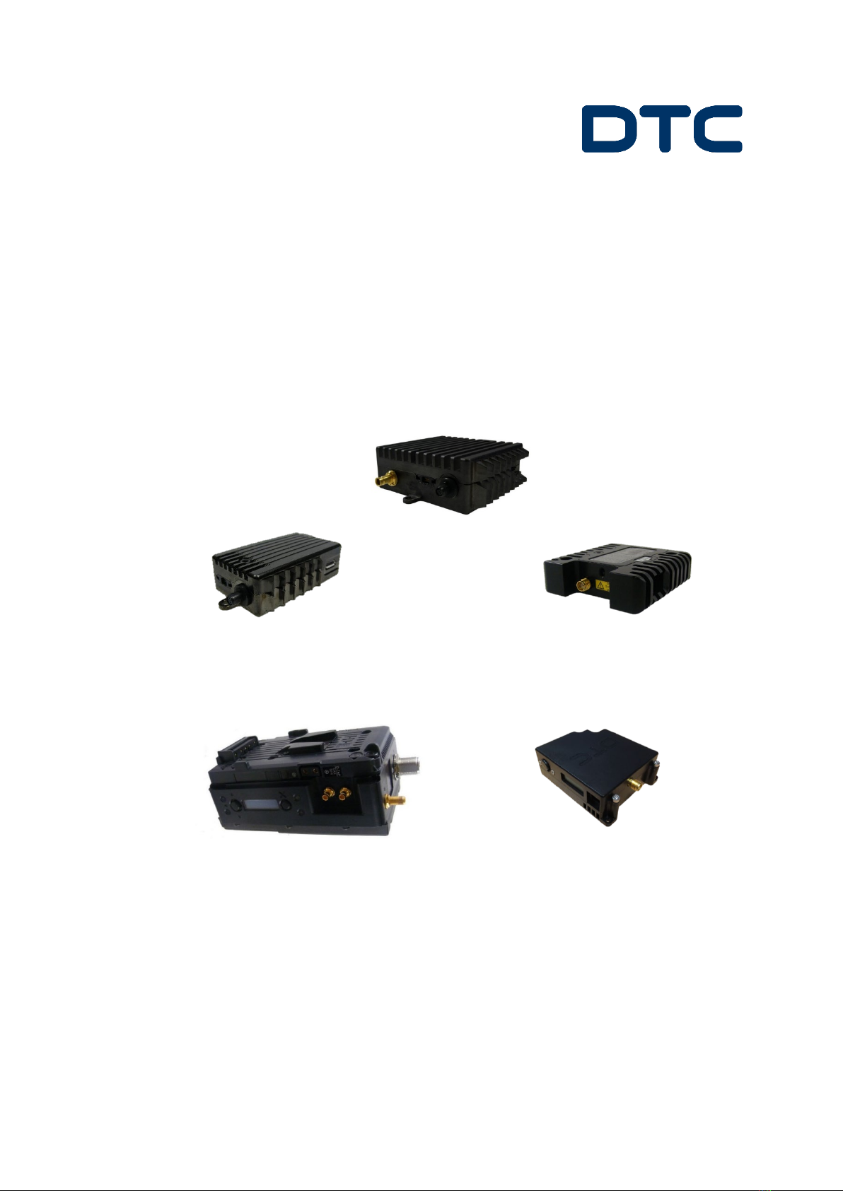
SOLO7 Transmitter Family User Guide
Copyright © 2013 Domo Tactical Communications (DTC) Limited. All rights reserved.
Commercial in Confidence
Contents
0. Preface......................................................................................................0-1
0.1 About this Document .................................................................................................................... 0-1
0.2 Intended Audience ........................................................................................................................ 0-1
0.3 Notice about this Publication........................................................................................................ 0-1
0.4 Text Conventions........................................................................................................................... 0-2
0.5 Symbols ........................................................................................................................................ 0-2
0.6 Copyright ...................................................................................................................................... 0-2
0.7 Related Documents....................................................................................................................... 0-3
0.8 Document History.......................................................................................................................... 0-3
1. Product Overview.......................................................................................1-1
1.1 Product Family .............................................................................................................................. 1-1
1.2 SOLO7 Nano Transmitter............................................................................................................... 1-2
1.3 SOLO7 HD Nano Transmitter ......................................................................................................... 1-3
1.4 SOLO7 Transmitter........................................................................................................................ 1-4
1.5 SOLO7 OB Transmitter .................................................................................................................. 1-5
1.6 SOLO7 Broadcast Nano Transmitter.............................................................................................. 1-6
1.7 Approval Notices ........................................................................................................................... 1-7
1.8 FCC Certification........................................................................................................................... 1-7
2. Product Package .......................................................................................2-8
2.1 Packaging Overview...................................................................................................................... 2-8
2.2 SOLO7 Nano Transmitter............................................................................................................... 2-8
2.3 SOLO7 HD Nano Transmitter ....................................................................................................... 2-11
2.4 SOLO7 Transmitter...................................................................................................................... 2-14
2.5 SOLO7 OB Transmitter ................................................................................................................ 2-17
2.6 SOLO7 Broadcast Nano Transmitter............................................................................................ 2-21
3. Controls, Connections and Indicators......................................................3-24
3.1 SOLO7 Nano Transmitter............................................................................................................. 3-24
3.2 SOLO7 HD Nano Transmitter ....................................................................................................... 3-26
3.3SOLO7 Transmitter...................................................................................................................... 3-28
3.4 SOLO7 OB Transmitter ................................................................................................................ 3-30
3.5 SOLO7 Broadcast Nano Transmitter............................................................................................ 3-32
4. Getting Started........................................................................................4-34
4.1 Starting and Stopping the Transmitter ....................................................................................... 4-34
4.1 Domo Device Controller ............................................................................................................... 4-34
4.2 Connecting your PC to the SOLO7 Transmitter............................................................................ 4-35
4.3 Domo Device Controller Primary Window..................................................................................... 4-37
4.4 Performing a Quick Setup ........................................................................................................... 4-38
5. Domo Device Controller Operation ...........................................................5-40