DTI WINCO PSS15B2W/A Setup guide

PACKAGED
STANDBY
SYSTEM
PSS15B2W/A
INSTALLATIONANDOPERATORSMANUAL
Engine Generator Set

Read and understand all instructions in the
manual before starting and operating the
generator set.
USING THIS MANUAL
Congratulations on your choice of a Winco generator set.
You have selected a high-quality, precision-engineered
generator set designed and tested to give you years of
satisfactory service.
To get the best performance from your new engine
generator set, it is important that you carefully read and
follow the operating instructions in this manual.
Should you experience a problem please follow the
“Things To Check” near the end of this manual. The
warranty listed in this manual describes what you can
expect from WINCO should you need service assis-
tance in the future.
TABLEOFCONTENTS
INTRODUCTION i
GUIDE TO PRODUCT SAFETY 1
BASIC INFORMATION 2
Description 2
Specification Table 2
PREPARING THE UNIT 3
Unpacking the Unit 3
ENGINE GENERATOR INSTALLATION 3
Installation 3
Fuel Installation 4
Vapor Fuel Pressure Tables 5
Fuel Conversions 5
Lubrication 6
Battery Installation 6
Connecting Battery Charger 6
TRANSFER SWITCH INSTALLATION 6
AC Electrical Connections 7
DC Electrical Connections 8
INITIAL START-UP 8
TROUBLESHOOTING INFORMATION 9
WIRING DIAGRAMS
Wiring Diagram 11
AC & DC Generator Schematic 12
ASCO 165 DC Wiring 13
Generator Layout 13
12 MONTH WARRANTY 15
PAGEi
PROPER USE AND INSTALLATION
You must be sure your new engine generator set is:
* Properly serviced before starting
* Operated in a well ventilated area
* Properly exhausted and gases safely dispersed
* Wired by a qualified electrician
* Operated only for its designed purposes
* Used only by operators who understand its operation
* Properly maintained
COPY YOUR MODEL AND SERIAL
NUMBER HERE
No other WINCO generator has the same serial number
as yours. It is important that you record the number
and other vital information here. If you should ever
need to contact us on this unit it will help us to respond
to your needs faster.
MODEL____________________________________
SERIAL NUMBER____________________________
PURCHASE DATE____________________________
DEALER___________________________________
DEALER PHONE # ___________________________

PAGE 1
4190-00 60706-169
SAFETY INFORMATION
This engine generator set has been designed and
manufactured to allow safe, reliable performance.
Poor maintenance, improper or careless use can
result in potential deadly hazards; from electrical
shock, exhaust gas asphyxiation, or fire. Please read
all safety instructions carefully before installation or
use. Keep these instructions handy for future
reference. Take special note and follow all warnings
on the unit labels and in the manuals.
ANSI SAFETY DEFINITIONS
************************************************************
DANGER:
DANGER indicates an imminently hazardous
situation which, if not avoided, will result in death or
serious injury. This signal word is to be limited to the
most extreme situations.
***********************************************************
************************************************************
WARNING:
WARNING indicates a potentially hazardous situation
which, if not avoided, could result in death or serious
injury.
***********************************************************
***********************************************************
CAUTION:
CAUTION indicates a potentially hazardous situation
which, if not avoided, may result in minor or moderate
injury. It may also be used to alert against unsafe
practices.
************************************************************
NOTE:
CAUTION is also used on the unit labels and in this
manual to indicate a situation that could result in
serious damage or destruction of the equipment and
possible personal injury.
1. ELECTRIC SHOCK - The output voltage present in this
equipment can cause a fatal electric shock. This
equipment must be operated by a responsible
person.
a. Do not allow anyone to operate the generator
without proper instruction.
b. Guard against electric shock.
c. Avoid contact with live terminals or receptacles.
d. Use extreme care if operating this unit in rain or
snow.
e. Use only three-prong grounded receptacles and
extension cords.
f. Be sure the unit is properly grounded to an
external ground rod driven into the earth.
2. FIRE HAZARD - Natural gas and L.P. present a hazard
of possible explosion and/or fire.
a. Do not refuel when the engine is running or hot.
Allow the engine to cool at least two minutes
before refueling.
b. Keep fuel containers out of reach of children.
c. Do not smoke or use open flame near the
generator set or fuel tank.
d. Keep a fire extinguisher nearby and know its
proper use. Fire extinguishers rated ABC by
NFPA are appropriate.
e. Store fuel only in an approved container, and only
in a well-ventilated area.
f. Follow local codes for closeness to combustible
material.
3. DEADLY EXHAUST GAS-Exhaustfumesfromany
gasoline engine contain carbon monoxide, an
invisible, odorless and deadly gas that must be mixed
with fresh air.
a. Operate only in well ventilated areas.
b. Never operate indoors.
c. Never operate the unit in such a way as to allow
exhaust gases to seep back into closed rooms
(i.e. through windows, walls or floors).
4. NOISE HAZARD - Excessive noise is not only tiring,
but continual exposure can lead to loss of hearing.
a. Use hearing protection equipment when working
around this equipment for long periods of time.
b. Keep your neighbors in mind when permanently
installing this equipment.
5. CLEANLINESS - Keep the generator and surrounding
area clean.
a. Remove all grease, ice, snow or materials that
create slippery conditions around the unit.
b. Remove any rags or other material that could
create potential fire hazards.
c. Carefully clean up any gas or oil spills before
starting the unit.
d. Never allow leaves or other flammable material
to build up around the engine intake or exhaust
area.
6. SERVICING EQUIPMENT -Allservice,includingthe
installation or replacement of service parts, should be
performed only by a qualified technician.
a. Use only factory approved repair parts.
b. Do not work on this equipment when fatigued.
c. Never remove the protective guards, cover, or
receptacle panels while the engine is running.
d. Use extreme caution when working on electrical
components. High output voltages from this
equipment can cause serious injury or death.
e. Always avoid hot mufflers, exhaust manifolds,
and engine parts. They all can cause severe
burns instantly.
f. Installing a generator set is not a “do-it-yourself”
project. Consult a qualified, licensed electrician
or contractor. The installation must comply
with all national, state, and local codes.

PAGE 260706-169 4190-00
TESTING POLICY:
Before any generator is shipped from the factory, it is
fully checked for performance. The generator is loaded
to its full capacity, and the voltage, current, and frequency
are carefully checked.
Rated output of generators is based on engineering
tests of typical units, and is subject to, and limited by, the
temperature, altitude, fuel, and other conditions specified
by the manufacturer of the applicable engines.
INTRODUCTION AND DESCRIPTION
The package standby system includes all items
necessary for a completely automatic standby power
system as standard equipment.
DESCRIPTION
This packaged standby system is designed to auto-
matically provide standby power to unattended loads
during electrical outages. Upon an interruption of normal
electrical service the packaged standby system electrical
control circuits will automatically start the engine. The
generator will produce electrical power and the Automatic
Transfer Switch (A.T.S.) will automatically transfer the
electrical loads to the engine-generator set. Upon
restoration of normal electrical service the emergency
transfer switch will sense return of the normal commer-
cial power. The Automatic Transfer Switch will retransfer
the load back to the normal commercial power source.
The engine control circuits will begin a cool-down cycle,
after which the fuel supply will be shut off and the engine
ignition system disabled.
These packaged standby systems consist of two
major components:
1) AUTOMATIC TRANSFER SWITCH
A wall mounted Automatic Transfer Switch
(A.T.S.) designed for inside installation. The NON-UL
A.T.S. consists of a line side contactor and a generator
side contactor. The contactors are both electrically and
mechanically interlocked. A seven day electronic exer-
ciser clock is installed in the A.T.S. as standard equip-
ment. The A.T.S. also contains the power failure sensing
circuitry necessary to send a start/stop signal to the
engine generator set.
Automatic Transfer Switch Sizes
(NON-UL)
UNIT LINE SIDE GENERATOR
CONTACTOR SIDE CONTACTOR
PSS15B2W/A 100AMPS 60 AMPS
UL Automatic Transfer Switch Sizes
UNIT LINE SIDE GENERATOR
CONTACTOR SIDE CONTACTOR
PSS15B2W/A 100 AMPS 100 AMPS
200 AMPS 200 AMPS
Both the 100 amps and the 200 amps UL Switches are
available in single and three phase. The UL A.T.S. have
a 14 day electronic exerciser circuit.
Additional optional A.T.S. sizes are available to meet
specific needs. Contact your local WINCO dealer, or the
WINCO Sales Department for a quote.
2) ENGINE/GENERATOR
The engine generator set consists of a Briggs & Strat-
ton, twin cylinder, four cycle air cooled engine. The
engine is factory equipped to run on L.P. or N.G. fuel.
The engine operates at 3600 rpm and frequency regula-
tion is maintained by the engine governor within 4 cycles
variation (62.5 Hz - 58.5 Hz) from no load to rated load.
The generator is a brushless, single bearing, direct drive,
rotating field design. Voltage regulation is provided by an
external voltage regulator mount on the generator,
variation is +/- .5% steady state.. The generator is
connected to the engine’s tapered (quill) crankshaft
extension. The engine generator is mounted in a NEMA
3R enclosure for outside installation. Connection boxes
are provided for all customer connections (both AC output
and DC control). A customer supplied 500 CCA (BCI
group 26) battery is required to complete the installation.
Engine operation is controlled by an Electronic Engine
Control Module (E.C.M.) mounted in the engine generator
enclosure. The E.C.M. is equipped standard with a 10
second start delay, 90 second cool down delay and cycle
cranking.
COLD WEATHER OPERATION
Extreme cold weather operation requires special
considerations. Higher CCA batteries are required for
cold weather starting, 650 CCA or larger are recom-
mended. In addition you should consider installing an
oil heater kit and a battery warmer for reliable starting
during cold weather.
** NOTICE **
This unit will automatically transfer if a power outage
occurs while running in an exercise mode.
SPECIFICATIONS
GENERATOR
MODEL WATTS* VOLTS AMPS* HZ PH RPM
PSS15B2W/A 15,000 120/240 60 60 1 3600
*Derate 16% for Natural Gas operation. Derate 3.5%
per 1000 feet elevation above sea level.

PAGE 3
4190-00 60706-169
FUEL CONSUMPTION
NG L.P. VAPOR
1000 BTU/CU FT 2520 BTU/CUFT
MODEL CF/HR BTU/HR #/HR* GAL/HR CF/HR BTU/HR*
PSS15B2W 260 260,000 2.7 2.96 108 272,160
*Based on full load operation
L.P. TANK SIZING
Required L.P. Tank size for L.P. Vapor withdrawal
operating at various outside temperatures given in
degrees Fahrenheit (Celsius)
TANK TEMPERATURE
MODEL 60 f(16 c) 32 f(0 c) 0 f(-18 c) -20 f(-29 c)
PSS15B2W 150 Gal. 250 Gal. 500 Gal. 1000 Gal.
ENGINE SPECIFICATIONS:
Refer to engine operating and maintenance instructions.
** NOTICE **
Regarding Engines - This manual covers the generator
portion of these units. See the separate engine instruc-
tion manual for engine-related problems, detailed engine
information and engine warranty.
** CAUTION **
Be sure to check the engine oil level frequently, as
specified in the engine manual.
The engine manufacturer has established an excellent
worldwide engine service organization; engine service is
available from a nearby authorized dealer or distributor;
check the yellow pages of the telephone directory under
“engines,” or ask the dealer from whom you purchased
the power plant.
The rated power of each engine-generator is limited by
the temperature, altitude and all other ambient conditions
specified by the engine manufacturer. Engine power will
decrease 3-1/2% for each 1000 ft. above sea level, and
will decrease an additional 1% for each 10 degrees
Fahrenheit above 60 degrees Fahrenheit.
UNPACKING INSTRUCTIONS
** NOTICE **
When unpacking the generator set, be sure to inspect it
carefully for freight loss or damage. If loss or damage is
noted at the time of delivery, require that the person
making the delivery make note of the loss or damage on
the freight bill, or affix his signature under the consignor’s
memo of the loss or damage. Contact the carrier for
claim procedures.
When loss or damage is noted after delivery, segregate
the damaged material, and contact the carrier for claim
procedures. Be sure to retain the packaging material for
carrier inspection.
“Concealed Damage” is understood to mean damage to
the contents of a package which is not evident at the time
of delivery by the carrier, but which is discovered later.
The carrier or carriers are responsible for merchandise
lost or damaged in transit. The title to goods rests with
the consignee when generators are shipped F.O.B.
factory, and only the consignee can legally file a claim.
Please note, most carriers have a time limit for filing
concealed damage claims.
**** CAUTION ****
These units are shipped without oil. Be sure to check oil
levels before operating. See engine manufacturer’s
instruction manual for recommended oil requirements
before initial starting.
UNPACKING:
1. Carefully remove the carton.
2. After inspecting the engine-generator and transfer
switch for external physical damage, check for the
following items packed inside the carton.
a. Owner’s manual, wiring diagram and parts list.
b. Engine manufacturer’s instruction manual.
3. Remove main frame hold down bolts, (4).
4. Unit can now be lifted from shipping pallet.
INSTALLATION
General Information
*************
***** WARNING ****
*************
Before proceeding with the installation, be sure the
operation selector switch is in the stop position.
These engine/generator sets are designed to be
mounted on a concrete pad outdoors only. The
transfer switch is mounted next to your electrical entrance
or distribution panel inside the building. Consult a
qualified, licensed electrician or contractor to install and
wire the transfer switch. The installation must comply with
all national, state and local codes.
Before beginning the installation process recheck the
rating of the generator set and its transfer switch rating.
Be certain they can handle the intended load and are
compatible with the entrance voltage, phase and current
ratings. Plans for installation should be prepared with
proper attention to mechanical and electrical engineering
detail to assure a satisfactory system installation. The
information in this manual is offered only as a guide to
finalizing your installation plans.

PAGE 460706-169 4190-00
ENGINE GENERATOR SET MOUNTING
The unit’s main frame should be bolted solid to a four to
six inch thick cement pad. The engine-generator is
mounted on a sub-frame which is isolated with special
shock mounts on the main frame. This allows the engine-
generator to vibrate without affecting the control panel on
the main frame.
Do not install any shock mounts between the base
frame and the concrete pad. Engine vibration will be
transmitted to the control panel causing erroneous start/
stop cycles and premature control failure.
The unit should be mounted to allow for ample working
room around it. A general rule to follow is three (3) feet
clearance on all sides. NFPA 37 requires at least 3 feet
clearance from any structures having combustible
adjacent walls and 5 feet from openings in walls. Particu-
lar attention should be paid to the direction of the hot air
discharge and exhaust discharge. Unit location should be
such that these discharges are not allowed to be drawn
back in through an open window or door.
FUEL INSTALLATION
The fuel supply should be as close as possible to the
engine. This will reduce the installation cost of fuel runs.
The information in this manual is offered to assist you in
providing the proper fuel for your engine. However, this
information is only provided to inform you of the engine’s
requirements and assist in making you aware of the
decisions you must make. In no case should the instruc-
tions or information provided be interpreted to conflict with
any local, state or national codes. If in doubt, always
consult your local fire marshal or gas supplier.
*************
***** WARNING ****
*************
FIRE HAZARD - All fuel runs should be installed by a
licensed fuel supplier.
To connect the fuel line, locate the 3/4 inch NPT fuel
inlet fitting on the side of the enclosure. This inlet is
shipped with a plastic cap plug installed to insure the fuel
system stays clean.
*************
***** WARNING ****
*************
FIRE HAZARD - DO NOT OVERTIGHTEN THE FUEL
LINE. THIS IS A TAPERED FITTING, OVERTIGHTENING
WILL CAUSE THE FITTING TO CRACK AND LEAK
FUEL.
For all vapor fuel systems the delivery pressure of the
fuel to the fuel solenoid on the unit must be four to six
ounces psi (per square inch) or 7 to 11 inches W.C.
(Water column). These fuel pressures are critical; failure
to provide the proper fuel pressure can cause many
problems ranging from a unit that will not start to causing
damage to the fuel system.
INSTALLING THE FUEL LINE
** NOTICE **
The engine generator sets are properly adjusted before
they leave the factory. A tag is attached to the unit that
specifies the fuel, natural gas (NG) or propane vapor (LP)
that the unit was set up and tested on.
Line Size
Unit location will determine the size of fuel line that is
required to supply the engine with a constant fuel pres-
sure and volume. Refer to the tables below for fuel line
size, fuel consumption and recommended tank size. For
distances of 50 feet and over, a two regulator fuel system
is recommended. This is accomplished by installing a
primary regulator at the tank which will reduce the tank
pressure down to 10 to 15 lbs. A secondary regulator is
installed to further reduce the fuel pressure to the required
four (4) to six (6) oz operating pressure. This secondary
regulator must be at least 10 feet from the engine genera-
tor set, any closer installation will require a larger line be
installed to provide a fuel reservoir. This is also true for
the single dual stage regulators, it should also be mini-
mum of 10 feet from the unit. If this is not done the
demand regulator on the unit and the pressure regulator
in the fuel line will interfere with each other.
When the two (2) stage regulator system is used, a fuel
line size of 1/2 to 5/8 inch is generally adequate for
distances up to 300 feet from the primary to the second-
ary regulator. (Consult your local fuel supplier for your
exact requirements.) The appropriate line size from the
table below is then installed from the secondary regulator
to the generator set.

PAGE 5
4190-00 60706-169
*************
***** WARNING ****
*************
PERSONAL DANGER - Do not use galvanized pipe in
fuel line runs. The galvanized coating can become
eroded and flake off, causing possible obstructions in the
regulator or fuel valve. The results could range from
inoperative engine start to hazardous fuel leaks.
NATURAL GAS or LP VAPOR
Size of pipe normally required for generators operating
on NATURAL GAS or LP VAPOR
up to 25 feet* 25 - 100 feet* over 100 feet*
use a two
PSS15B2W 3/4” pipe 1” pipe regulator system
*Allow an additional 3 feet for each standard elbow. Do not use
‘street ells’ (restrictive)*
**** CAUTION ****
Be careful when sealing gas joints. Excessive sealing
compound can be drawn into the solenoid, regulator or
carburetor causing an engine malfunction.
FUEL PRESSURE
L.P. & N.G. VAPOR FUEL
Correct fuel pressure cannot be stressed enough. The
most common cause for inoperative systems is an
inadequate or incorrect fuel pressure. Performance of the
engine is in direct relation to the correctness of the fuel
system. Shown below is a block diagram of a typical L.P.
or N.G. vapor fuel installation.
Notice the following tables give two (2) different units of
measuring fuel pressure. The first and most accurate is
the use of a simple water manometer. A manometer is
calibrated in inches of water column. The second is with a
pressure gauge calibrated in ounces per square inch.
Reference numbers 1 through 3 in the block diagrams
above are system parts supplied by customer.
Reference number 4 is the engine generator set.
Below is a table of the fuel pressure reading at each
reference in the system.
Fuel Pressure Table
Single Regulator (L.P. Vapor only)
1 3 4
UNIT OFF TANK PSI 7-11 in 7-11 in
4-6 oz 4-6 oz
STARTING TANK PSI 7-11 in 7-11 in
4-6 oz 4-6 oz
NO LOAD TANK PSI 7-11 in 7-11 in
4-6 oz 4-6 oz
FULL LOAD TANK PSI 7-11 in 7-11 in
4-6 oz 4-6 oz
Two (2) Regulator System (L.P. Vapor only)
1 2 3 4
UNIT OFF TANK PSI 10-15 lbs 7-11 in 7-11 in
4-6 oz 4-6 oz
STARTING TANK PSI 10-15 lbs 7-11 in 7-11 in
4-6 oz 4-6 oz
NO LOAD TANK PSI 10-15 lbs 7-11 in 7-11 in
4-6 oz 4-6 oz
FULL LOAD TANK PSI 10-15 lbs 7-11 in 7-11 in
4-6 oz 4-6 oz
Natural Gas
1 3 4
UNIT OFF LINE PSI 7-11 in 7-11 in
4-6 oz 4-6 oz
STARTING LINE PSI 7-11 in 7-11 in
4-6 oz 4-6 oz
NO LOAD LINE PSI 7-11 in 7-11 in
4-6 oz 4-6 oz
FULL LOAD LINE PSI 7-11 in 7-11 in
4-6 oz 4-6 oz
LP/NG FUEL CONVERSION
The PSS15B2W/A generator systems have been
tested on NATURAL GAS prior to shipment. If you are
going to use them on LP vapor, follow the procedures
outlined below to change the fuel type.
1. Connect your LP supply to the unit, making sure
that you have the correct fuel pressure.
2. Locate the vapor fuel adapter mounted between
the air filter and the carburetor body.

PAGE 660706-169 4190-00
3. Using an end wrench loosen the locking ring on the
adjustment screw.
4. Start the unit up and lean out the fuel to air mixture
by turning the adjustment screw in (clockwise). Keep
adjusting until the engine is running smooth. If you
lean it out too far the engine will start to slow down.
5. Check the unit to make sure it is still operating at
the proper speed (61.5 to 62 Hz). If it is correct
retighten the locking ring.
6. Test the unit under load to make sure it will work
properly.
If it should become necessary to change back to NG
from LP, just turn the adjustment out (counter clockwise)
until the engine is running smooth.
LUBRICATION
Before starting the engine, fill the crankcase with the
proper weight/grade of oil, as recommended by the
engine manufacturer’s maintenance instructions. The
necessity of using the correct oil, and keeping the
crankcase full cannot be over emphasized.
INSTALLING THE BATTERY
**** CAUTION ****
In the following battery installation procedure, check
toggle switch and make sure it is in the off position. This
should be your last step before initial start-up.
A customer supplied twelve-volt battery is required to
complete the installation. Installation of the highest CCA
rated battery, within the correct BCI group, will increase
cold weather starting performance. Gel batteries should
not be used with the battery tender installed in the
generator enclosure. MINIMUM
Model BCI Group CCA Rating
PSS15B2W 26 500*
* 650 CCA Recommended for cold weather starting.
*****CAUTION*****
EQUIPMENT DAMAGE - Always connect the positive
cable first and the negative cable last, when disconnect-
ing, it is negative cable first and positive last. Failure to
connect and disconnect in the proper sequence can
cause equipment damage.
Observe polarities: connect the positive (+) battery
terminal to the (+) cable from the control panel; the
negative (-) battery terminal is connected to the negative
cable (ground) from the engine generator assembly.
All connections must be clean and tight. Check the
electrolyte (fluid) in the battery periodically to be sure it is
above the plates. Never allow the battery to remain in a
discharged condition.
*****CAUTION*****
EQUIPMENT DAMAGE - NEVER JUMP STARTthese
units. Doing so will destroy the engine control module
rendering the unit non-operational. Remove and fully
recharge the battery before attempting to start.
CONNECTING THE BATTERY CHARGER
A two-stage battery tender is provided on all PSS series
generators. This battery tender charges at a rate of 750
mA until the battery is fully charged and then automati-
cally switches to a 13.2 VDC float charger. The charger
has an indicator light on it, red indicates it is charging, and
green indicates it is in the storage mode (float charge).
This charger is mounted on the engine generator set in
the same location as the other AC and DC connections.
This battery tender requires a circuit breaker protected
AC circuit from your distribution panel be run out to the
engine generator set. These AC wires can be run in the
same conduit as the other AC leads from the generator. It
is suggested that this circuit be fused for 15 amps.
A 120 volt receptacle is mounted in the generator
connection box. The receptacle is prewired with black,
white and green leads attached to it, this is where you
will connect your 120 volt fused power feed. This
receptacle can also be used when installing the oil heater
kit and the battery warmer.
** NOTICE **
The battery tender is not intended to recharge a battery
which has become completely discharged. It is designed
to produce enough current to recharge a slightly low
battery, maintaining it fully charged.
MOUNTING THE AUTOMATIC
TRANSFER SWITCH (A.T.S.)
*************
***** WARNING *****
*************
EQUIPMENT DAMAGE- Protect the switch from con-
struction grit and metal chips to prevent a malfunction or
shortened life of the switch. Contactors returned for
warranty consideration with foreign material inside of them
will not be warranted.

PAGE 7
4190-00 60706-169
The Automatic Transfer Switch connects the load (lights,
furnace, outlets, etc.) to the normal power line during
standby. When normal power fails, the A.T.S. starts the
engine generator set, disconnects the power line and then
connects the load to the standby generator set. When
normal power is restored, the automatic switch retransfers
the electrical load to the normal service and stops the
engine. The A.T.S. panel should be mounted as close to
the distribution panel as possible.
*************
***** WARNING *****
*************
All wiring must be done by a licensed electrician, and
must conform to the national electrical code and comply
with all state and local codes and regulations. Check with
your electrical inspectors before proceeding!
************
***** DANGER *****
*************
Be certain the operation selector switch on the front of the
A.T.S. Control is in the “stop” position and the main power
switch “off”. For your own protection, verify these impor-
tant safety precautions yourself with reliable instruments
before proceeding.
A.C. ELECTRICAL CONNECTIONS
*************
***** WARNING *****
*************
A FUSED DISCONNECT OR CIRCUIT BREAKER
MUST BE INSTALLED BETWEEN THE GENERATOR
AND THE A.T.S. PANEL TO PREVENT OVERLOADING
AND BURNING OUT THE GENERATOR. FAILURE TO
PROVIDE A FUSED DISCONNECT OR CIRCUIT
BREAKER, RATED AT GENERATOR RATING WILL
VOID YOUR WARRANTY IN CASE OF GENERATOR
FAILURE.
Generator Connections
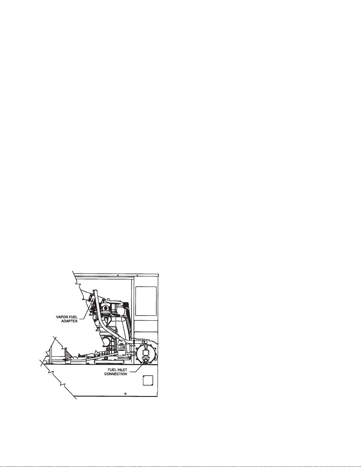
To gain access to the customer connections Remove
the end panel opposite the air dischage. All connections
including AC & DC connections to the ATS, 120 Volt
power connection for battery charger, fuel line connection
and battery installation are made behind this panel. After
removing the end panel you will need to remove the cover
over the connection box in the upper right hand corner.
Knockouts are provided on the outside of the enclosure
for your convenience. Three AC power leads are required
between the generator and the A.T.S. Two hot leads
connected generator leads G1 and G3 and a neutral lead
connected to generator leads N. A ground wire is also
required, which is connected to the ground lug mounting
bolt. These units are shipped with no neutral to
ground bond. You will need to run both the neutral and
ground leads in addition to the two power leads all the
way back to your distribution panel. Your distribution
panel should contain your only neutral to ground bond.
All power leads from the generator to the A.T.S. must
be sized to handle rated generator output amperage at a
minimum, the type of wire you use will determine the
gauge required. Consult your local wire supplier for proper
gauge and type for your area.
In addition to the power leads you will also need to run a
three wire 120 volt, 15 amp circuit from your distribution
panel to the generator. This circuit will be used to power
the battery charger and the optional block heater and
battery heater
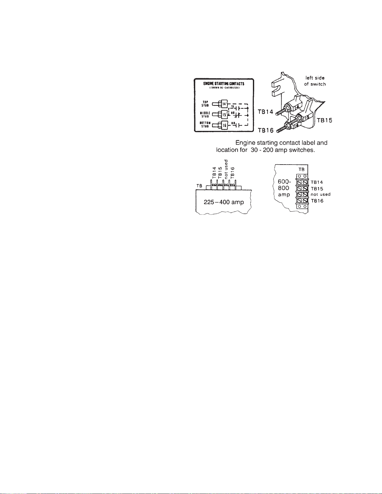
The last two wires you will need are the DC control
leads for the start circuit in the A.T.S. These last two
connections wil be discussed later in more detail.
A.T.S .Connections - for standard Non-UL WINCO ATS
The standby generator terminals in the A.T.S are
marked “GENERATOR - G1, G-N, G3”. The “hot” leads
G1 and G3 from the generator are wired to the generator
side contactor, terminals G1 and G3.
The line terminals in the A.T.S. are marked “LINE - L1,
L-N, L3”. The “hot” line leads L1 and L3 are wired to the
line side contactor, terminals L1 and L3.
The load terminals in the A.T.S. are marked “LOAD - T1,
T-N, T3”. The “hot” leads T1 and T3 are wired to the
bottom side of both the line side and the generator side
contactor.
If you are using a separate ground lead it is routed to
the ground lug in the A.T.S.
ASCO UL ATS (165 & 300 Series)
See the ASCO operator manual shipped with the
transfer switch for proper wiring instructions.
INSTALLATION NOTES
The load current carrying wires (L) and (T) must be
sized to handle the maximum load current without
excessive voltage drop. By code, the wire must be heavy
enough to handle the full current rating of the main line
circuit-breaker (or fuse) in the entrance (or sub-panel)
protecting the contactor switch.
All wires should be installed in rigid or flexible conduit.
(Knockouts are provided in the control box)
Because of the many different types of service, feeder,
and distribution equipment, no specific wiring instructions
can be provided. It is, however, recommended that only
copper wire be used. In all cases it is essential that while
the load is connected to the generator, there can be
absolutely no feedback from the generator to the power
line or the power line to the generator. When properly
installed, the normal A.T.S. control and safety systems will
eliminate all paths for feedback. Check with your local
electrical inspector on applicable local, state and federal
codes.

PAGE 860706-169 4190-00
*************
***** WARNING *****
*************
A service disconnect must be installed in front of the
A.T.S. panel as the A.T.S is not service entrance rated.
This will allow you to test the generator under load.
Should you ever have to work on the switch, you will be
able to disconnect the power and work on the switch cold
without having the power company pull your meter.
To wire the automatic transfer switch into the existing
wiring, first determine which circuits will be on the
emergency load circuit. If the entire load is to be trans-
ferred, the transfer switch can be wired in directly after the
watt-hour meter and the service entrance, providing the
service entrance ampere rating is within the transfer
switch’s rated capability.
If only specific circuits are to be powered under emer-
gency power failure conditions, an additional distribution
panel designated “emergency distribution panel” must be
installed.
All selected emergency circuits are removed from main
distribution panels and reinstalled in the emergency
distribution panel. Suggested circuits: freezer, refrigera-
tor, furnace, emergency lights, sump pump, emergency
outlet circuits, etc. Total running load must not exceed
generator rating.
D.C. ELECTRICAL INTERCONNECTION
*******CAUTION******
Never run the AC and DC wiring in the same conduit.
WINCO NON-UL ATS
Two control wires are required to be installed between
the A.T.S. panel and the generator control terminal box.
Depending on the distance 14 to 16 gauge stranded wire
should be used. These wires will be labeled “Bat -”, and
“Start”.
The control wires will be connected as follows in the
generator control terminal box:
ATS Panel Generator Control Panel
Start 1 to Wire # S1, (Bat Neg)
Start 23 to Wire # S23 (Start)
ASCO 165 UL SWITCH
Your DC connection points in the ASCO 165 UL ATS
are on the terminal block in the upper right hand corner of
the ATS panel. The terminal block is numbered 1 through
9. You will be using terminals 4 and 5, wire Start 23 will
connect to terminal #5 and wire Start 1 will connect to
terminal #4. See page 13 for a connection diagram.
ASCO 300 UL SWITCH
Your DC connection points in the ASCO UL ATS are
terminals “14” and “15” .Depending on the size of the
switch they are located in differnt locations. See below
INITIAL START UP
*************
***** WARNING *****
*************
DO NOT jump start these engine generator sets. Starting
these units on a low battery or jump starting them will
cause damage to the engine control module.
Use the following check list to verify correct installa-
tion before starting the engine:
FEngine oil.* Check level & fill as required with
proper grade/qty.
FUnit mounting base properly bolted down.
FClearance for service and maintenance on all
sides.
FProper fuel line material, and size.
FAll fuel line connections tight.
FFuel line protected and a moisture trap installed
(may be required for N.G.).
FLP/NG pressure O.K. 4-6 Oz. (7-11" WC).
FBattery connections clean and tight.
FBattery fully charged.
FAll A.C. and D.C. wiring installed and properly
protected.
* Refer to engine owners manual for proper
levels and type.
After completing the above checklist, the engine-
generator set is ready for the initial start-up test.

PAGE 9
4190-00 60706-169
PROCEDURE
Engine Generator Set only
Move the selector switch on the engine generator to the
“RUN” position. The engine-generator will crank and start
automatically. If the engine fails to start, return selector
switch to the “stop” position and correct the trouble before
proceeding.
With the engine running smoothly, check the no load
voltage and frequency at terminals G1 and G3 on the
generator terminal block in the A.T.S. The voltage
between G1 and G3 should be between 240 +/- 5 volts.
The frequency should be between 61.5 to 62 hertz (Hz).
The voltage should also be checked between the hot
terminals (G1 and G3) and the G-N to be certain of a
balanced voltage output and a solid neutral connection.
The voltage between G1 and G-N should be about one
half of the line to line (G1 to G3) voltage or approximately
120 +/- 3 volts AC. The same approximate voltage should
be found between terminals G3 and G-N.
** Notice **
If for any reason during the check out procedure the
voltage and frequency are not correct, turn the selector
switch to the “STOP” position and correct the trouble
before proceeding.
After verifying the voltage and frequency are correct,
turn the selector switch to the “STOP” position. The unit
should shut off with no time delay. You are now ready to
test the automatic start function.
Move the toggle switch to the “AUTO” position and
follow the instructions in the manual you received with the
transfer switch for initial start up and testing. Each of the
transfer switches has a different procedure. Remember
the unit will go into a short time delay before starting after
it receives the start signal from the transfer switch.
If it fails to start at this time, check your DC interconnec-
tion wiring. As long as line power is still applied to the
transfer switch during this test period the A.T.S. will not
transfer the load to the generator. Remember that there is
a 90 second cooldown delay built into the engine control,
so the unit will run during this period after the A.T.S. tells it
to stop.
Next you need to test the complete system. To accom-
plish this you will have to fail the incoming line power to
the A.T.S. panel. All the loads connected to the A.T.S.
should now be dead. The engine generator set will go
into a 3 to 10 second start delay. At the end of the start
delay the unit will start up. As soon as the engine
generator set reaches operating speed the transfer switch
will transfer the load to the engine generator on the Winco
Non-UL switches on the UL switches there is a short
delay before it transfers.
Restoring the line power will allow the transfer switch to
return the load to line power.
The restoration of line power also sends a stop signal to
the engine generator set. This stop signal will activate a
cool down timer circuit. The engine generator will shut
down 90 seconds later. The UL switches will have an
additional cool down delay built into the switch of as long
as 5 minutes.
This completes your installation and unit testing.
ALWAYS leave the system in automatic mode unless
servicing the unit. For automatic operation, keep both the
generator set and transfer selector switches in the
“AUTOMATIC” position.
TROUBLESHOOTING TABLES
*************
***** WARNING *****
*************
NEVER JUMP START THESE UNITS.
JUMP STARTING THESE UNITS WITH
LOW OR BAD BATTERIES WILL CAUSE
PERMANENT DAMAGE TO THE ENGINE
CONTROL MODULE.
UNIT WILL NOT CRANK WHEN THE
POWER FAILS.
1. Generator control switch not in “AUTOMATIC”
position.
2. Low or dead battery, must hold 12 volts during
cranking.
3. Incorrect wiring between transfer switch and
generator.
4. Circuit breaker tripped on engine control.
5. Loose or dirty battery terminals.
6. Defective “RUN/TEST/AUTO” switch.
7. Defective starter.
8. Defective start solenoid.
9. Defective start/stop control in the transfer switch.
10. Engine Control in fault from previous run cycle.
11. Blown 3/4 amp fuse on generator control panel.
ENGINE WILL NOT CRANK WITH GENERATOR
SELECTOR SWITCH IN THE START POSITION.
1. Low or dead battery, must hold 12 volts during
cranking.
2. DC circuit breaker on control module tripped.
3. Blown 3/4 amp fuse on generator control panel.
4. Loose or dirty battery terminals.
5. Defective “RUN/OFF/AUTO” switch.
6. Defective starter.
7. Defective start solenoid.
8. Locked up engine generator set.
ENGINE CRANKS BUT WILL NOT START.
1. Improper fuel pressure being delivered to unit.
2. Fuel supply shut off.
3. Fuel tank empty.

PAGE 1060706-169 4190-00
4. Defective spark plug.
5. Defective engine ignition module.
6. Dirty air cleaner filter.
7. Defective fuel solenoid valve.
8. Low voltage from battery to fuel solenoid, must
hold 12 volts during cranking.
9. Oil in the bottom of air cleaner from crankcase
breather.
ENGINE STARTS AND THEN STOPS.
1. Engine is low on oil.
2. Faulty oil pressure switch on engine.
3. No Generator output. (OCR)
ENGINE WILL NOT COME UP TO SPEED
AFTER IT STARTS.
1. Insufficient fuel volume getting to the unit.
a. Fuel line too small.
b. Low fuel pressure.
2. AC short circuit.
3. Wiring to the A.T.S. panel crossed or shorted.
4. Unit is overloaded, check load amperage.
ATS PANEL WILL NOT TRANSFER TO
EMERGENCY SUPPLY (GENERATOR).
1. No AC generator output from generator.
2. Wiring error between generator set and transfer
switch.
3. See ASCO manual for ATS troubleshooting.
ATS PANEL WILL NOT PULL IN ON
NORMAL POWER.
1. Proper normal line power not available at line
terminals in ATS panel.
2. See ASCO manual for ATS troubleshooting.
NO AC OUTPUT FROM GENERATOR.
1. Diodes on rotor blown.
2. Defective Voltage Regulator.
3. Defective rotor.
4. Defective stator.
5. AC short in the output leads.
6. Unit has lost its residual voltage.
7. Rotor loose on engine crankshaft.
8. Low engine speed, must be 3600 RPM.
9. AC short on output leads.
PREVENTIVE MAINTENANCE
Reasonable care in preventive maintenance will insure
high reliability and a long life for the engine generator set
and the Automatic Transfer Switch.
*************
***** WARNING ****
*************
When performing any type of maintenance on this
equipment make sure the selector switch on the engine
generator is in the off position. If you are working in the
Automatic Transfer Switch, confirm with a reliable meter
that all power has been disconnected.
AUTOMATIC TRANSFER SWITCH
Clean and inspect the switch once a year. De-energize
all power sources, both line and engine generator set,
then brush and vacuum away any excessive dust and
dirty accumulation. With the contactor de-energized you
can remove the contactor covers and check the contacts.
Make sure the contacts are clean and not burned or
pitted.
ENGINEGENERATORSET
Service the engine in accordance with the engine
manufacturers manual provided with your new equipment.
Routinely remove debris and dirt from around and inside
generator enclosure. Insure that the air intakes are free
from leaves and other debris at all times.
Clean and inspect battery terminals at least twice a year.
Check the battery water level at least twice a year also.
Other than keeping the generator clean and free of
debris there is no other routine or preventive mainte-
nance required, as long as the generator is run once or
twice every other week to keep it dry and in good working
order.

PAGE 11
4190-00 60706-169
AC AND DC GENERATOR WIRING DIAGRAM

PAGE 1260706-169 4190-00
AC AND DC GENERATOR SCHEMATIC

PAGE 13
4190-00 60706-169
GENERATOR LAYOUT

WINCO, Incorporated warrants to the original purchaser for 12 months that goods manufactured
or supplied by it will be free from defects in workmanship and material, provided such goods are
installed, operated and maintained in accordance with Winco written instructions.
WINCO’s sole liability, and Purchaser’s sole remedy for a failure under this warranty, shall be
limited to the repair of the product. At WINCO’s option, material found to be defective in material or
workmanship under normal use and service will be repaired or replaced. For warranty service,
return the product within 12 months from the date of purchase, transportation charges prepaid, to
your nearest WINCO Authorized Service Center or to WINCO, Inc. at Le Center Minnesota.
THERE IS NO OTHER EXPRESS WARRANTY.
To the extent permitted by law, any and all warranties, including those of merchantability and fitness
for a particular purpose, are limited to 12 months from date of purchase. In no event is WINCO
liable for incidental or consequential damages.
Note: Some states do not allow limitation on the duration of implied warranty and some states do
not allow the exclusion or limitation of incidental or consequential damages, so the above limita-
tions may not apply in every instance. This warranty gives you specific legal rights which may vary
from state to state.
WINCO reserves the right to change or improve its products without incurring any obligations to
make such changes or improvement on products purchased previously.
EXCLUSIONS:
WINCO does not warrant Engines, Batteries, or Other Component Parts that are warranted by
their respective manufacturers.
WINCO does not warrant modifications or alterations which were not made by WINCO, Inc.
WINCO does not warrant products which have been subjected to misuse and/or negligence or
have been involved in an accident.
225 SOUTH CORDOVA AVE
LE CENTER MN 56057
Phone: 507-357-6831
P/N 60706-169
4190-00
Table of contents
Other DTI Portable Generator manuals
Popular Portable Generator manuals by other brands

Champion
Champion 100423 Operator's manual

Thunder Scientific
Thunder Scientific 2500 series Operation and maintenance manual

LawnMaster
LawnMaster LGBQH9200 Safety and operating manual

Mobiltech
Mobiltech ZEUS80 CD user manual

SIGLENT
SIGLENT SDG1000X Series Service manual

Powermate
Powermate PMA525302.01 owner's manual