DTM System DTM GO800 User manual

1
AUTOMATION SYSTEMS
GARAGE DOOR OPENER
Assembly instructions for the installer
Version 1 DTM GO800
DTM System spółka z ograniczoną odpowiedzialnością spółka komandytowa
ul. Brzeska 7, 85-145 Bydgoszcz
tel./fax. (52) 340-15-83, 340-15-84
www.dtm.pl, [email protected]

2
SECURITY OF IMPLEMENTATION OF THE AUTOMATION SYSTEM
Before starting the installation, carefully read the entire product installation and operation manual.
Non-observance and non-compliance with the notes in this manual may lead to an accident in which people
are injured or property damage occurs.
The gate drive ensures correct and safe operation only if the installation and use comply with the following
safety rules. DTM System is not responsible for accidents resulting from improper use or unprofessional
installation of devices.
The drive has an electronic obstacle detection mechanism. In order to ensure an adequate level of
safety, the adjustment of the force should be performed with particular care.
·Do not leave packaging materials within the reach of children, as they are potentially dangerous;
·This product has been designed and manufactured solely for the intended use described in this
documentation. Using it for any other purpose may adversely affect the technical condition and
operation of the device and is a potential source of danger;
·DTM System is not responsible for the consequences of improper use, not in accordance with the
intended use;
·The drive must be operated in a dry room;
·Do not install the device in an environment with an increased risk of explosion or aggressive air;
·If possible, install the drive at least 2.1 meters above the ground;
·If a rail extension is installed on a heavy gate with the drive, use a second ceiling suspension;
·The half-open gate must remain in this position. If the gate moves up or down, it must be
mechanically adjusted;
·It is allowed to install the drive moved away from the symmetry axis of the gate if it does not cause
deformation of the gate itself and allows the gate to move properly in the guides;
·Automatic swing gates should comply with the standards as well as with any applicable local
regulations, they must comply with the requirements of EN 12604;
·DTM System is not responsible for the consequences of design defects of the driven elements or for
their deformation that may occur during use;
·The walls and ceilings to which the drive is to be mounted must be strong and stable;
·The installation must conform to the requirements of EN 12453. The safety level of the C + D
automated system is required;
·Before starting any work on the system, disconnect all power sources;
·The electrical installation to which the automation is connected must comply with the applicable
standards and be properly made;
·The installer should provide the device with a residual current device ensuring that the devices are
cut off from the main power supply. The standards require a separation of the contacts of at least
3mm in each pole (EN 60335-1). It is recommended to use a 6A thermal fuse with a circuit breaker for
all circuits;
·Take care to protect the power circuit with a differential switch with a threshold of 30mA;
·Safety mechanisms (EN12978 standard) provide protection against the risks associated with the
movement of moving mechanical parts, such as crushing, snagging or detachment;
·DTM System is not responsible for the safety and efficient operation of the automation system in
the event of using components that are not products offered by DTM System;
·Only genuine parts should be used for servicing;
·Do not modify the automation components in any way;
·The end user should be informed about the method of handling, dealing with failures and about the
dangers of using the automation system;
·During the operation of the automation system, both children and adults must keep a safe distance
from the operating automation;
·The automation system can only be operated by properly trained adults
·Control devices should be out of the reach of children in order to protect the automation system
against accidental activation;
·Movement through the gate is allowed only when it is fully open;
·Service is only permitted by qualified personnel;

3
·During the assembly or repair work of the automatic gate, be careful not to wear jewelry, watches
or loose clothing;
·Remove any locks installed on the gate to avoid damaging it, and remove all ropes and loops used to
open the gate manually;
·After installation, it is necessary to check that the mechanism is properly set and that the drive,
safety system and emergency unlocking work properly;
·The gate drive cannot be started and continue to operate when there is a wicket in the gate and it is
not properly closed;
·Crush or injury protection systems (e.g. photocell systems) must function properly after the drive is
installed and connected to the mains;
·The radio remote control may only be used when a safe force value is set;
·The radio remote control may only be used if it is possible to observe the gate movement and there
are no people or objects in the movement area;
More information in European Union documents:
EN 12453:20017-10 Gates. Safety of use of power operated doors.
Requirements and test methods.
EN 12604:2017-11 Gates . Mechanical aspects. Requirements and test methods.
EN 12978+A1:2012 Doors and gates. Safety devices for motorized doors and gates.
Requirements and test methods.
EN 12100:2012 Machine safety. General principles of design.
Risk assessment and risk reduction.
EN 60335-1:2012 Safety of electrical appliances for household and similar use.
General requirements.
Health and safety rules

4
SAFETY IN THE USE OF THE AUTOMATION SYSTEM
Non-observance and non-compliance with the notes in this manual may lead to an accident in
which people are injured or property damage occurs. Please read the following warnings carefully. The gate
drive ensures correct and safe operation only if the installation and use comply with the following safety
rules. DTM System is not responsible for accidents resulting from improper use or unprofessional
installation of devices.
·During the operation of the automation system, both children and adults must keep a safe distance
from the operating automation.
·The automation system can only be operated by properly trained adults.
·Control devices should be kept out of the reach of children in order to protect the automation
system against accidental activation.
·Movement between the gate leaves is allowed only when it is fully open.
·Do not obstruct the gate movement.
·Remove any obstacles that impede gate movement.
·Signal lamps and signboards must be operational and clearly visible.
·Manual operation of the door is possible only when the power supply is disconnected and the door is
unlocked.
·In the event of a failure, disconnect the power, release the gate to allow access, and then call the
service center for necessary repairs.
·Do not attempt to repair or maintain the system yourself. The system may only be serviced by
qualified personnel.
·At least every 6 months, the operation of the automation system, protection devices and protective
circuits should be checked by qualified personnel.
·Make sure that the persons who install, maintain or operate the gate automation follow these
instructions. Keep these instructions in a place where you can refer to them quickly when needed.
WARRANTY
DTM System delivers the equipment in working order and ready for use and provides a 24-month
warranty from the date of purchase by the end customer. The warranty period is determined on the basis of
warranty seals or the manufacturer's production batch markings placed on each product. DTM System
undertakes to repair the device free of charge if during the warranty period there are defects due to the
manufacturer's fault. The defective device must be delivered to the place of purchase at your own expense, with
a short, unambiguous description of the damage. The cost of disassembly and assembly of the device is borne by
the user. The warranty does not cover any damage resulting from improper use, unauthorized adjustments,
alterations and repairs as well as damage resulting from lightning, overvoltage or short circuit of the power
supply network. The detailed terms and conditions of granting a guarantee are regulated by relevant legal acts.

5
1. Introduction
1.1General information
The DTM System electromechanical drive is designed to automate garage doors. The assembled and
launched system can be conveniently operated by radio transmitters (remote controls).
1.2. Technical data
•power supply 230 VAC / 50Hz
•current consumption / at rest 1A / 0.04 A
•protection class IP-20
•maximum gate movement speed: 125 mm / s
•maximum drawbar pull: 800N
•work intensity 15% (9 cycles / h)
•temperature range -20 ° C to + 50 ° C
•built-in lighting / lighting time permanent LED / 4min.
•length of the running rail with drive and handle: 3440 mm, folded from elements, with toothed belt
•maximum stroke of the trolley: 2650mm
•maximum door width: 5000 mm
•maximum door area of 12.6 m2
•automation control wall button / radio remote controls
•input for safety devices yes, photo input
•accessories power output: yes, + 24VDC max. 100mA
•operating modes: open, close, step by step, close after time, airing
•photo input operating modes: stop, reverse when closing or closing and opening
•retraction of the trolley after closing: yes, 1-5mm
1.3 Mechanical components
Before starting work, check if all the elements shown in fig. 1 are present, and then read the entire
manual.
2. MECHANICAL ASSEMBLY
2.1. Verification of the type and structure of the gate
In order to properly complete and install the automation system, verify the type of your gate and check
the structure of the existing or installed gate against the requirements set out below:
Technical data / Introduction
Fig. 1. Necessary mechanical elements.
4xM6
4xM6
6
2x
2x
6
1
3
10
7
8
11
92a
2b
2c
4
5
1
23
4
Part definition:
1 drive head with lighting;
2a a C-shaped rail together with a toothed drive belt;
2b "C" shaped rail with holes;
2c "C" shaped rail;
3 slip-on connectors, 2 pieces;
4 carriage and emergency release locking mechanism;
5 remote control transmitter
6 ceiling hanger;
7 pin and securing pin, bolt and tension spring;
8 front piece;
9 a tension element;
10 cart-gate pusher;
11 gate hardware;

6
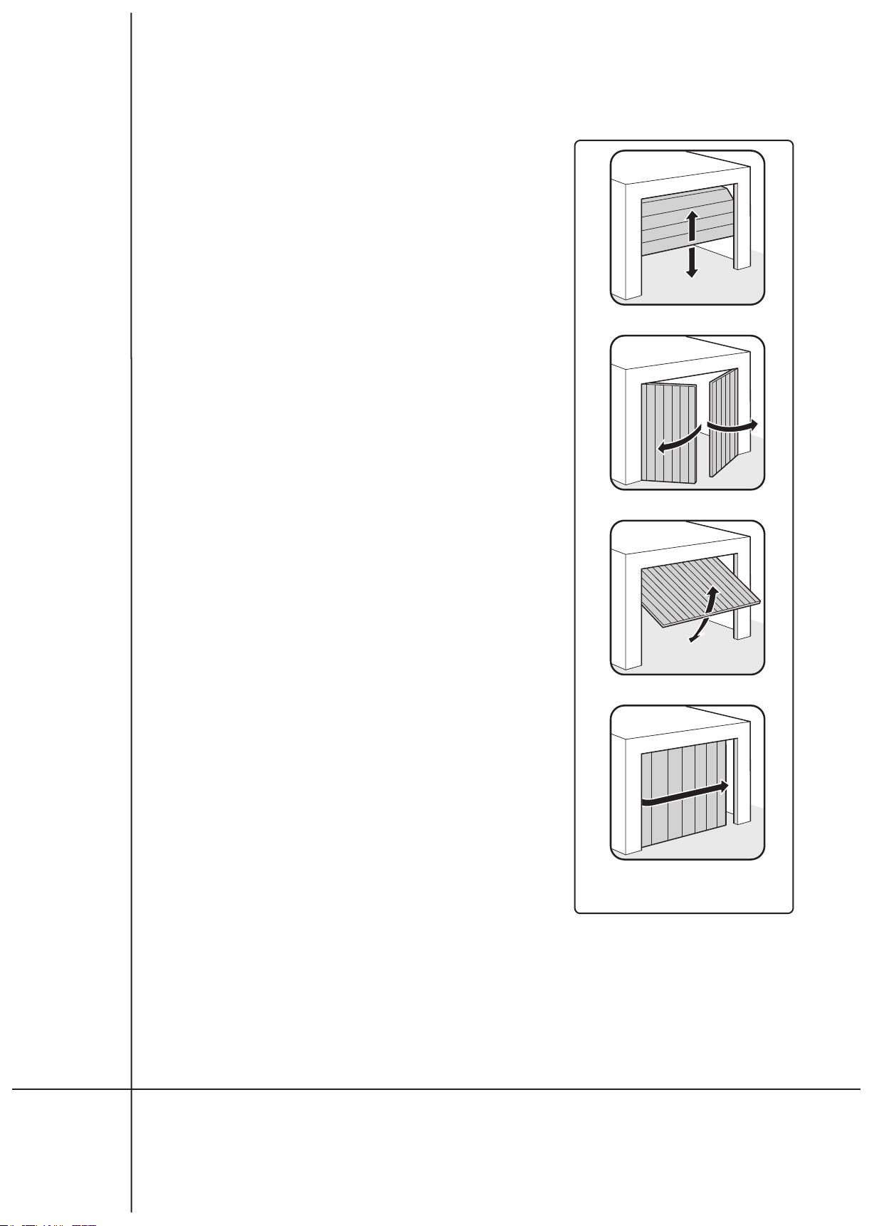
•The basic set allows you to automate sectional doors with an ordinary running rail - it is recommended to
use a "boomerang" type handle, with a double running rail - without a "boomerang", up-and-over gates -
without a "boomerang", and after adding an additional elements for side and swing gates (figure 2);
•The structural elements of the gate must meet the requirements of EN 12604 and EN 12605;
•The dimensions of the gate must not exceed the dimensions given
in the drive parameters;
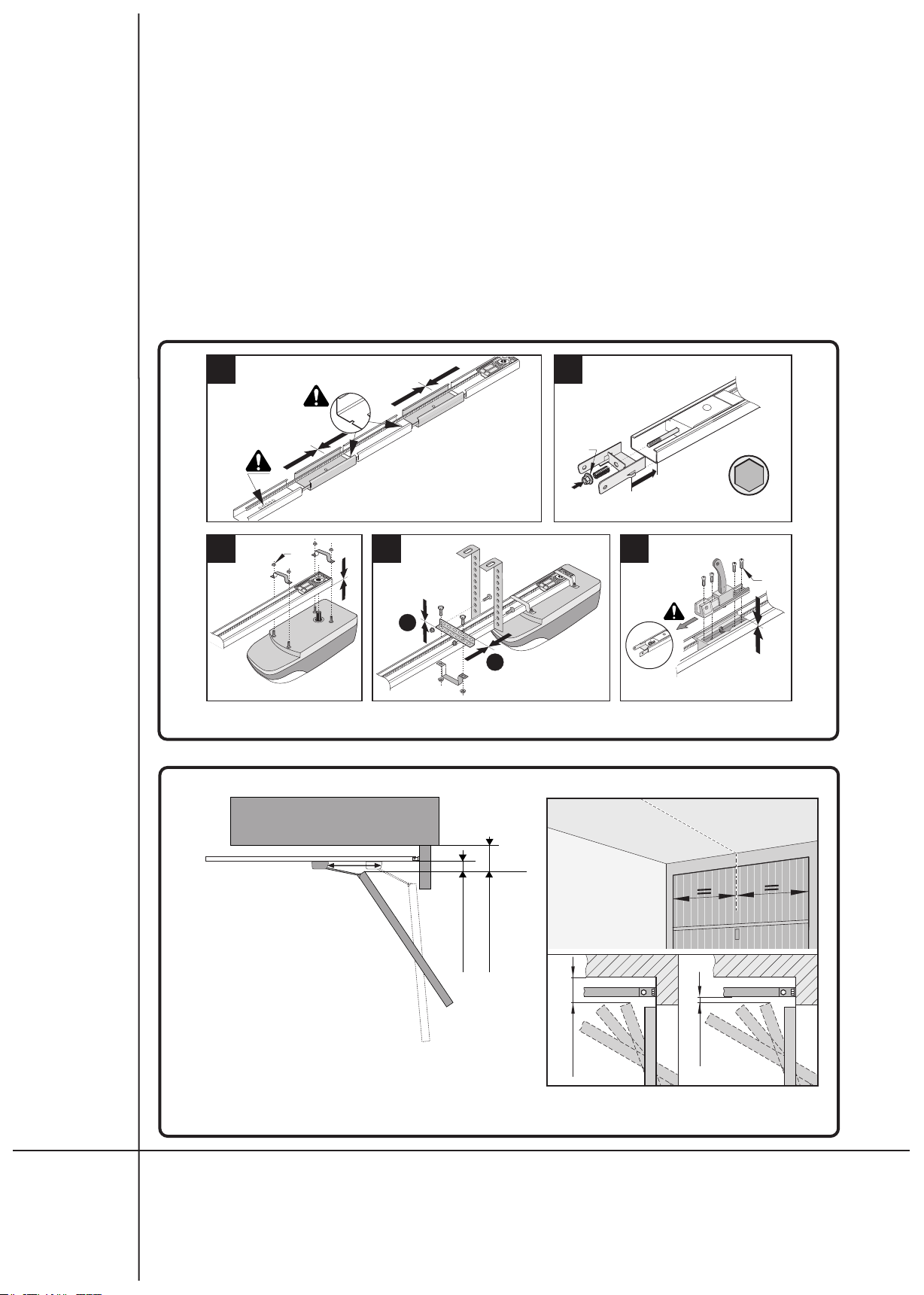
•Check the possibility of mounting the drive, taking into account
the installation dimensions;
•The drive mechanism requires sufficient space between the ceiling
and the door for mounting the running rail. It should also be
checked whether the part of the drive protruding beyond the load-
bearing structure of the gate has sufficient space.
•assembly of the automated system;
•The gate must move smoothly and freely throughout the entire
range of motion without any resistance;
•After opening the gate to half its height, the gate must remain in
this position, free movement up or down should be corrected by
appropriate adjustment of the gate;
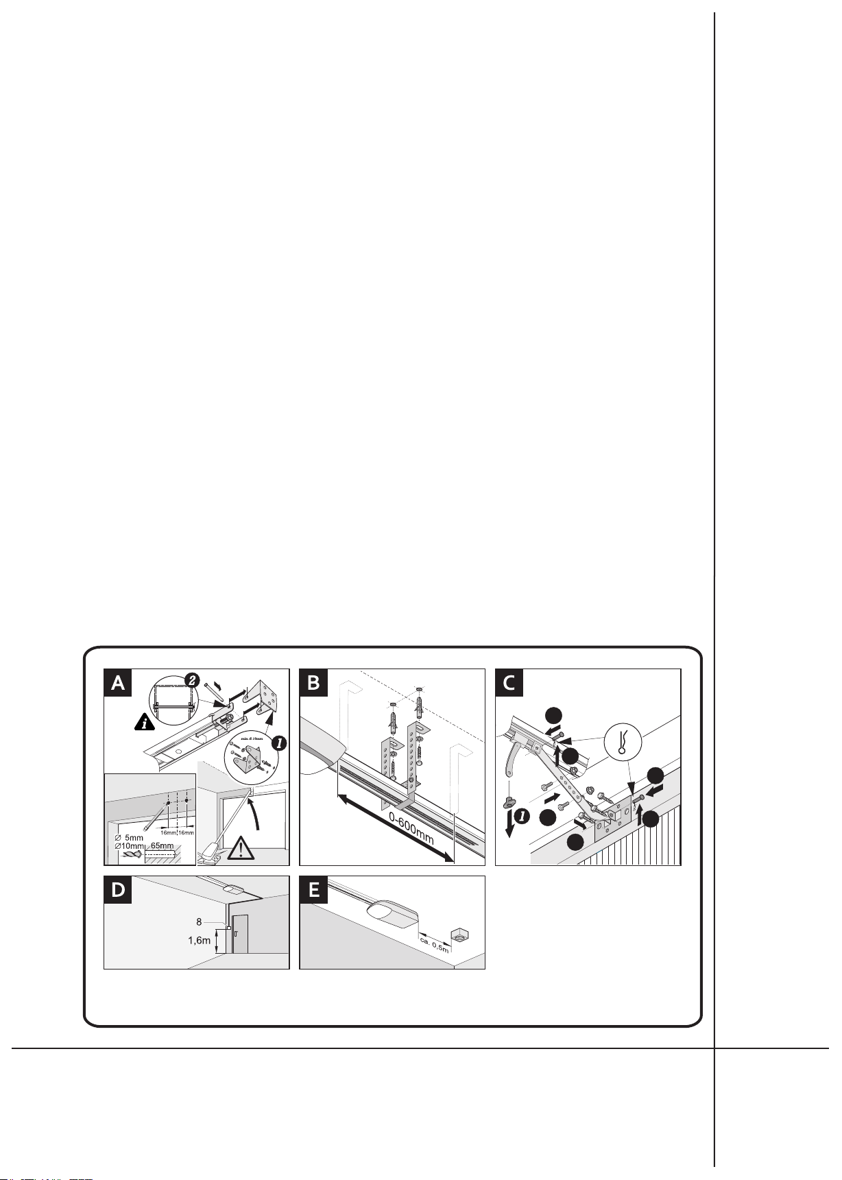
•Check that the electrical installation allows the connection of the
drive. If this is not the case, qualified personnel must provide a
230VAC power socket at a distance of about 0.5m from the drive
head.
Notes on the gate and its surroundings:
•The area of the gate is an approximate parameter. However, the
maximum permissible door size should not be exceeded. The actual
force transmitted by the drive is influenced by: gate type, gate
weight, air movement around the gate;
•Low temperatures and high humidity may make it difficult or
impossible to start the automation;
•The drives are not designed for continuous operation, the maximum
operating frequency specified in the drive parameters must be
maintained;
•The gate must operate smoothly and without impact, movement
must be smooth and unobstructed;
•The drive cannot be used to operate emergency exits or gates on an
escape route (see escape routes);
•If there is a pedestrian door on the powered door, a safety switch
must be installed to prevent the automatic system from operating
when the door is open;
•The condition of the door structure has a direct impact on the
reliability and safety of use of the entire system
•It is recommended to complete the assembly of the steel structure
before installing the drive;
•Determine what materials are needed to install the kit and provide
them before starting the installation. This applies to anchors, bolts,
brackets, cables, electrical fixtures, tools.
2.2. Preparation of the gate
The type of gate determines the position in which the drive will be installed. The gate hardware should
be attached to the main frame or to the gate panel through a suitable holder. When the bracket is not sufficiently
stable, it must be strengthened. When we have a wooden gate, the gate hardware should be screwed "through".
In such cases, it is advisable to use the board from the outside so that the fastening cannot loosen over time.
Delicate aluminum, wooden gates must be additionally reinforced to withstand the stresses caused by the drive.
Fig. 2. Types of garage doors.
sectional gate
swing gate
up-and-over gate
side gate

7
2.3. Stops and locks
Any cables or loops used for manual opening and closing of the gate and gate blocking
mechanisms should be removed, unless they are automatically activated by the drive!
2.4. Mechanical assembly
2.4.1. Initial assembly of the drive - preparation of the gearmotor for installation on the gate
Prepare the elements as shown in Fig. 1.
Assemble the rails in accordance with the drawing 4A, paying careful attention to their precise
sliding with the connecting fittings.
Slip the front element on the rail and put the screw through it so that it can be "grabbed" on the
other side with the help of a spring and a nut, fig. 4B. Using an appropriate socket wrench, screw in the
screw until the toothed belt is tight.
Referring to Figure 4C, mount the drive head to the rail, paying attention to the correct positioning
of the drive shaft in the toothed belt pulley spline.
After mounting the drive head, you can proceed to install the ceiling hanger as shown in Fig. 4D.
Other slings can be used if required, e.g. for a much higher mounting surface.
In a correctly assembled rail with a V-belt, find the lower part of the trolley and screw the trolley part
with the unlocking mechanism to it, Fig. 4E. Also attach the cable to help unlock the drive.
2.4.2. Installation of the drive and manual control of working conditions
Measure the center of the gate and mark it at the leaf and lintel above the gate.
Open the door slowly and determine the smallest distance between the most protruding movable part
of the door and the ceiling - THP. This dimension must be at least 35 mm. The spacing between THP and the lower
edge of the C-rail must be at least 5 mm and up to 65 mm (so that the trolley arm was at an angle of 30 °, figure 5.
Close the gate and, depending on the available space, install the drive to the lintel. Trace horizontally,
symmetrically, two holes at a distance of 16 mm from the gate axis each and 20-80 mm above the THP, as shown
in Fig. 5. Drill, depending on the type of substrate, with a 10 mm drill bit in concrete or 5 mm diameter in wood.
Fasten the front handle of the drive to the lintel prepared in this way, Fig. 6A [1] (using expansion
bolts, etc. - so that the fixing ensures a sufficient level of safety. These activities should be entrusted to a
qualified person with the necessary experience). Then, using the pin and cotter pin, connect the front of the
rail to the handle, Fig.6A [2].
Then, using e.g. a ladder (suitably solid and stable), initially level the drive.
If necessary, release the trolley by pulling down once on the emergency release mechanism, Fig. 6C [1].
Move the trolley back and open the gate.
Position the ceiling hanger approx. 300 mm from the controller housing (depending on the door
structure and the ceiling, the hanger can be mounted in the range from 0 to 600 mm relative to the controller
housing, Fig. 6B).
Rys. 3. Materiały i narzędzia niezbędne przy montażu zestawu.
Mechanical assembly
5mm 10mm10mm
13mm
14mm
14mm
2x
2x

8
Position the hanger angles vertically and the drive rail in a line parallel to the gate axis (if there was no need to
move the front fixing relative to the gate axis, the center of the gate will be the center of the drive rail).
Mark, drill and attach the hanger to the ceiling Fig. 6B and, if necessary, shorten the ends of the angles
that protrude downwards.
Move the trolley with the attached bar and gate hardware, Fig. 6C [2..6] towards the closed gate and
centrally (if the entire drive has not been moved) fix the fitting to the gate leaf using self-selected fixing elements,
Fig. 6C [ 7].
Couple the trolley with the door by pulling the cable „backward". The lever to which the cable is attached
must change its position from vertical to horizontal.
Fig. 4. Initial assembly of the drive.
Fig. 5. Definition of dimensions and recommended values.
A
M10
14mm
B
1
2
D
4xM6
C E
4xM6
•THP - the smallest distance between the
top edge of the door and the ceiling
during the opening / closing movement.
This value is minimum 35mm;
•the distance between the THP and the
running rail should be between 5 and
65mm;
•the lintel height should be at least 35mm
from the THP.
THP min. 35mm
5 - 65mm
min. 35mm
5-65mm
THP

9
3. Electrical installation
IMPORTANT REMINDER
Electrical installations and automation of the drive must be performed by experienced and qualified personnel in
accordance with applicable legal regulations. There are dangerous voltages of 230V 50Hz in the devices, all
connections must be made with the voltage turned off. The installer's task is to install the system in a safe way to
minimize the risk of its use. The person who installs the device without complying with all applicable regulations is
responsible for any damage that the device may cause.
3.1. Preparation of electrical installation components
If provided, install the manual button outside the door movement area in such a way that the operator is
outside the door movement area and the door is in sight at all times. The button is mounted essentially 1.6 meters
above the floor. When laying the control cable, avoid running it along the power line that may cause interference
in the control signal, Fig. 6D. If there are safety devices in the installation, e.g. photocells, emergency STOP
buttons etc., install them in accordance with their assembly instructions.
If there is no power socket, it should be installed in accordance with the applicable standards, at a
distance of about 0.5 meters from the controller housing, Fig. 6E.
3.2. Connecting devices to the controller
Connecting devices to the controller should be the last installation operation performed in accordance
with the connection and programming manual. First install the actuator, arrange the necessary cables and attach
the photocells. During the assembly of the installation, use the main switch which cuts off the mains voltage. It
should be remembered that moisture and water destroy electronic devices, therefore it is necessary to protect
the controller against these factors. All openings and cable entries must be sealed to maintain the desired IP
protection class.
Rys. 6. Montaż napędu.
5
2/x2
7/x4
3
6
4

10
4. Acceptance tests and providing the automation system to the user
WARNING!
After installing the controller and all cooperating devices, especially the safety devices, final tests should
be made to check the entire automation. These tests should be performed by competent personnel who are
aware of the risks involved! Final tests are the most important phase in the implementation of automation.
Individual components such as the motor, photocells, etc. may require specific checks and therefore it is
recommended to follow the checking procedures in the manuals for the relevant components.
Final tests include the following steps
4.1. Gate movement control
Check that the automation is physically moving without jams and resistance, and that the movement is
quiet and smooth.
4.2. Safety control
Kontrolujemy ustawienia siły w napędzie. Sprawdzamy, stawiając lekki opór bramie, czy automatyka
prawidłowo reaguje na zwiększone opory podczas pracy siłownika (zatrzymuje lub zmienia kierunek)Jeśli
zainstalowane są urządzenia zabezpieczające, np. fotokomórki, należy spowodować naruszenie fotokomórek i
sprawdzić czy sterownik zareagował w odpowiedni sposób. Tak samo postąpić w przypadku pozostałych
urządzeń zabezpieczających jeśli zostały zamontowane.
4.3. Checking the functions controlling the movement of the actuator
Check that all devices (especially safety devices), buttons and radio transmitters properly control the
movement of the gate. If not, make the necessary corrections.
4.4. Control of emergency gate opening mechanisms.
Make a test unlocking of the emergency release mechanism with the gate closed in order to check the
forces required for this operation. If the garage is not equipped with an additional entrance door, check the
correct operation of the Bowden cable or other emergency door opening mechanism from the outside.
4.5. Providing the automation system to the user
Demonstrate to the user or their representative the correct operation and maintenance of the
automated system, paying attention to potentially hazardous areas in which it operates.

11
4.6. nlocking - manual operation of the drive / blocking the drive
The drive mechanism can be unlocked. The gate can then be operated manually (in the event of a power
failure or automation failure). Unlocking / locking procedure: Disconnect the gate automation circuits from the
power supply (also in the event of a power failure). Pull the release cable once. The lever will be set vertically and
the mechanism will detach the drive from the trolley, which will allow the door to move manually.
Restoring normal operation of the automation - pull the unlocking cable again directing the force
towards the "back" of the drive so that the unlocking lever is in the horizontal position again. After blocking the
drive, before the actuators are activated for the first time, move the gate manually until the clutch
mechanism will switch (movement until the leaf stops). This activity significantly increases the service life of
the clutch elements and thus significantly affects the failure-free operation of the automation system.
WARNING!
THE FORCE IN THE DRIVE SHOULD BE ADJUSTED SO THAT AFTER COMPLETELY CLOSING THE DOOR,
EMERGENCY UNLOCKING IS POSSIBLE!
4.7.Service and maintenance
The running rail with the chain must be inspected annually and if the dirt is large, it should be cleaned
with a dry cloth. We also inspect other elements of the automation system and check whether it works properly.
This is critical to ensuring long-term, safe operation of the system.
Especially control the security mechanisms. Also unlock the drive and check that the gate is working
properly. If the gate requires it, carry out its maintenance. The drive cannot eliminate the problems caused by a
malfunctioning gate.
All service and checks must be performed by qualified personnel.
The presented symbol informs that a given electric or electronic device, after its end of use, must not be
disposed of with household waste. The device should be delivered to a specialized collection point.
Detailed information on the nearest collection point is available from your local authority. In addition, the
product can be returned to your local distributor when purchasing another device with similar
characteristics. By ensuring this product is disposed of correctly, you conserve valuable natural resources
and avoid any negative effects on health and the environment which can be put at risk in case of
inappropriate waste handling.
DTM System hereby declares that the garage drive complies with Directive
2014/53/EU. The full text of the EU declaration of conformity is available at the
internet address: www.dtm.pl

12
DTM System spółka z ograniczoną odpowiedzialnością spółka komandytowa
Ul. Brzeska 7, 85-145 Bydgoszcz, Polska
http://www.dtm.pl
e-mail: [email protected]
Table of contents
Other DTM System Garage Door Opener manuals
Popular Garage Door Opener manuals by other brands

Wayne-Dalton
Wayne-Dalton 8000 Series quick start guide

Overhead door
Overhead door 450A Installation instructions and owner's manual

Aprimatic
Aprimatic CONTROL NK Electrical installation, Use and Maintenance instructions

Raynor
Raynor Navigator 2245RGD owner's manual

Garaga
Garaga CarGO 500 owner's manual

Chamberlain
Chamberlain LM80XXGB instructions

JCM Technologies
JCM Technologies RADIOSENS RSEC3 user manual

Filo
Filo FILO400C Instructions and warnings for installation and use

Chamberlain
Chamberlain PD612EV manual

Linear
Linear LD 033 Homeowner's instructions

Micanan
Micanan PRO-LJ Installation and instruction manual

Allmatic
Allmatic 900SC-400CS instruction manual