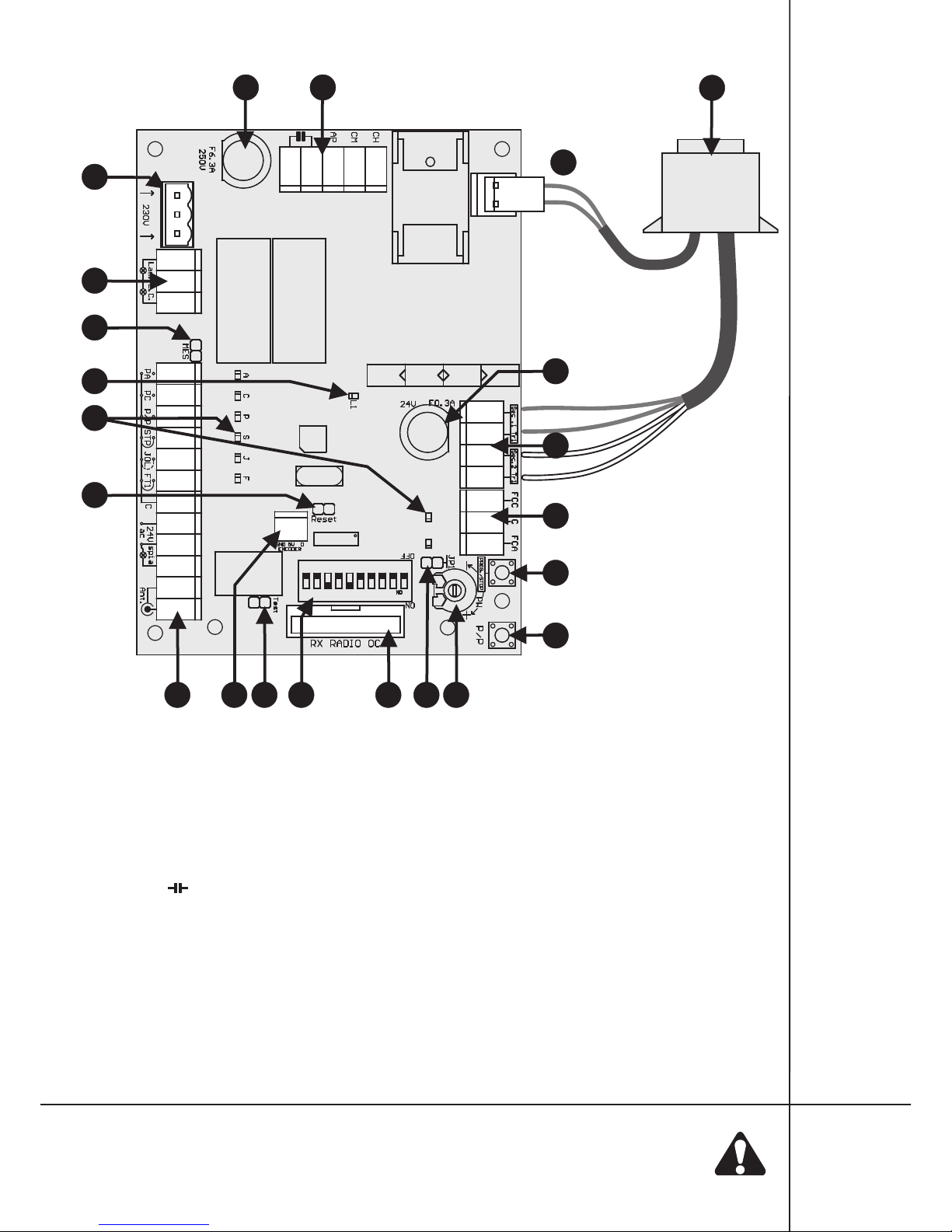
4.3.13.Connector forTRX radio card and clamps for connecting radio aerial (14, fig.1)
The driver has radio card TRX series connector and aerial input of the radio receiver. Connection and
descriptionof the card is inTRX card manual.
5. Driver operation description
After switching the power supply of the driver, there is an automatic change intoOPERATION MODE. In
operationmode, the current state of inputsis signaledby LED diodes(16, fig.1)
The programming takes place with the help of the LED L1 diode and PROG/STOP and P/P buttons which
are on the driver board (6.7 fig. 1), groups of DIP-SWITCH micro switches (11 fig. 1), JP1 jumper and PW
potentiometer (9 and 8 fig. 1).The control panel learns the operation times and pause during the procedure of the
programming. Programming procedure includes repeated operation with using the P/P button or remote
controlif such was assigned. Important remarksbefore the programming:
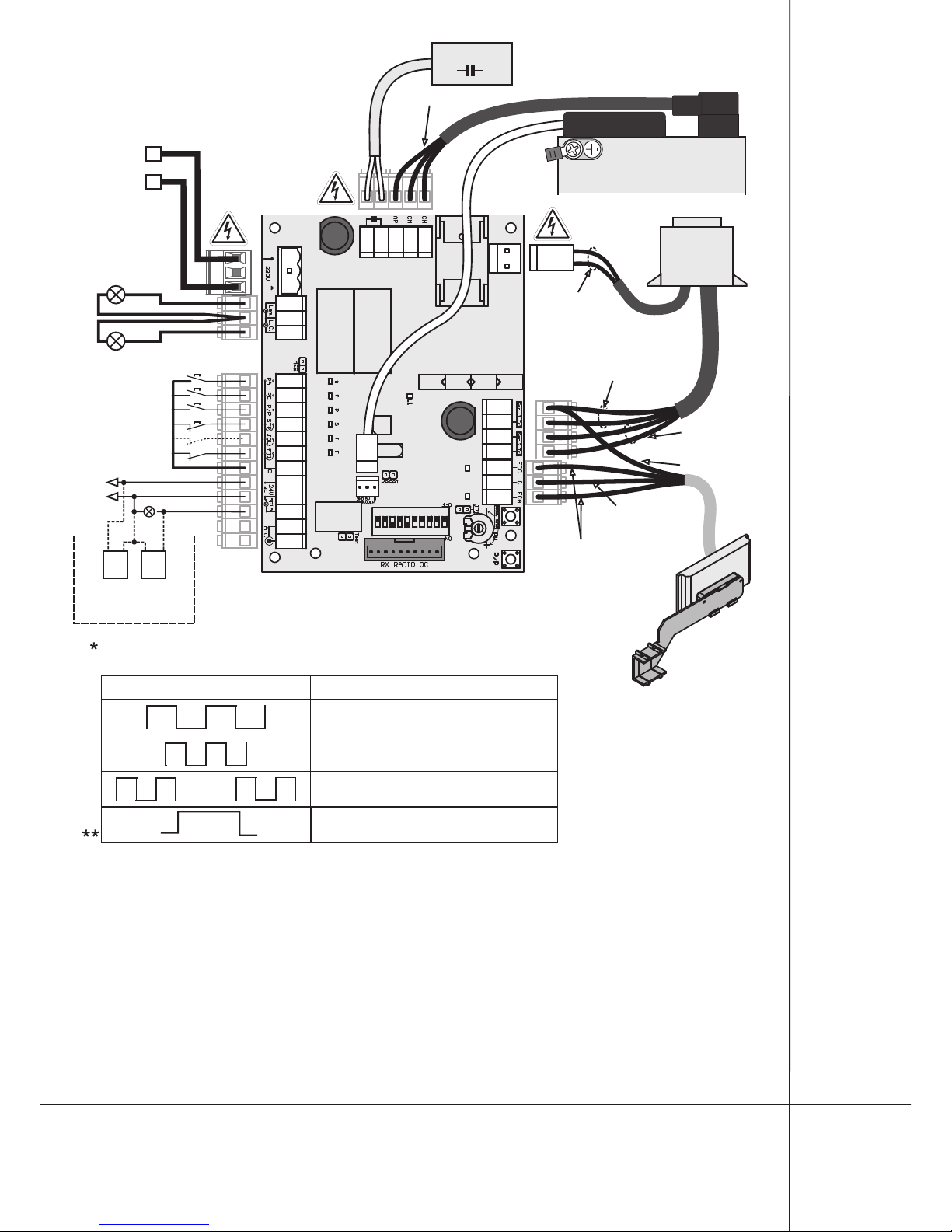
4Connect the power supply to the control panel and check if inputs work correctly by inspecting appropriate
diodes(diodesofNCcontactsmust shine).
4Removealltheobstaclesfromthegate operation zone.
4Diodes of the limit switch must be lighted when the gate is half opened.When the gate is moving to the closed
position the LED FCC diode must go out, the second FCA diode must go out when the gate reaches opened
position.
4Inorder conduct the successfulprocess of the driver programming keepthe following order:
4analysetables with individual settings of DIP-SWITCHesandto choose appropriate functions, see tab.1;
4programmeoperation time of the gate;
4makepossibleregulationsofthetraction force with the PW potentiometer;
4checkthe accuracyofoperationand repeat the programming if needed.
6.1. SIMPLE mode of learning
It is simple and fast form of setting times of closing, opening, auto-closing. Slowing times before total
openingand closing are set automatically. Programme according to following steps (fig. 3):
4manuallyplacethe gate in the middle ofthe way(1, fig.3).
4press PROG/STOP button and hold it pressed for about 3 seconds, until L1 diode does not light constantly (2,
fig.3).Driver is in the programming mode.
4Press P/P button. The gate will start moving in direction toward closing (3, fig.3). If the gate moves on the
direction towards opening it is necessary to change the direction of engine operation and limit switch
operation,see pt. 4.3.2-4.3.3.
4the gate reaches closed position (4, fig.3) and it starts opening automatically (5, fig.3), stopping at the
outermostopening position (6, fig.3).Thedriver starts remembering the auto-closing time (see tab.1).
4when the demanded pause time is complete, press P/P button.The motor will start closing (7, fig.3), finishing at
theoutermost closing position. L1 diode turnsoff,the end of programming procedure (8, fig.3)
6.2. EXTENDED mode learning
This procedure requires a little bit more involvement in the process the learning from the installer, than
in the case of the simple mode.The installer is able to set additionally the times of slowing down at opening and
closing according to personal needs. In order to set different zones of slowing down, act in the following way (fig.
3):
4manuallyplacethe gate in the middle ofthe way(1, fig.3).
4press PROG/STOP button and hold it pressed for about 5 seconds, until L1 diode does not light constantly (2,
fig.3).Driver is in the programming mode.
4Press P/P button. The gate will start moving in direction toward closing (3, fig.3). If the gate moves on the
direction towards opening it is necessary to change the direction of engine operation and limit switch operation,
seept. 4.3.2-4.3.3.
4thegate reaches closed position (4, fig.3)and it startsopeningautomatically(5,fig.3).
4whileopening, before the full opening ofthegatepressP/Pbutton in the position ofrequired slowingdown (6a,
fig.3).The gate stopsfor amoment andthen continuesand finishesthe opening.
4after stopping at the outermost opening position the driver starts remembering the auto-closing time (6,
fig.3).
4whenthe demanded pause time is complete, pressP/P button.Themotorwill start closing (7, fig.3).
6. Programming of SWIFT6-CB driver
8