DTM System MEMO User manual

SERVICE PROGRAMMER
MEMO
user manual
MEMO PROGRAMMER SOFTWARE
MEMO MANAGER
v1.1
user manual v1.1
automation systems

TABLE OF CONTENTS
I. MEMO - SERVICE PROGRAMMER .................................................3
1. General information . . . . . . . . . . . . . . . . . . . . . . . . . . . . . . . . . . . . . . . . . . . . . . . . . . . 3
2. Technical data. . . . . . . . . . . . . . . . . . . . . . . . . . . . . . . . . . . . . . . . . . . . . . . . . . . . . . . . 3
3. Elements of the programmer . . . . . . . . . . . . . . . . . . . . . . . . . . . . . . . . . . . . . . . . . . . . 3
4. Receiver management through the MEMO . . . . . . . . . . . . . . . . . . . . . . . . . . . . . . . . . 4
4.1. MEMO connection to the receiver . . . . . . . . . . . . . . . . . . . . . . . . . . . . . . . . . . . 4
4.2. Remotes / numbers backup to MEMO . . . . . . . . . . . . . . . . . . . . . . . . . . . . . . . . 4
4.3. Remotes / numbers write to receiver . . . . . . . . . . . . . . . . . . . . . . . . . . . . . . . . . 5
4.4. Receiver software update . . . . . . . . . . . . . . . . . . . . . . . . . . . . . . . . . . . . . . . . . 7
5. Registration of operations . . . . . . . . . . . . . . . . . . . . . . . . . . . . . . . . . . . . . . . . . . . . . . 8
6. MEMO code table. . . . . . . . . . . . . . . . . . . . . . . . . . . . . . . . . . . . . . . . . . . . . . . . . . . . . 9
II. MEMO MANAGER - MEMO SOFTWARE. . . . . . . . . . . . . . . . . . . . . . . . . . . . . . . . . . . . . . . . . . . 10
1. Usage . . . . . . . . . . . . . . . . . . . . . . . . . . . . . . . . . . . . . . . . . . . . . . . . . . . . . . . . . . . . 10
2. Hardware requirements . . . . . . . . . . . . . . . . . . . . . . . . . . . . . . . . . . . . . . . . . . . . . . . 10
3. Installation and start-up . . . . . . . . . . . . . . . . . . . . . . . . . . . . . . . . . . . . . . . . . . . . . . . 10
4. Connecting MEMO to a computer. . . . . . . . . . . . . . . . . . . . . . . . . . . . . . . . . . . . . . . . 10
5. Program main window . . . . . . . . . . . . . . . . . . . . . . . . . . . . . . . . . . . . . . . . . . . . . . . . 10
5.1. CONTROL GSM tab . . . . . . . . . . . . . . . . . . . . . . . . . . . . . . . . . . . . . . . . . . . . . 12
5.1.1. Editing numbers and receiver configuration . . . . . . . . . . . . . . . . . . . . . . 13
5.2. RADIO RECEIVERS tab . . . . . . . . . . . . . . . . . . . . . . . . . . . . . . . . . . . . . . . . . . 15
5.2.1. Editing remote control files . . . . . . . . . . . . . . . . . . . . . . . . . . . . . . . . . . 16
5.3. FIRMWARE tab . . . . . . . . . . . . . . . . . . . . . . . . . . . . . . . . . . . . . . . . . . . . . . . . 18
automation systems

I. MEMO - SERVICE PROGRAMMER
1. GENERAL INFORMATION
MEMO is a service programmer designed to work with selected DTM System receivers. Using the
programmer allows you to save remote controllers memory or telephone numbers memory from the
receiver to a file, enter remote controllers or telephone numbers to the receiver memory from a file, and
update the receiver firmware.
2. TECHNICAL DATA
power supply 3,3 - 5V, via USB or receiver
storage capacity 2 MB
external dimensions of the housing 75x45x15 mm
3. ELEMENTS OF THE PROGRAMMER
3
MicroUSB SOCKET
for powering the device,
communication with PC
and receiver
BACKUP LED
green
WRITE LED
red
UPDATE LED
orange
BACKUP button
WRITE button
UPDATE button
Fig.1. View of the MEMO service programmer with description of the elements.

4. RECEIVER MANAGEMENT THROUGH MEMO PROGRAMMER
4.1.MEMO CONNECTION TO THE RECEIVER
The programmer should be connected to the receiver using the USB cable included in the set. The
programmer's readiness for operation is signaled by blinking of the BACKUP, WRITE and UPDATE LEDs.
During connection with the receiver the programmer buttons are active.
4.2. REMOTES / NUMBERS BACKUP TO MEMO
In order to create keyfob / numbers memory file:
źconnect the MEMO programmer to the receiver. The BACKUP, WRITE and UPDATE LEDs will begin to
flash to indicate that the programmer is ready for operation.
źpress the BACKUP button. Ongoing recording is signaled by a flashing green BACKUP LED. The end of
the recording is signaled by the blinking of the BACKUP, WRITE and UPDATE LEDs.
When saving the remote / number memory do not disconnect the MEMO programmer from the
receiver.
If errors occurred during recording, the green BACKUP LED will flash cyclically to indicate the error code
(see section 6).
The backup file with memory of remote controls / receiver numbers is saved in the MEMO programmer. It
gets the name RD_xxxxx.RRF, where "xxxxx" is the file's serial number. Each subsequent saved remote
controls / number memory file will receive a name with the next number. The files can be edited after
connecting the MEMO programmer to the computer in the MEMO MANAGER program (see the MEMO
MANAGER manual).
Deleting a file from the programmer's memory does not affect the order of numbering. The device
searches for the highest busy number and assigns the new file a sequential number.
When the highest number 99999 is busy, MEMO will report an error and the remotes / numbers will fail to
register. In this case, you must organize the files in memory using the MEMO MANAGER program - rename
or delete files.
fIG. 2. Remotes / numbers backup to MEMO.
4ALL LEDS BLINK
SAVING FILE COMPLETED
3BACKUP LED BLINKS
RECORDING IN PROGRESS
2ALL LEDS PULSE
PUSH THE BACKUP BUTTON
1CONNECT MEMO TO
RECEIVER VIA USB CABLE
868
433
PWR
C1
C2
MOM
MONO
BIST
G/LOCK
4

4.3. REMOTES / NUMBER WRITE TO RECEIVER
To write remotes / numbers:
źconnect the MEMO programmer to the receiver. The BACKUP, WRITE and UPDATE LEDs will begin to
flash to indicate that the programmer is ready for operation.
źpress the WRITE button. MEMO will first create an emergency backup of the receiver's memory. It is
signaled by a fast pulsing of the green BACKUP diode and lighting of the red WRITE diode. Then, the
process of saving remote controls / numbers to the receiver's memory will start. This is indicated by the
green BACKUP diode going off and the red WRITE diode pulsing. The end of the recording is signaled by the
blinking of the BACKUP, WRITE and UPDATE LEDs.
When writing remote controls / numbers from a file, do not disconnect the MEMO programmer
from the receiver.
Only the remote memory is copied from radio receivers. The GSM number memory and receiver
settings are copied from GSM receivers.
If errors occurred during the recording, the red WRITE diode will flash cyclically to indicate the error code
(see item 6).
The remotes / numbers from the receiver's memory will be replaced with remotes / numbers
entered from the file.
The process of writing remote controls / numbers to the receiver is preceded by creating an emergency
backup called AUTOBACK.RRF. Creating an emergency backup does not affect the remote memory
storage process.
If errors appear during backup, the process will be interrupted and the green BACKUP LED will flash
periodically to indicate an error code (see section 6).
After saving the remote controls to the receiver's memory, it is necessary to synchronize the rolling
counters of the remote controls with the receiver. When using the remote control with the receiver
for the first time, press the remote control button twice.
1CONNECT MEMO TO
RECEIVER VIA USB CABLE
868
433
PWR
C1
C2
MOM
MONO
BIST
G/LOCK
5ALL LEDS BLINK
RECORDING TO
RECEIVER COMPLETED
3BACKUP LED BLINKS
WRITE LED ON
RECORDING AUTOBACK.RRF
2ALL LEDS PULSE
PUSH THE WRITE BUTTON
4WRITE LED BLINKS
RECORDING REMOTES/
NUMBERS TO RECEIVER
Fig. 3. Remotes / numbers write to the receiver.
5

In the receiver's memory, remotes / numbers from the file set in the MEMO MANAGER program as the
main one are first entered (see the MEMO MANAGER instruction).
If no file is set as the main one, the MEMO programmer will use the remotes / numbers file with the highest
number for saving, i.e. the file of recently remembered remotes / numbers.
It is possible to skip the main file and select the most recent remotes / numbers to save the file.
The procedure can be used for simple transfer of remote control memory / numbers between
receivers.
In order to enter to the receiver the last saved remotes / numbers and configuration of the GSM receiver,
bypassing the main file, you should:
źconnect the MEMO programmer to the receiver. The BACKUP, WRITE and UPDATE indicator LEDs will
begin to flash to indicate that the programmer is ready for operation.
źpress and hold the WRITE button for more than 3 seconds.
źrelease the WRITE button when the red WRITE LED goes off. MEMO will first create an emergency
backup of the receiver's memory. It is signaled by a fast pulsing of the green BACKUP diode and lighting of
the red WRITE diode. Then the process of saving the remote controls to the receiver's memory will start.
This is indicated by the green BACKUP diode going off and the red WRITE diode pulsing. The end of the
recording is signaled by the blinking of the BACKUP, WRITE and UPDATE LEDs.
When entering remote controls / numbers from a file, do not disconnect the MEMO
programmer from the receiver.
If errors occurred during the recording, the red WRITE diode will flash cyclically to indicate the error code
(see item 6).
1CONNECT MEMO TO
RECEIVER VIA USB CABLE
868
433
PWR
C1
C2
MOM
MONO
BIST
G/LOCK
7ALL LEDS BLINK
RECORDING TO RECEIVER
COMPLETED
3HOLD THE WRITE BUTTON
UNTIL THE LED TURNS OFF
2ALL LEDS BLINK
PUSH AND HOLD
WRITE BUTTON
6WRITE LED BLINKS
RECORDING TO RECEIVER
fIG. 4. Recording of remotes / numbers and configuration of the GSM receiver using the last created file.
4RELEASE THE WRITE
BUTTON WHEN THE LED
TURNS OFF
5BACKUP LED BLINKS
WRITE LED ON
RECORDING AUTOBACK.RRF
6

4.4. RECEIVER SOFTWARE UPDATE
To update the receiver firmware it is necessary to have a firmware file. The files should be
downloaded using the MEMO MANAGER program (see the MEMO MANAGER manual).
MEMO can contain many firmware files for different receivers. The MEMO programmer recognizes the
model and software version of the receiver to which it is connected. On this basis, the programmer selects
which of the available files to use for updating.
To update the receiver software:
źconnect the MEMO programmer to the receiver. The BACKUP, WRITE and UPDATE indicator LEDs will
begin to flash to indicate that the programmer is ready for operation.
źpress the UPDATE button. The orange UPDATE LED will flash to indicate that the software has been
updated. The end of the update is signaled by the blinking of the BACKUP, WRITE and UPDATE LEDs.
źThe receiver resets and restarts.
During the software update, do not disconnect the MEMO programmer from the receiver.
If errors occurred during the update, the orange UPDATE diode will flash periodically to indicate the error
code (see section 6). Depending on what error the receiver has, it can reset and run with the old version of
the software or remain in the software update mode. In this case, repeat the software update process.
In the software update procedure, the MEMO programmer always selects the latest firmware version
available on the device. If the receiver firmware version is newer than available in the MEMO programmer
memory, the programmer expects confirmation of the operation of uploading the older version of the
software. The waiting state is signaled by the steady cyclic blinking of the orange UPDATE diode.
Confirmation is made by pressing the UPDATE button again. The operation is canceled by pressing one of
the other two BACKUP or WRITE buttons.
1CONNECT MEMO TO
RECEIVER VIA USB CABLE
868
433
PWR
C1
C2
MOM
MONO
BIST
G/LOCK
5RECEIVER RESET
3UPDATE LED BLINKS
UPDATE IN PROGRESS
2ALL LEDS PULSE
PUSH THE UPDATE BUTTON
4ALL LEDS PULSE
UPDATE COMPLETED
868
433
PWR
C1
C2
MOM
MONO
BIST
G/LOCK
Fig. 5. Receiver firmware update.
7

5. REGISTRATION OF OPERATIONS
Each operation performed by the MEMO programmer is recorded in the log.txt file, available after
connecting MEMO to the computer.
The file contains basic information about the course of operations, such as: receiver type, firmware
version, file name, operation status, type and error code.
The report on operations is as follows:
Device type: specifies the device type
Firmware version: receiver firmware version
File name: name of the file in the MEMO memory used during the operation
File device type: the type of device the file is for (only for firmware)
File firmware version: file firmware version (for firmware files)
Status: additional information about the result of the operation
Error code: error code (00 means no error)
Fig. 6. Sample of log.txt file.
8

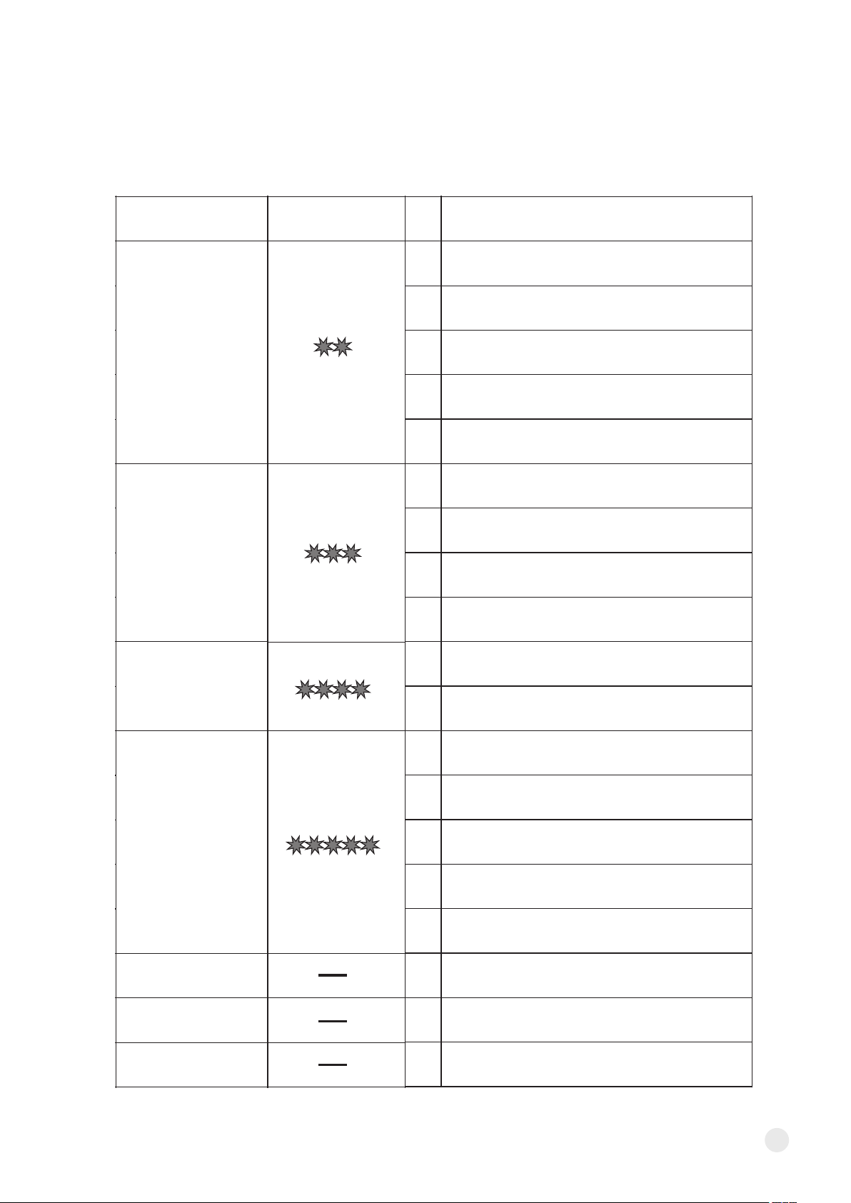
6. MEMO PROGRAMMER CODE TABLE
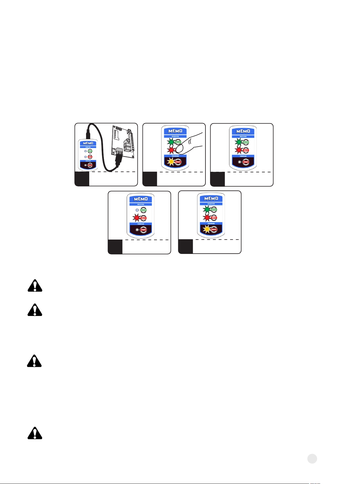
In the case of errors during the backup operation to the MEMO, write to the receiver, firmware updates,
one of the LEDs BACKUP, WRITE, or UPDATE (depending on the operation being performed) will
periodically blink, the blink indicates the amount of the type of error (Table 1). The error code is recorded in
the log.txt file (see item 5).
9
the communication line has not been released
by the receiver
the receiver could not be identified
(no readable communication was established)
the receiver is not ready for programming
(did not accept the data package)
timeout during transmission
(communication interrupted)
frame retry limit exceeded
(illegible transmission)
internal file system error
unable to read / write file
corrupt firmware file
checksum error
internal file system error
unable to create directory
unable to write data to file
full memory
brak pliku firmware dla podłączonego odbiornika
no firmware files
error creating automatic backup autobackup
no file for write operation
(WRITE)
unable to create name for new file
(operation BACKUP)
error while reading remotes / numbers,
incorrect checksum, repetition limit exceeded
error while saving to receiver memory
no confirmation of receipt of data
aktualizacja oprogramowania zakończona sukcesem
saving memory to file successful
successfully entering the remotes / numbers
into the receiver's memory
COMMUNICATION
ERROR
FILE SYSTEM
ERROR
NO FIRMWARE
FILE
READ WRITE
FILE ERROR
PROGRAM
SUCCESS
READING
SUCCESS
WRITING
SUCCESS
ISSUE
CODE
NUMBER
OF BLINKS
ERROR
NAME
01
02
03
04
05
01
02
03
04
01
02
01
02
03
04
05
00
00
00
Tab. 1. MEMO service programmer code table.

II. MEMO MANAGER - MEMO SOFTWARE
1. USAGE
MEMO MANAGER is a computer program designed to support the MEMO service programmer. The
program allows you to manage files used in working with the MEMO service programmer and edit the
contents of remote memory / number files. MEMO MANAGER software ensures full compatibility between
systems thanks to the support of remote controls files from various receiver models.
2. HARDWARE REQUIREMENTS
- a PC with MS Windows® version NT / XP / Vista / 7/8/10
- .net framework version 4.0 or higher required to be installed
3. INSTALLATION AND START-UP
Run the installation file Memo_setup.exe. The file is available for download on the manufacturer's website
www.dtm.pl. During installation, follow the program installer's guidelines. After installing the software,
start the MEMO MANAGER program and connect the MEMO programmer.
4. CONNECTING THE MEMO PROGRAMMER TO A COMPUTER
The programmer should be connected to the computer using the USB cable included in the set. The
programmer's readiness for operation is signaled by blinking of the BACKUP, WRITE and UPDATE LEDs.
During the connection with the computer the programmer buttons are inactive.
The MEMO programmer is recognized by the Windows® operating system as a mass memory with a
capacity of approx. 2 MB, from which you can read or write files. No driver installation required.
To operate the MEMO service programmer, it is recommended to use dedicated software -
MEMO MANAGER.
The power supply and readiness for operation is indicated by the pulsing of the BACKUP, WRITE and
UPDATE LEDs on the MEMO service programmer panel.
10

5. MAIN WINDOW OF THE PROGRAM
The main window consists of three tabs:
- CONTROL GSM - designed for managing telephone memory files and configuring the Control GSM
receiver
- RADIO RECEIVERS - designed for managing memory files of radio receivers
- FIRMWARE - designed for managing receivers firmware update files
The window of each of the tabs is divided into two parts.
Files located in the local directory on the user's computer are displayed on the left. The local directory is a
strictly defined location where the program stores remote control memory files and firmware files.
On the right, files stored in the MEMO programmer's memory are displayed.
Connection of the MEMO programmer and proper communication of the program with a computer is
indicated by the icon, the lack of connection is indicated by the icon.
CONTROL GSM
TAB
RADIO RECEIVERS
TAB
FIRMWARE
TAB
FILE COPY BUTTONS
LANGUAGE
SELECTION
ABOUT PROGRAM
DESCRIPTION
OF COLORS
OF FILES
LOCAL FILES MEMO FILES
Fig. 1. View of the MEMO MANAGER main window.
CONNECTION
STATUS ICON
11
FROM PC TO MEMO
FROM MEMO TO PC

5.1. CONTROL GSM TAB
The CONTROL GSM tab allows you to manage phone numbers memory files and configure the receiver.
Description of buttons and functions of the CONTROL GSM tab
opens a folder with local files
creates a new empty number and receiver configuration file
saves the file to a location on your computer
launches the file editing window
deletes selected files
creates a quick copy of the selected file
allows you to change the file name and description
displays information about the operations from the log.txt file
allows to set the default file used by MEMO to write to the receiver
when the WRITE function is used
Fig. 2. Main window view - CONTROL GSM tab.
12

5.1.1. EDITING NUMBER FILES AND CONFIGURATION OF THE RECEIVER
The MEMO MANAGER program allows you to modify the contents of the subscriber numbers memory and
receiver configuration in a file. After pressing the EDIT button, the file editing window appears with two
tabs:
źSUBSCRIBERS TAB- from the tab level you can add, edit or delete subscribers.
You can import a CSV file with phone numbers, which will save you the time by entering each number
manually. To import a CSV file, create a new file and enter edit options, or edit an existing file. In the
Subscribers tab, press "Import subscribers from CSV file". A window will open in which you should select in
turn: separator character, column with description, column with phone number and prefix number and
then press the "Import" button. The numbers will be imported into the file.
13
Fig. 3. View of the subscribers edition window from the CONTROL GSM receiver file.
Fig.4. View of the import window from a CSV file.

źDEVICE SETTINGS TAB - from the tab you can configure the settings of the receiver.
When creating and editing a file for a Control GSM receiver, make sure that both the
Subscribers and Device settings tabs contain the correct values. The receiver stores the data
of number memory and receiver configuration.
14
Fig. 5. View of the CONTROL GSM receiver settings edition window.

5.2.RADIO RECEIVERS TAB
The RADIO RECEIVERS tab allows you to manage remote control memory files.
Description of buttons and functions of the RADIO RECEIVERS tab
opens a folder with local files
creates a new empty remote controls memory file
saves the file to a given location on your computer
allows you to save the file in FLEX .cfbi file format
allows you to save the file in .csv format
launches the file editing window
deletes selected files
creates a quick copy of the selected file
allows you to change the file name and description
displays information about the operations from the log.txt file
allows to set the default file used by MEMO to write to the receiver
when the WRITE function is used
15
Fig. 6. Main window view - RADIO RECEIVERS tab.

5.2.1. EDITING REMOTE FILES
The MEMO MANAGER program allows you to modify the contents of remotes memory contained in the
file. After pressing the EDIT button, the remote controls file editing window appears, from which you can:
- delete remote controls
- add remote controls from other files
- change the configuration of button connections with channels
- change the position of remote controls in the memory
removes the remote control from the list
copies the remote control to the program clipboard
copies the remote control to the clipboard and removes it from the list
displays the remote control editing window in which you can change the position
of the remote control in the memory and configure links between remote control buttons
and the receiver channels
Description of the remote editing buttons:
Fig. 7. Window for editing the contents of remote control files.
16

Description of buttons and functions of the „File edition”:
adds remotes from another file to the list
saves the current file
activates the remote edit buttons
displays the remote control editing window in which you can change
the position of the remote control in the memory and configure links between remote
control buttons and the receiver channels
removes the remote control from the list
copies the remote control to the program clipboard
copies the remote control to the clipboard and removes it from the list
button visible when there are remote controls in the clipboard,
clicking activates the clipboard options
adds remotes from the clipboard to the list
removes remotes from the clipboard
shows the contents of the clipboard and allows you to delete
selected remotes
closes the editor window
17

5.3.FIRMWARE TAB
From the FIRMWARE tab you can download the latest receiver firmware available on DTM System servers
and manage these files.
The downloaded firmware can be downloaded to the appropriate radio receiver.
Description of buttons and functions of the FIRMWARE tab
opens a folder with local files
allows you to add a firmware file to the directory from any location
specified by the user
opens a window from which you can download the selected firmware
available on the DTM System servers (internet connection required)
deletes selected files
opens a window that allows filtering by: file name,
receiver to which the firmware is dedicated, firmware version
Fig. 8. Main window view - FIRMWARE tab.
18

DTM System hereby declares that the device
complies with Directive 2014/30 / EU. The full text of
the EU declaration of conformity is available at the
Internet address.
DISPOSAL
Electrical or electronic devices cannot be
removed with everyday waste. The correct
recycling of devices gives the possibility of
keeping natural resources of the Earth for
a longer time and prevents the degradation of
natural environment.
DTM System provides operational and ready to use devices.
The producer gives 24 months warranty from the selling date
to the end customer. This time is counted according to the
producer warranty labels or serial numbers placed on every
product. Producer obliges himself to repair the device for
free if during the warranty period there are problems which
come because of his fault. Broken device should be supplied
on customer’s expense to the place of purchase and enclose
clear and brief description of the breakage. The cost of
mount/dismount is covered by the user. The warranty does
not cover: batteries in the remote controls, faults caused by
improper usage, user self repairs and adaptations, lightning
strikes, voltages or short circuits in the electrical grid.
Appropriate legal acts regulate details of the warranty.
WARRANTY CONDITIONS
Table of contents
Other DTM System Industrial Equipment manuals
Popular Industrial Equipment manuals by other brands

Cincinnati
Cincinnati CL-6 3000 Operation, safety and maintenance manual

Siemens
Siemens 3VA9131-0QB00 operating instructions

ABB
ABB PowerCube PB/F Installation and service instructions

VS
VS DATAGONE LG-PLUS operating manual

TE Connectivity
TE Connectivity Raychem EPP-0001-INT-1/12 Installation instruction

GE
GE RAB8116B installation instructions

Danfoss
Danfoss Brazed Plate Heat Exchanger operating guide

Siemens
Siemens SIMATIC NET S7-1500 operating instructions

Jenex
Jenex XLA98 instructions

BIG
BIG Point Master Pro PMPC Series Operation manual

Siemens
Siemens 8MF1 Series operating instructions

morse
morse M Series Installation and maintenance instructions