TE RBK-X1 Reference guide

1 P a g e | 1
111
Page | 1
Customer Manual
RBK-X1 / RBK-X1C Heat Shrink Machine
Operating manual no. 409-35022
Language: English
Rev: B

RBK-X1 / RBK-X1C
Rev. B Jun. 2021
1
RAYCHEM are trademarks of TE Connectivity.
All of the information in this manual, including illustrations, is believed to be reliable. Users,
however, should independently evaluate the suitability of each product for their application.
TE Connectivity /Raychem make no warranties as to the accuracy or completeness of the
information and disclaim any liability regarding its use.
TE Connectivity/Raychem only obligations are those in the Standard Terms and Conditions of Sale
for this product and in no case will TE Connectivity/Raychem are liable for any incidental, indirect or
consequential damages arising from the sale, resale, use or misuse of the product.
TE
Connectivity/Raychem
Specifications are subject to change without notice. In addition, TE
Connectivity reserve the right to make changes in materials or processing, without notification to
Buyer, which do not affect compliance with any applicable specification.
No part of this manual may be reproduced or transmitted in any form or by any means, electronic or
mechanical, including photocopying, or recorded by any information storage or retrieval system,
without written permission from TE.
The original operating manual has been written in English.

RBK-X1 / RBK-X1C
Rev. B Jun. 2021
2
Disposal: RBK processor (RBK-X1 & RBK-X1C)
This product must not be disposed of as municipal waste.
Amendment Record
Rev.
Content
Amended By
Date
Change
Request No.
Rev. A
Initial Release
Cham Zhu
Nov. 2020
Rev. B
Involve X1 and X1C, CE
version and NON-CE version
Cham Zhu
Jun. 2021

RBK-X1 / RBK-X1C
Rev. B Jun. 2021
3
Table of Contents
1 I
n
t
r
odu
c
t
i
on
...................................................................................................................................................... 5
1.1 General Information ................................................................................................................................... 6
1.2 Front Panel.................................................................................................................................................. 7
1.3 Front Panel-Touch Screen........................................................................................................................... 9
1.4 Rear Panel................................................................................................................................................. 11
2 Safety ................................................................................................................................................................ 14
2.1 General Warnings ..................................................................................................................................... 14
2.2 Electrical Safety......................................................................................................................................... 15
2.3 Personal Safety ......................................................................................................................................... 16
2.3.1 Eyes ................................................................................................................................................... 16
2.3.2 Clothing............................................................................................................................................. 16
2.3.3 Fire Hazard........................................................................................................................................ 16
2.3.4 Hot Surfaces...................................................................................................................................... 16
2.3.5 Damage............................................................................................................................................. 16
2.3.6 Servicing............................................................................................................................................ 16
2.4 Warnings and Labels ................................................................................................................................. 17
3 Software............................................................................................................................................................ 18
3.1 Heat parameter ........................................................................................................................................ 20
3.2 Sequence production................................................................................................................................ 21
3.3 Sequence Setting ...................................................................................................................................... 22
3.4 Production Setting .................................................................................................................................... 23
3.5 Maintenance............................................................................................................................................. 24
3.6 Auto Calibration........................................................................................................................................ 26
3.7 Manual Calibration ................................................................................................................................... 27
3.8 Remote Operation Mode.......................................................................................................................... 28
3.8.1 Remote operation Procedure............................................................................................................. 28
3.8.2 RS232 Data Format ........................................................................................................................... 29
3.9 System Parameter..................................................................................................................................... 30
3.10 Error Log ................................................................................................................................................... 31
3.11 Circle Test.................................................................................................................................................. 32
3.12 I/O & Manual ............................................................................................................................................ 32
3.13 Centering Manual ..................................................................................................................................... 33
3.14 Barcode scanning...................................................................................................................................... 34
3.15 Data Collection.......................................................................................................................................... 35
4
Installation
and O
p
e
r
a
t
i
on
............................................................................................................................ 36
4.1 Installation ................................................................................................................................................ 36
4.1.1 Unpacking ......................................................................................................................................... 36
4.1.2 Safety ................................................................................................................................................ 36
4.1.3 Location ............................................................................................................................................ 36
4.1.4 Electrical Connections....................................................................................................................... 36
4.1.5 Pneumatic Connections .................................................................................................................... 36

RBK-X1 / RBK-X1C
Rev. B Jun. 2021
4
4.2 Operation mode ....................................................................................................................................... 37
4.2.1 Stand-by mode.................................................................................................................................. 37
4.2.2 Single Process mode (Main Interface) ---- See section 4.2.7 ............................................................ 37
4.2.3 Sequence Production mode ---- See section 3.2 & 3.3..................................................................... 37
4.2.4 Remote Operation mode ---- See section 3.8 ................................................................................... 37
4.2.5 Auto Centering mode (Main Interface) ---- See section 4.2.8 .......................................................... 37
4.2.6 Switch ON/OFF to processor............................................................................................................. 38
4.2.7 Single Process Operation .................................................................................................................. 39
4.2.8 Auto Centering Operation ................................................................................................................ 40
4.2.9 Emergency Stop ................................................................................................................................ 41
4.2.10 Heater Carriage Jammed .................................................................................................................. 42
4.2.11 Emergency Heater Chamber Release................................................................................................ 43
4.2.12 Routine Maintenance ....................................................................................................................... 44
4.3 Troubleshooting........................................................................................................................................ 45
4.3.1 Preliminary Checks............................................................................................................................ 45
4.3.2 Troubleshooting Table ...................................................................................................................... 45
4.4 Recommended Spare Parts....................................................................................................................... 48
4.5 Repair........................................................................................................................................................ 53
4.5.1 Circuit Protection Devices................................................................................................................. 53
4.5.2 Gaining Access .................................................................................................................................. 54
4.5.3 Heater Element Replacement........................................................................................................... 57
4.6 OPTIONAL ACCESSORIES........................................................................................................................... 58
4.6.1 Calibration tools.................................................................................................................................. 58
4.6.2 Power Cord & Transformer............................................................................................................... 58
4.6.3 RBK Fixture........................................................................................................................................ 59
4.6.4 Air Cooled Stub splice fixture............................................................................................................ 59
4.6.5 Other accessories.............................................................................................................................. 60
4.6.6 MES Customized ............................................................................................................................... 60
5 Specification...................................................................................................................................................... 61
6
Schematic Diagram
..................................................................................................................................... 62
7 Pneumatic Diagram........................................................................................................................................... 71
8 Address "After" Sales. ....................................................................................................................................... 72
9 RoHS information.............................................................................................................................................. 72
10 Declaration of conformity of CE ........................................................................................................................ 73

RBK-X1 / RBK-X1C
Rev. B Jun. 2021
5
1 I
n
t
r
odu
c
t
i
on
This manual applies to RBK-X1 and RBK-X1C processor:
(In this manual RBK processor will stand for both RBK-X1 and RBK-X1C):
RBK-X1
----NON-CE version
TE PN: 2234800-1
----CE version
TE PN: 2234800-2
RBK-X1C
----NON-CE version
TE PN: 2376800-1
----CE version
TE PN: 2376800-2
Fig.1 General View
Customer can purchase optional Centering Device 2369600-1 to upgrade machine from RBK-X1
to RBK-X1C. Refer to Instruction Sheet 408-35126.

RBK-X1 / RBK-X1C
Rev. B Jun. 2021
6
1.1 General Information
The RBK processor is semi-automatic units using an infrared process to heat shrink TE Connectivity ILS-125,
ILS-85 and QSZH products onto ultrasonically welded or crimped splices.
The equipment is designed to operate in conjunction with ultrasonic welders, positioned adjacent to the welding
head.
The heat chamber takes ILS and QSZH products from size 1 to 3A and has electrically heated quartz glass
elements which provide the heat source, up to 550°C. Operation of the chamber is prevented until its
temperature is within 10°C (editable) of the set operating temperature.
Activated by two start buttons, the heating chamber moves forward, enclosing the joint area. It remains in place
for the set timed period, and then returns to the rear rest position, automatically ejecting the wire assembly with
the RBK-ILS splice sealing product installed.
In the event of a power failure the heating chamber is retracted to the rear rest position.
The RS232 interface, allows Time, Temperature and Product size to be transferred from a remote machine (e.g.
ultrasonic welding equipment) or control computer.
Ten pre-set memory buttons can be programmed for local storage of Time, Temperature and Product size.
These can be selected individually, or selected in a set sequence by the operator.
500°C is the maximum recommended set temperature.
Set the temperature close to or exceed upper limit 550°C, could cause
reduction to heater life.
RBK-X1 / RBK-X1C
Rev. B Jun. 2021
7
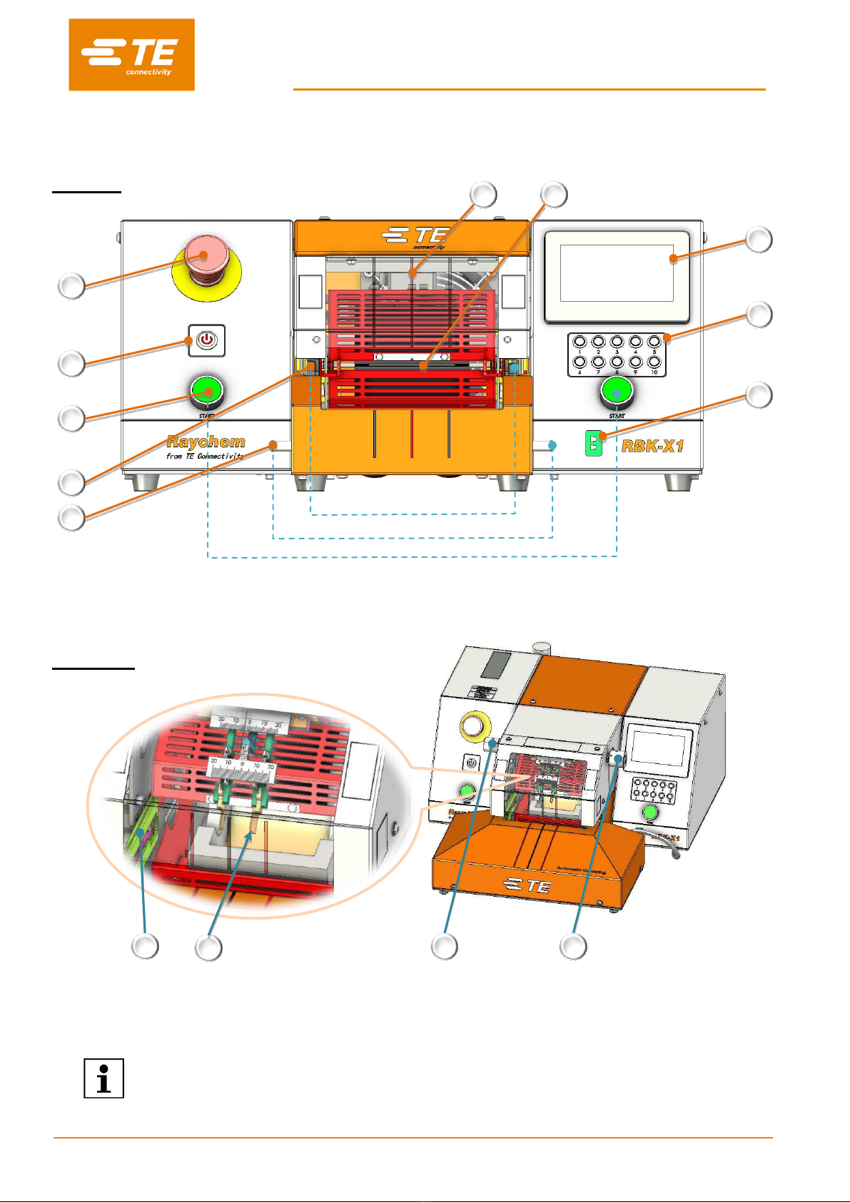
1.2 Front Panel
(Controls and Major Components)
RBK-X1
Fig.2 Front Pane
In Fig.2, Item 1~10, apply for both RBK-X1 & RBK-X1C. Item 11~14, apply only for RBK-X1C.
1
2
6
7
8
9
10
4
5
3
11
13
12
14
RBK-X1C

RBK-X1 / RBK-X1C
Rev. B Jun. 2021
8
1. Emergency Stop
(cuts power to processor)
2. I/O Switch
(Switch to heater. Off--standby, Flash—warm up, Lit—temperature reach set value)
3. Cycle Start Push buttons
(Press and hold both buttons simultaneously 0.5s to start cycle process.
Interrupt Cycle----see section 3.5 item4, when switch ON this function, during cycle, press both start button again, would
interrupt the cycle. Heater would back to home position at once.)
4. Grippers
(hold cable splice in heating chamber)
5. Dual Release
(allow removal of splice by hand)
6. Calibration Socket
(Connect to the UHI temperature probe, to access auto-calibration process.)
7. Process button
(10 editable pre-set Single Process Selection Button. Can store 3 parameter, product size/process time/process
temperature)
8. Touch screen
(Display processor working information. Can edit processor parameter after login on.)
9. Heater Chamber
(heat shrinks product over splice)
10. Centering Mark
(Designed to centering tube visually)
11. Centering Plate
(See section 4.2.8 Auto Centering operation.)
12. Detection Plate
(See section 4.2.8 Auto Centering operation)
13. Offset knob
(Pull left knob and rotate, to adjust the 2X detection plates to left or right. Range: “+/-10mm”)
14. Distance knob
(Pull right knob and rotate, to adjust the distance between 2X detection plate. Range: “5~20mm”)
RBK-X1 / RBK-X1C
Rev. B Jun. 2021
9
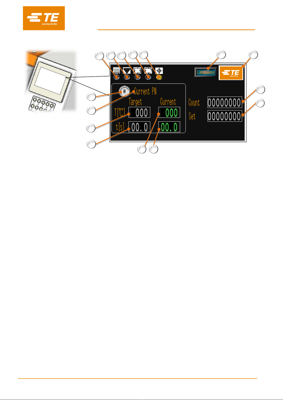
1.3 Front Panel-Touch Screen
Fig.3 Touch Screen (main interface)
This picture above is showing the main interface. Some other interfaces see section 3 SOFTWARE.
1. Heater Indicator
(Illuminated amber when heater start to warm up. Illuminated green when heater reach set value. Ready to production.)
2. Calibrate Indicator
(Illuminated when calibration required, meanwhile it will pop up reminder for calibration in the main interface.)
3. Cycle Indicator
(Illuminated when running cycle.)
4. Sequence Indicator
(Illuminated when access to Sequence Production mode)
5. Auto Centering Indicator (to activate in maintenance page, “Centering”)
RBK-X1, Normally OFF. When activated, processor would show error.
RBK-X1C, Normally OFF. When activated, this indicator would show in main page. Operator can operate the processor
with Auto Centering function when this indicator shown green. Indicator illuminated amber during cycle, illuminated red
when error.
6. Current process
(Display current selected process button number. 10X pre-set process buttons available.)
7. Current PN
(Display product size or PN stored in the current selected process button.)
8. Target Temperature
(Display Temperature stored in the current selected process button.)
9. Target time
(Display time stored in the current selected process button.)
10. Current Temperature
(Display the real Temperature of current cycle.)
11. Current time
(Display the real time of current cycle.)
2
1
3
4
6
7
8
9
12
13
5
15
14
10
11

RBK-X1 / RBK-X1C
Rev. B Jun. 2021
10
12. Target Quantity
(It will pop up reminder when production reach target quantity. See section 3.4 production setting.)
13. Production Counter
(See section 3.4 production setting)
14. Login on button
(TE logo. Login on to read more info or modify processor parameter. See section 3.)
15. Language shift button
RBK-X1 / RBK-X1C
Rev. B Jun. 2021
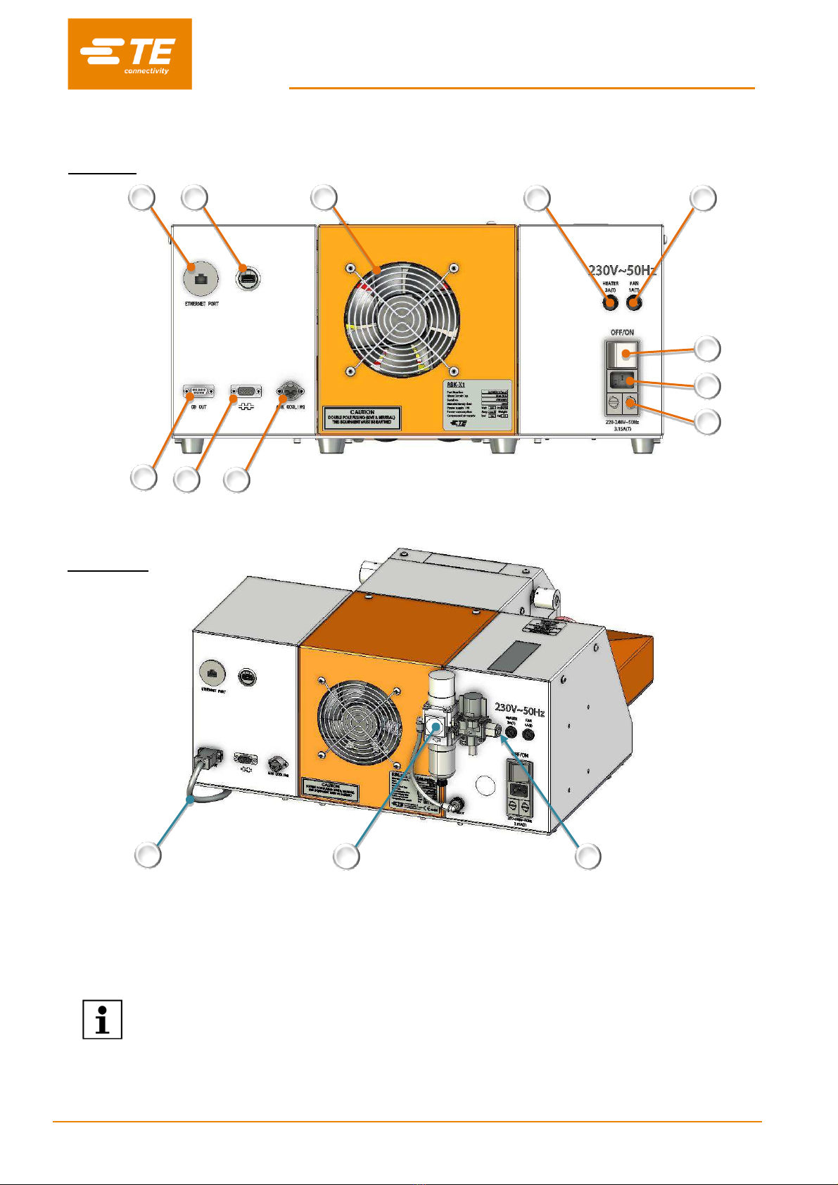
11
1.4 Rear Panel
RBK-X1
Fig.4 Rear Panel
In Fig.4, Item 1~11, apply for both RBK-X1 & RBK-X1C. Item 12~13, apply only for RBK-X1C.
1
2
11
5
4
3
6
7
8
9
10
13
14
12
RBK-X1C

RBK-X1 / RBK-X1C
Rev. B Jun. 2021
12
1. Ethernet Port.
(Access to upgrade program to PLC and touch screen)
2. USB port.
(USB connection hole. Communicate with HMI, like barcode scanning and data collection)
3. CD port.
(Connect to centering device via CD cable.)
4. RS 232 Connector.
(Connect to Ultrasonic welding machine.)
5. Air Cooling Socket.
(Connect to air cooling fixture, refer to section 4.6.3 & 4.6.4)
6. Main Power Fuse.
(2 X 230V, 3.15A anti-surge)
7. Power Input Socket.
(230V)
8. Main Power Switch.
(Used to turn ON/OFF to RBK processor)
9. Fan Fuse.
(230V AC, 1A anti-surge)
10. Heater Fuse.
(230V AC, 3A anti-surge)
11. Cooling Fan.
(Operates when heater temperature above 190 °C.)
RBK-X1 2234800-1, 230V
RBK-X1 2234800-2, 24V
RBK-X1C 2376800-1, 230V
RBK-X1C 2376800-2, 24V
12. CD Cable
(Communication cable, RBK processor connect with Centering Device)
13. Air inlet.
(Pressure air: 4~6 bar. Outer diameter of pipe: 10mm)
14. Air supply kit.
(F.R.L)
Do not use the Mains Power Switch or E-stop button as normal process to turn off the
processor, as this will cause a significant reduction to the life of the heater element.
Turn off the Heater using the I/O Switch. The temperature will drop and cooling will
continue, once below 190º C, the fan will turn off and the processor will enter the
stand-by mode. The power can now be switched off using the Main Power Switch.

RBK-X1 / RBK-X1C
Rev. B Jun. 2021
13
EMC Protection for connecting external devices to the RBK
Processor.
Connecting any external device to the following outputs below a
ferrite core must be clamped to every connection used. The ferrite
clamp must contain one loop.
Connection for below 4 items requiring ferrite clamp WITH ONE
LOOP.
3. CD port
4. RS232 connector
5. Air Cooling socket
7. Power input socket
1 x ferrite core to every connection on
the interfaces "one loop" as shown...

RBK-X1 / RBK-X1C
Rev. B Jun. 2021
14
2 Safety
In common with all electrical equipment, the RBK processor must be used in accordance with established
safe working practices.
Prior to using the equipment, carefully read the Installation and Operating instructions (Section 4), together with
the following safety warnings.
2.1 General Warnings
Incorrect use of this equipment may cause injury.
This equipment must be operated and maintained only by fully trained and
qualified personnel. Operation should be according to this manual, so as to
avoid getting hurt.
Do not leave the equipment unattended during the process cycle.
Jamming of the operating mechanism may prevent the auto retraction of the
heater chamber. In this event the RBK processor heaters will switch off
automatically. Follow “Heater Carriage Jammed 4.2.10 and the Emergency
Heater Chamber Release” on 4.2.11
Failure to follow the manufacturer’s instructions may affect the equipment
warranty.
Do not use the equipment for cooking food or heating products other than
those recommended by TE Connectivity, especially avoid those products may
release hazardous gas after heating.
Due to the processor can reach up to 600°C, do not operate the Equipment near
flammable and combustible environment.
Ensure adequate ventilation around the cooling fan intake and output grills a
minimum of 75mm clear space, when the equipment is in use.
Do not disassemble the equipment without guide or permission from TE.

RBK-X1 / RBK-X1C
Rev. B Jun. 2021
15
2.2 Electrical Safety
The equipment is connected to an AC mains electricity supply. Before
undertaking any maintenance or repair, always turn off the equipment and
ensure it is isolated from the AC supply.
Allow the equipment to cool.
DO NOT CARRY OUT AN INSULATION RESISTANCE CHECK USING A
PORTABLE APPLIANCE TEST UNIT AS THIS WILL RESULT IN DAMAGE TO
THE EQUIPMENT.
High voltage TESTING - Do NOT do the Test without the authorization of TE
(protection circuits fitted to this equipment may be damaged...)
INSULATION RESISTANCE TESTING - Do NOT exceed 250V DC (protection
circuits fitted to this equipment may be damaged).
Power connections for the Processor must conform to local standards and
regulations.
Potentially hazardous voltages will be exposed if the equipment’s panels are
removed while it is powered-up. Do not use the equipment unless all external
panels are securely in place.
The equipment input supply has double pole fusing (Line & Neutral) and must
be connected to an earthed power supply.
Use only specified fuse types and ratings.
Terminal customer should install overcurrent protective device. (3A)
Terminal customer should apply the power with overvoltage and undervoltage
protection.

RBK-X1 / RBK-X1C
Rev. B Jun. 2021
16
2.3 Personal Safety
2.3.1 Eyes
Eye protection must be worn at all times when the tool is in use.
2.3.2 Clothing
Care must be taken to ensure hair or loose clothing does not come into
contact with the Processor.
2.3.3 Fire Hazard
Parts of the tool will be hot during use. Special care must be taken to
avoid heating materials other than the pieces being worked on.
2.3.4 Hot Surfaces
It is recommended that protective clothing and gloves are used when
operating this tool
Do not touch the Processors heating chamber - during use, it will become
extremely hot.
Special care must be taken when handling finished wiring assemblies
immediately after ejection from the heating chamber.
Special care must be taken when handling the calibration UHI probe
immediately after ejection from the heating chamber.
2.3.5 Damage
Do not try to put hands into the safety guard, it could cause crush and cut.
2.3.6 Servicing
When carrying out repairs, always follow the instructions contained in this manual or contact TE Connectivity
for further advice. A record should be kept of the maintenance and servicing of the equipment.
Do not use substitute components, use only TE Connectivity approved parts. If the mains (utility) power
supply cord is damaged it must be replaced only by a special cord or assembly available from the supplier
or its agent.

RBK-X1 / RBK-X1C
Rev. B Jun. 2021
17
2.4 Warnings and Labels
The RBK processor carries a label (shown below) which displays the product part number (PCN), product
description, electrical rating information.
The following conventions are used in the manual.
Information to prevent personal injury from electrical hazard.
Information to prevent damage to the equipment.
RBK-X1 / RBK-X1C
Rev. B Jun. 2021
18
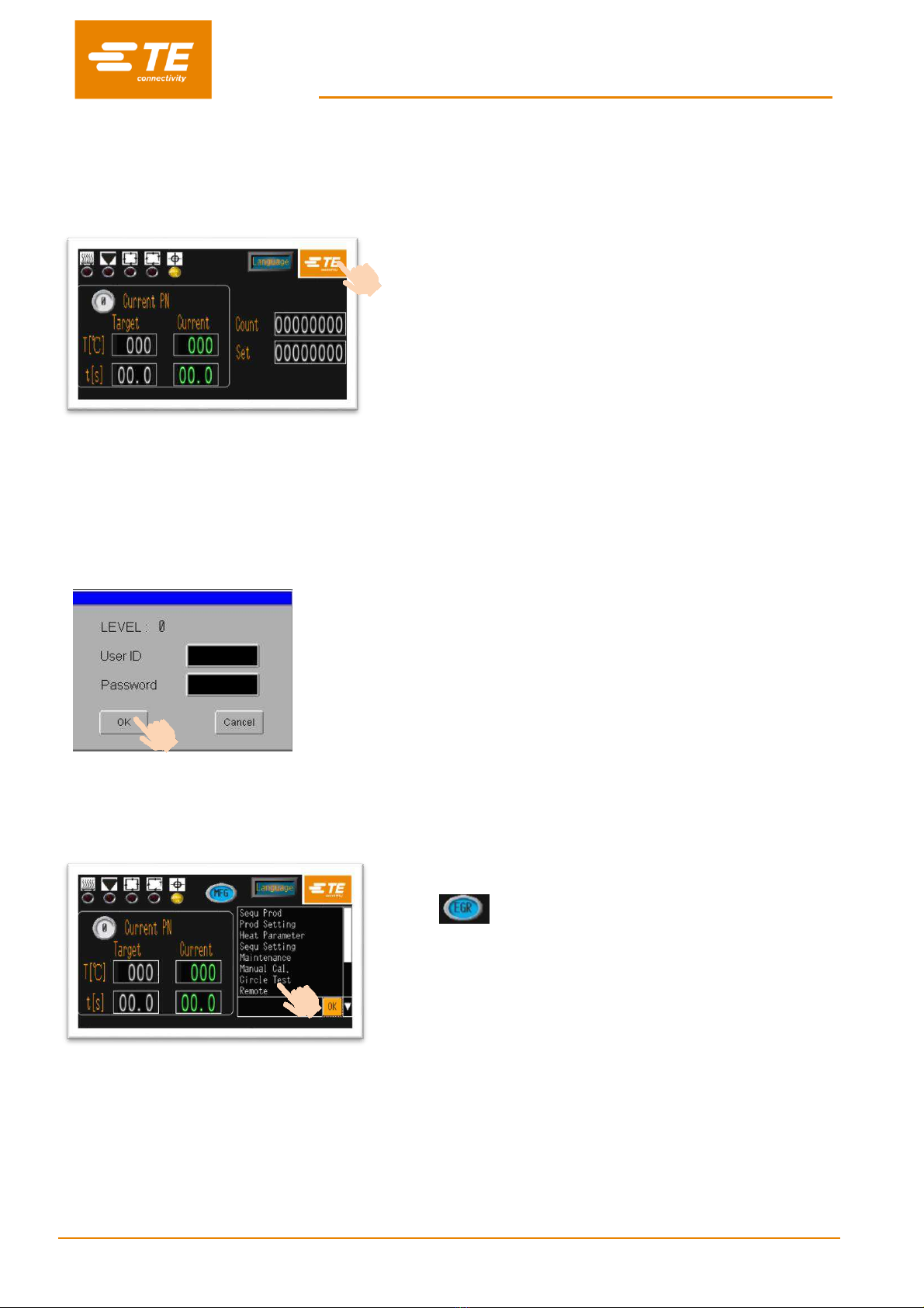
3 Software
The software serves as the processor's central control unit. With this you can set the procedures for product
processing. The software is operated via a touch screen.
When power on to heater, you would see the main
interface like this picture.
Press on the TE logo from the main interface to log on.
3 level authority to log on:
•
“OPR” ---- user ID: “A”, password: “0000”
•
“EGR” ---- user ID: “B”, password: “12345”
•
“MFG” ---- user ID: “C”, (TE kept)
(password can be edit by higher authority.)
Input ID and password in this window.
For example, we are trying to log on as Engineer,
then we should input “B” in user ID column, and input
“12345” in Password column.
Then click on “OK” button.
You would find the main interface already have 2 changes:
•
ID icon is showing you access as engineer.
•
On the bottom right appear a column. Click on it, would
appear a drop-down list.
In this drop-down list, you can choose the setting item,
like show on below table.
12345
B

RBK-X1 / RBK-X1C
Rev. B Jun. 2021
19
Access right for setting item
No log on
OPR
EGR
MFG
Main Interface (Single production)
Sequence production
-
Production setting
-
Auto Cal.
Heat parameter
-
-
Sequence setting
-
-
Maintenance
-
-
Manual Cal.
-
-
Remote
-
Error Log
-
-
System Parameter
-
-
-
Circle Test
-
-
-
I/O & Manual
-
-
-
Centering Manual
-
-
-
Bar code scanning
-
-
This manual suits for next models
5
Table of contents


