DTM System POMENA User manual

PL
DE
EN
LAMPA SYGNALIZACYJNA
Instrukcja obsługi
DIE BLINKLAMPE
Betriebsanleitung
FLASHING LAMP
User’s manual
v.1.1


3
PL
1. PRZEZNACZENIE
Lampy sygnalizacyjne z serii POMENA przeznaczone są dla branży automatyki, wszędzie tam,
gdzie zachodzi potrzeba sygnalizowania światłem ostrzegawczym pracy urządzeń
automatycznych, głównie bram i zapór drogowych. Lampa występuje w wersji POMENA24,
POMENA24B zasilana 24V AC/DC, oraz POMENA230, POMENA230B zasilana 230V AC. Lampy
posiadają wbudowaną dwuzakresową antenę do poprawy zasięgu radiowego. W przypadku
konieczności zwiększenia zasięgu radiowego należy zastosować dodatkową antenę zewnętrzną
montowaną na kompatybilnej do lampy podstawce, dostępną jako opcja u producenta.
2. DANE TECHNICZNE LAMP
zasilanie POMENA230, POMENA230B - 230V AC,
POMENA24 , POMENA24B- 24V AC/DC
moc max 5W
temperatura pracy -20°C do +55°C
technologia LED
żywotność 50 000h
przeznaczenie oświetlenie sygnalizacyjne
tryb pracy ciągła lub impulsowa 0,5s
gabaryty obudowy 110x118x mm(bez uchwytu kątowego)94
sposób montażu bezpośrednio lub za pomocą uchwytu kątowego
klasa szczelności IP 44
waga 180g (z uchwytem 250g)
antena wbudowana, dwuzakresowa: 433MHz / 868MHz
3. UWAGI INSTALACYJNE
Lampa sygnalizacyjna spełnia swoje zadanie tylko wtedy, gdy zamontowana jest w miejscu, z
którego jest dobrze widoczna dla osób znajdujących się w obszarze pracy automatyki.
W lampach serii POMENA B, z przezroczystym kloszem, możliwe jest uzyskanie światła białego
poprzez demontaż z płytki elektroniki wewnętrznego, pomarańczowego klosza (rys. 5. str.9).
4. MONTAŻ LAMPY
Lampę mocuje się standardowo na płaszczyźnie poziomej (rys.6, str.9). Przy zastosowaniu
dostarczonego z lampą uchwytu kątowego, możliwy jest montaż na płaszczyźnie pionowej (rys.7.
str.10).
W lampie POMENA230 i POMENA230B występuje napięcie
niebezpieczne 230VAC. Montaż mechaniczny i elektryczny powinien
być przeprowadzony przez osoby wykwalifikowane, posiadające
odpowiednią wiedzę i narzędzia, zgodnie z zasadami obowiązującymi
w miejscu montażu. Przed rozpoczęciem prac należy upewnić się, czy
napięcie zasilania lampy występujące na wyjściu sterownika
automatyki jest właściwe dla posiadanego modelu lampy. Wszystkie
prace podłączenia lampy do instalacji należy wykonać przy odłączonym
napięciu zasilającym sterownik.

4
PL
5. PODŁĄCZENIE ELEKTRYCZNE LAMPY
Lampa może współpracować z większością central sterujących automatyką bramową
znajdujących się na rynku.
Lampy POMENA230 i POMENA230B należy podłączyć do wyjścia sterownika przeznaczonego
dla lampy sygnalizacyjnej 230VAC. Lampy POMENA24 i POMENA24B należy podłączyć do
wyjścia sygnalizacyjnego o napięciu wyjściowym 24V AC/DC.
Jeżeli urządzenie, do którego podłączona jest lampa nie ma wbudowanego przerywacza, można
uruchomić wbudowany w lampach impulsator, poprzez odpowiednie założenie zworki (rys.3).
6. PODŁĄCZENIE ANTENY
Podłączeń elektrycznych należy dokonać zgodnie z instrukcją urządzenia, do którego będzie
podłączona antena. Do podłączenia anteny użyć kabla koncentrycznego o impedancji 50Ω. Kabel
koncentryczny anteny podłączyć do zacisku oznaczonego symbolem (środkowa żyła kabla) i do
zacisku oznaczonego symbolem (ekran kabla do masy układu). Sposób przygotowania
przewodu antenowego przedstawiono na rys. 4.
TRYB PRACY
CIĄGŁY
TRYB PRACY
IMPULSOWY
zasilanie
0.5 0.5 s.
zasilanie
Rys. 3 Konfiguracja trybu pracy
lamp POMENA.
Rys. 4 Sposób przygotowania
przewodu antenowego.
PRZEWÓD ANTENOWY
6,5mm
3,5mm
Rys. 1 Schemat elektryczny
podłączenia POMENA230
i POMENA230B
do sterownika automatyki.
Rys. 2 Schemat elektryczny
podłączenia POMENA24
i POMENA24B
do sterownika automatyki.
Centrala
sterująca
WY lampy
230V AC
WE
antena
Centrala
sterująca
WY lampy
24V AC/DC
WE
antena

5
DE
1. HAUPTANWENDUNG
Die Signalleuchten der Serie POMENA sind für die Automatisierungsindustrie konzipiert, überall
dort, wo der Betrieb von automatischen Geräten, vor allem von Toren und Schranken, mit einem
Warnlicht signalisiert werden muss. Die Lampe ist in den Versionen POMENA24, POMENA24B
mit 24V AC/DC und POMENA230, POMENA230B mit 230V AC erhältlich. Die Lampen haben eine
eingebaute Dual-Band-Antenne zur Verbesserung der Funkreichweite. Wenn die Funkreichweite
erhöht werden soll, sollte eine zusätzliche externe Antenne auf einem lampentauglichen Sockel,
der als Option beim Hersteller erhältlich ist, verwendet werden.
2. TECHNISCHE DATEN VON LAMPEN
Spannungsversorgung POMENA230, POMENA230B - 230V AC,
POMENA24, POMENA24B - 24V AC/DC
Leistung max 5W
Betriebstemperatur -20°C bis +55°C
Technologie LED
Lebensdauer 50 000h
Anwendung Signalisierung
Betriebsart Constant / Puls 0,5s
Gehäuse 110x118x mm(Ohne Winkelgriff)94
Montage direkt oder mit Hilfe vom Winkelgriff
IP IP 44
Gewicht 180g (mit Winkelgriff 250g)
Antenne eingebaute Zweifrequenzantenne 433MHz/868MHz
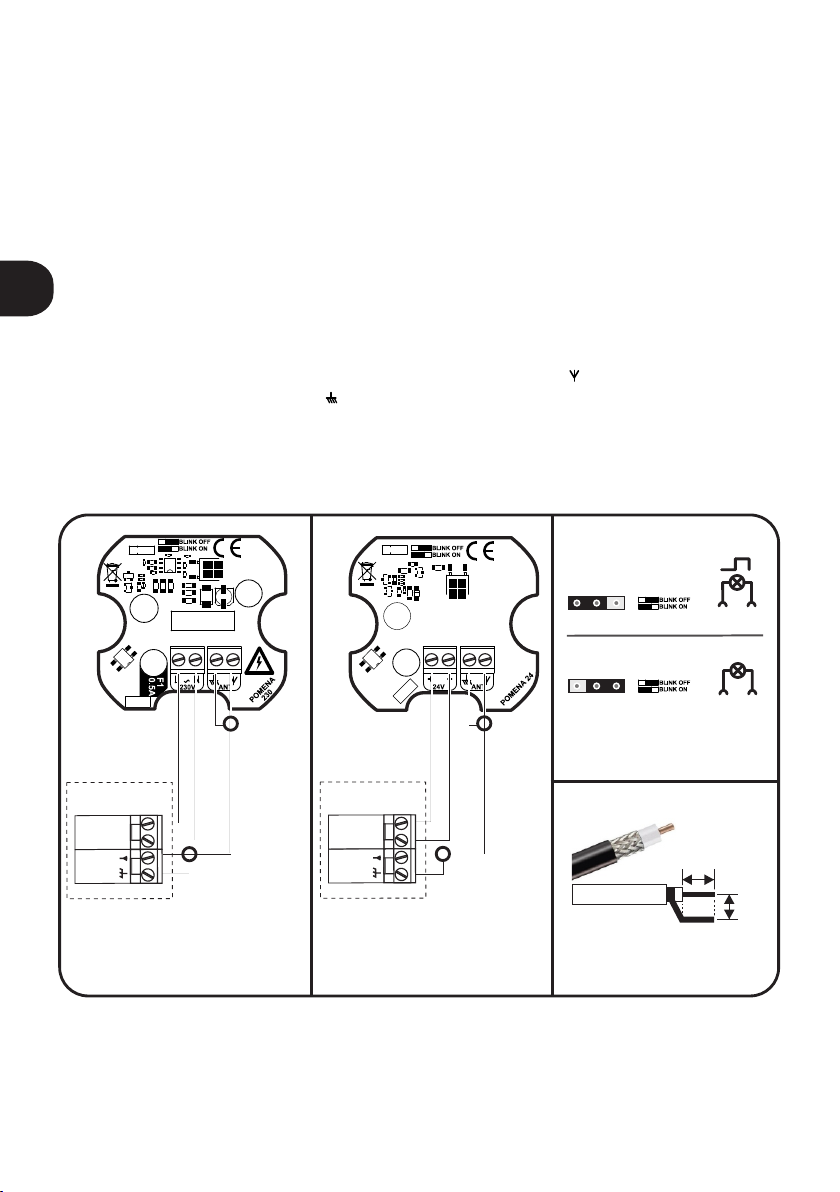
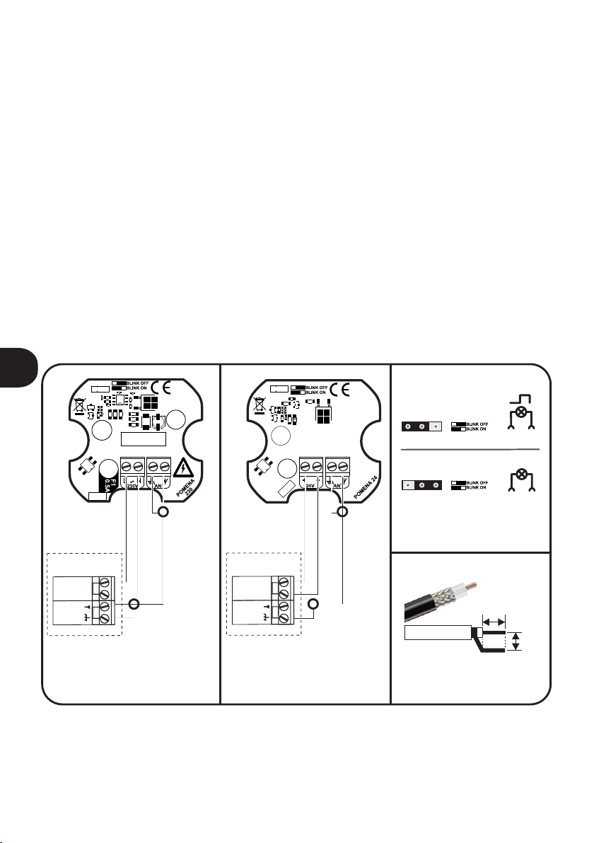
3. MONTAGEANWEISUNG
Die Blinklampe hat eine entsprechende Funktion, wenn man diese Blinklampe an einem gut
sichtbaren Platz für alle Nutzer der Torautomatik installiert.
Bei den Leuchten der Serie POMENA B mit transparentem Lampenschirm kann man weißes Licht
erhalten, indem man es von der internen Elektronikplatine, orange, demontiert. (Abb.5 Seite 9)
4. MONTAGE DER BLINKLAMPE
Die Standardmontage ist eine waagerechte Montage (Abb. 6, S.9). Mit Hilfe vom Winkelgriff (im
Set erhältlich) ist es aber auch möglich eine senkrechte Montage (Abb. 7, S.10).
Lampen POMENA230 und POMENA230B haben eine gefährliche
Spannung von 230VACDie Montage der Antriebsautomatik- und
Elektronik darf nur durch fachgeschultes Personal ausgeführt werden.
Alle Anschlüsse nur beiausgeschaltetem Gerät vornehmen. Die
Blinklampe POMENA230, POMENA230B zählt sich zu der
Gerätekategorie "Tor-und Türautomatik" und erfordert höchste
Sicherheitsvorkehrungen. Die Aufgabe des Monteurs ist es das System
so Betriebssicher zu installieren um jedes Risiko zu verkleinern. Für alle
ewentuell auftretenden Beschädigungen am Gerät, die auf eine
fehlerhafte Installation zurückzuführen sind, haftet der Monteur.

6
DE
5. ELEKTRISCHES ANSCHLUSS-SCHEMA FÜR LAMPEN
Die Lampe kann mit allen üblichen Torsteuerungen auf dem Markt arbeiten.
Die Blinklampe POMENA230, POMENA230B soll man an die entsprechenden Ausgänge der
Steuerungszentrale für 230VAC Lampe anschließen. Die Blinklampe POMENA24, POMENA24B
soll man an die entsprechenden Ausgänge der Steuerungszentrale für 24V AC/DC Lampe
anschließen.
Mit Hilfe vom Jumper in der Blinklampe kann man eine dauerhafte Leuchte oder Blinken einstellen
(Abb. 3).
6. ANSCHLUSS DER ANTENNE
Die Elektroanschlüsse sollen gemäß der Bedienungsanleitung des Gerätes, an das die Antenne
angeschlossen wird, erfolgen. Zum Anschluss der Antenne soll ein konzentrisches Kabel mit dem
Scheinwiderstand von 50Ω genutzt werden. Dieses konzentrische Antennenkabel ist an die
Klemme mit dem Symbol Y (mittlere Kabelader) und an die Klemme mit dem Symbol GND
(Kabelschirm an die Masse des Systems) anzuschließen. Die Vorbereitungsweise des
Antennenkabels zeigt die Abb. 4.
BETRIEBSART: CONSTANT
BETRIEBSART: PULS
Spannungsversorgung
0.5 0.5 s.
Spannungsversorgung
Abb. 3 Einstellung
der Betriebsarten
Abb. 4 Die Vorbereitungsweise
des Antennenkabels
6,5mm
3,5mm
Abb. 1 Anschlussschema
der Blinklampe POMENA230,
POMENA230B
an die entsprechenden Ausgänge
der Steuerungszentrale
Steuerungszentrale
EIN Lampe
230V AC
AUS
Antenne
EIN Lampe
24V AC/DC
AUS
Antenne
Abb. 2 Anschlussschema
der Blinklampe POMENA 24,
POMENA24B
an die entsprechenden Ausgänge
der Steuerungszentrale
Steuerungszentrale
ANTENNENKABEL

7
EN
1. USAGE
POMENA series signal lamps are designed for the automation industry, wherever there is a need
for a warning light signaling the operation of automatic devices, mainly gates and barriers. The
lamp is available in version POMENA24, POMENA24B powered by 24V AC/DC, and POMENA230,
POMENA230B powered by 230V AC. The lamps have a built-in dual-band antenna to improve the
radio range. If it is necessary to increase the radio range, use an additional external antenna
mounted on a lamp-compatible stand, available as an option from the manufacturer.
2. TECHNICAL DATA
power supply POMENA230, POMENA230B - 230V AC,
POMENA24, POMENA24B - 24V AC/DC
power max 5W
operating temperature -20°C to +55°C
technology LED
vitality 50 000h
usage signal light
operating mode constant or impulse 0,5s
housing dimensions 110x118x mm(without the angle bracket)94
montage directly or with the angle bracket
IP IP 44
waga 180g (with the bracket 250g)
antenna built-in dual band: 433MHz and 868MHz
3. INSTALLATION NOTES
Flashing light serves its purpose only if it is installed in a place where it is clearly visible to people in
the automation working area.
In POMENA B series lamps with a transparent shade, it is possible to obtain white light by
removing the internal orange shade from the electronics board (Fig. 5. page 9).
4.LAMP MOUNTING
The lamp is mounted as standard on a horizontal plane (Fig. 6, p.9). Using the supplied bracket,
lamp can be mounted on a vertical plane (Fig. 7, p.10).
230VAC dangerous voltage present in POMENA 230 and POMENA 230B
lamp. Mechanical and electrical installation should be performed by
qualified personnel with adequate knowledge and tools in accordance
with the rules in force at the installation site. Before installing make sure
the supply voltage at the controller output is correct for your lamp
model. All the work of connecting the lamp to the installation should be
performed with the controller power supply disconnected.

8
EN
5. ELECTRICAL CONNECTION
The lamp can operate with most of the gate controllers on the market.
POMENA 230, POMENA 230B must be connected to the controller output designed for 230V lamp.
POMENA 24, POMENA 24B must be connected to the controller output designed for 24V lamp.
If gate controller does not have a built-breaker, it can be run through appropriate setting of the
jumper in the lamp (Fig. 3).
6. ANTENNA CONNECTION
Electrical connections should be made in accordance with the instructions of the device to which
the antenna will be connected. Use 50Ω coaxial cable to connect the antenna. Connect the coaxial
cable to the terminal marked with the symbol Y (center wire) and to the terminal marked GND. The
preparation of the antenna cable is shown in Fig. 4.
CONTINUOUS MODE
PULSE MODE
power
0.5 0.5 s.
power
Fig. 3 Operation mode
configuration.
Fig. 4 Preparation
of the antenna wire.
6,5mm
3,5mm
Fig. 1 Electrical diagram
of POMENA 230, POMENA 230 B
connection to the automation
controller.
gate controller
OUT lamp
230V AC
INPUT
antenna
OUT lamp
24V AC/DC
INPUT
antenna
ANTENNA WIRE
Fig. 2 Electrical diagram
of POMENA 24, POMENA 24 B
connection to the automation
controller.
gate controller

9
EN
DE
PL
Lampensockel auf einer
horizontalen Ebene ohne
zusätzlichen Halter montiert.
Verlegung der Strom-
und Antennenkabel
2
klosz
Rys. 6 Montaż lampy do powierzchni poziomej.
Lampenschirm
lampshade
2x wkręt mocujący
klosz lampy do podstawy
2x Schraube zur
Befestigung der Lichtkuppel
am Sockel.
2x screw fastening
lampshade to the base
podstawa lampy mocowana
na poziomej płaszczyźnie
bez dodatkowego uchwytu
sposób prowadzenia przewodu
zasilającego i antenowego
lamp base mounted
on a horizontal plane
without an additional holder
power supply
and antenna wiring way
Abb. 6 Montage der Lampe auf einer horizontalen Fläche.
Fig. 6 Lamp assembly to a horizontal surface.
Rys. 5 Demontaż klosza wewnętrznego dla uzyskania
emisji światła białego w lampach typu POMENA B.
Abb. 5 Demontage der Innenlinse für die Weißlichtabgabe
bei Lampen des Typs POMENA B.
Fig. 5 Disassembly of the inner lampshade
to obtain white light emission in POMENA B lamps.

10
EN
DE
PL
2x wkręt mocujący lampę
do uchwytu kątowego
lamp base
Verlegung der Strom-
und Antennenkabel
2
klosz
2x Schraube zur
Befestigung der
Lichtkuppel am Sockel.
dodatkowy uchwyt
90° do montażu na
powierzchniach
pionowych
3
Rys. 7 Montaż lampy do powierzchni pionowej za pośrednictwem uchwytu kątowego.
Lampensockel
Lampenschirm
2x wkręt mocujący
klosz lampy
do podstawy
podstawa lamp
2x Schraube zur
Befestigung der Lampe
an der Winkelhalterung
2x screw fastening the
lamp to the angle bracket
Zusätzlicher 90°
– Halter zur Montage an
vertikalen Flächen.
additional 90 ° handle
for mounting on vertical surfaces
sposób prowadzenia
przewodu zasilającego
i antenowego
2x screw fastening
lampshade to the base
lampshade
power supply
and antenna wiring way
Abb. 7 Befestigung der Lampe an eine vertikale Fläche Mit Hilfe eines Befestigungswinkels
Fig. 7 Mounting the lamp to the vertical surface via an angle bracket.

11
EN
DE
PL
POMENA - 1:1
obszar na wyprowadzenie
przewodów
otwór mocujący
fi 4,8mm
57,5 mm
47 mm
otwory mocujące
fi 4,8mm
Rys. 8 Rozstaw otworów mocujących lampę oraz uchwyt w skali 1:1
Platz für Kabelleitung
area for placing the wires
Fig. 8 The template for mounting on a vertical surface.
Loch für Montage
mounting hole
Abb. 8 Abstand der Befestigungslöcher für Lampe und Halterung im Maßstab 1:1
UŻYJ TEGO RYSUNKU JAKO SZABLONU / DIESE ZEICHNUNG ALS VORLAGE VERWENDEN / USE AS A TAMPLATE
Loch für Montage
mounting holes
UCHWYT
WINKELGRIFF
BRACKET
1:1

12
DISPOSAL
Electrical or electronic devices cannot be
removed with everyday waste. The correct
recycling of devices gives the possibility of
keeping natural resources of the Earth for a
longer time and prevents the degradation
of natural environment.
WARRANTY
DTM System provides operational and
ready to use devices and gives 24 months
warranty from the selling date to the end
customer. This time is counted according
to the producer warranty labels or serial
numbers placed on every product. DTM
System obliges itself to repair the device
for free if during the warranty period there
are problems which come because of its
fault. Broken device should be supplied on
customer’s expense to the place of
purchase and enclose clear and brief
description of the breakage. The cost of
mount/dismount is covered by the user.
The warranty does not cover any faults
caused by improper usage, user self
repairs, regulations and adaptations,
lightning strikes, voltages or short circuits
in the electrical grid. Appropriate legal acts
regulate details of the warranty.
ENTSORGUNG
Entsorgung der Elektrogeräte bzw.
Elektronik darf nicht in Rahmen der
Ha ush alt sa bfä l le e r fo lg en . E ine
sachgerechte Entsorgung des Gerätes
m a c h t e s m ö g l i c h , n a t ü r l i c h e
Erdressourcen länger aufrecht zu erhalten
s o w i e d e r U m w e l t z e r s t ö r u n g
vorzubeugen.
GARANTIEBEDINGUNGEN
Der Hersteller DTM System übergibt
funktionsfähige und nutzungsbereite
Geräte. Der Hersteller erteilt eine Garantie
von 24 Monaten nach Einkaufsdatum vom
Endkunden gerechnet. Die Garantiezeit
wird auf Basis von Garantieblomben des
Herstellers, die an jedem Erzeugnis
angebracht werden, festgelegt. Der
Hersteller verpflichtet sich dazu, das Gerät
kostenfrei zu reparieren, wenn in der
Garantiezeit Mängel durch Verschulden
des He r s te l le r s au f tr e t en . Ni c h t
funktionsfähiges Gerät ist auf eigene
Rechnung an die Einkaufsstelle zu liefern.
D e r L i e f e r u n g i s t e i n e k u r z e ,
nachvollziehbare Beschreibung des
Schadens beizufügen. Die Demontage-
und Montagekosten gehen zu Lasten des
Betreibers. Die Garantie gilt nicht für
Batterien in den Handsendern, sämtliche
Schäden, die durch unsachgemäße
Verwendung, selbsttätige Regelungen,
Modifikationen und Reparaturen sowie
Schäden infolge von atmosphärischen
Entladungen, Überspannungen bzw.
Ku rz s chl üs s en d e s S tro mn e tz es
entstanden sind. Detaillierte Bedingungen
für Garantieerteilung werden in den
einschlägigen Rechtsnormen geregelt.
UTYLIZACJA
U r z ą d z e ń e l e k t r y c z n y c h l u b
elektronicznych nie można wyrzucać
razem z odpadami gospodarczymi.
Prawidłowa utylizacja urządzenia daje
możliwość zachowania naturalnych
zasobów Ziemi na dłużej i zapobiega
degradacji środowiska naturalnego.
WARUNKI GWARANCJI
Producent DTM System, przekazuje
urządzenia sprawne i gotowe do użytku.
Producent udziela gwarancji na okres 24
miesięcy od daty zakupu przez klienta
końcowego. Okres gwarancji określany
jest na podstawie plomb gwarancyjnych
producenta, umieszczanych na każdym
wyrobie. Producent zobowiązuje się do
bezpłatnej naprawy urządzenia, jeżeli w
okresie gwarancji wystąpiły wady z winy
producenta. Niesprawne urządzenie
należy dostarczyć na własny koszt do
miejsca zakupu, załączając kopie dowodu
zakupu i krótki, jednoznaczny opis
uszkodzenia. Koszt demontażu i montażu
urządzenia ponosi użytkownik. Gwarancja
nie obejmuje baterii w pilotach, wszelkich
uszkodzeń powstałyc h w wyni k u
n ie pr aw id ło we g o u ży tk ow a n i a ,
samowolnych regulacji, przeróbek i
napraw oraz uszkodzeń powstałych w
wyniku wyładowania atmosferycznego,
przepięcia lub zwarcia sieci zasilającej.
Szc z eg ó ło we w ar u nk i u d zi e la ni a
gwarancji regulują stosowne akty prawne.
D T M S y s t e m
niniejszym oświadcza,
że ur zą dzenie jes t
zgodne z dyrektywą 2014/30/UE,
2014/35/UE. Pełny tekst deklaracji
zgodności UE jest dostępny pod
adresem internetowym.
DTM System erklärt
h i e r m i t , d a s s d i e
Blinklampe mit der
Richtlinie 2014/30/EU, 2014/35/EU
konform ist. Der Volltext der EU-
Konformitätsbestätigung ist unter
unser Website zugänglich.
DTM System hereby
declares that the device
complies with Directive
2014/30/EU, 2014/35/EU. The full
text of the EU Declaration of
Conformity is available at the
Internet address.
DTM System spółka z ograniczoną odpowiedzialnością spółka komandytowa
ul. Brzeska 7, 85-145 Bydgoszcz, Polska, tel. +48 52 340 15 83, www.dtm.pl
Table of contents
Languages:
Popular Outdoor Light manuals by other brands

Inspire
Inspire Lakko Assembly, Use, Maintenance Manual

Belux
Belux LEIA-10 Assembly instructions

Heitronic
Heitronic 35961 Installation and operating instructions

Epstein-Design
Epstein-Design SAHARA COLUMN 80 manual

Dale Tiffany
Dale Tiffany TT12366 Assembly instructions

LIGMAN
LIGMAN LADOR 11 installation manual

RZB
RZB Home + BASIC HB 301 Instruction

Maxim Lighting
Maxim Lighting Carriage manual

BEGA
BEGA 77 089 Installation and technical information

Access Lighting
Access Lighting NAUTICUS 20290LEDDLP quick start guide

Maximus
Maximus SPL08-07A1N4-ORB-K1 instruction manual

Luminar Outdoor
Luminar Outdoor 59268 owner's manual