DTox DTox07 User manual

This manual covers the Dtox Blue-tooth adaptor and Android application
DTox systems and software are under continuous development and as a result any
images and screen grabs may not accurately reflect the current versions of either.
Any clarification re uests or suggestions about this manual can be addressed to
The latest version of this document is always available at
www.4dfx.com.au/DTox
2
The Dtox Blue-tooth system is an experimental system, just like
your free flight model.
Determining the suitability of the system for your particular application
is solely your responsibility, and you take all responsibility for any
outcome in its use.
Nothing is infallible, and the Dtox Blue-tooth system fits into this
category.

GENERAL DESCRIPTION
The Dtox Blue-tooth adaptor is a replacement for the Palm Pilot programming system
for P type timers (and possibly future times). The adaptor plugs into the programming
port of the P type timer and programming of the timer is accomplished via the
Android app, DToxco fig. The app is free and available for download from the
website.
ADAPTOR
Figure I
Charge i dicators: Amber while charging, green when fully charged.
Status I dicators Red when active, green when connected
O /Off: Power switch
WEIGHT: ~30gm
SIZE: 60mm x 35mm x 15mm (Excluding cable)
FEATURES
Each adaptor has a uni ue ID and passkey,. The ID is on the visible label in the form
of “Dtoxnn” and the 4 digit passkey on the underside of the circuit board. These will
be re uired to connect to the Android application.
Charging of the internal battery is via the mini USB connector at the base of the unit.
Any standard charger such as a phone charger, USB port on your computer or power
bank can be used. Do not exceed 6 volts on input. When a charger is attached an
3

Amber LED will glow during charging. When fully charged the green LED will be
illuminated. The unit does not have to be turned on during charging.
When ready to use turn the unit on and the red status LED will begin flashing rapidly.
Once connected to the Android app the green status LED will illuminate and the red
indicator will flash at a much lower fre uency.
OPERATION
Insert mini USB plug of the adaptor into the timer, ensuring it is fully inserted. If
timer is in deep sleep mode or in a timing se uence, press the reset button on the timer
to return it to the idle state. Turn on the adaptor then run the Android app.
The first time you use the adaptor, the Android system will ask for the passkey to
establish a binding with the adaptor. Once the binding is established you should not
have to enter the passkey again.
4

Dtoxcofig Ver 10.45
Dtoxconfig is an Android application the runs on any Android device with a
minimum of Android version 4.2, and can accommodate many screen resolutions.
There are no plans to create an IOS (Apple) version of the app. The only permissions
it re uires are for Blue-tooth connections. There is no data gathering or ads. Currently
you will have to download the app from the website and do a manual install of
the .apk file (ask a nearby teenager if you don’t know how).
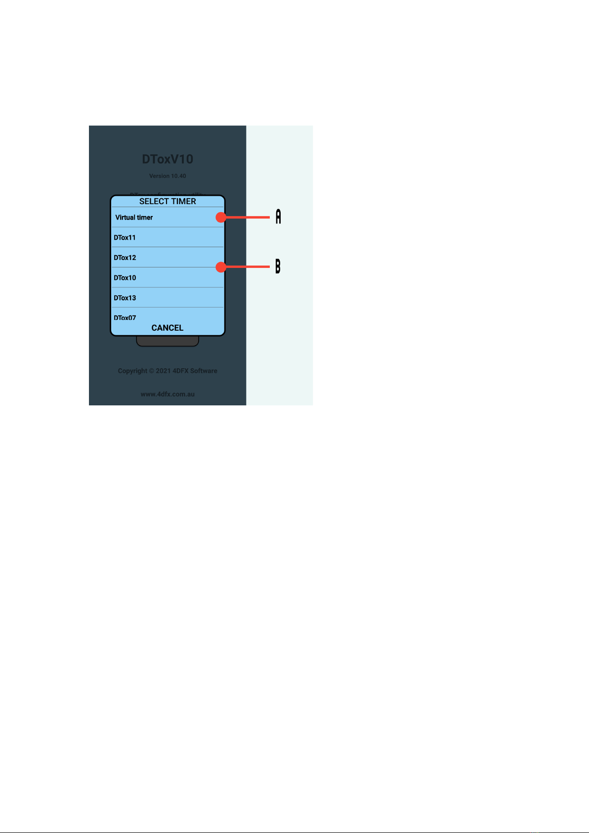
The app is free and has a ‘virtual’ timer inbuilt so you can examine/practice using its
features.
As with all Dtox products, its up to you to determine its suitability for your purposes
and you take all responsibility for any outcomes from its use.
This guide takes you through the app, screen by screen, and explains its functionality.
When using the app, always use the in-app RETURN button to navigate screens,
failure to do this might result in the timer not exiting the programming mode. If this
occurs, the timer will self exit after approximately 5 minute, or if you can’t wait,
pressing the hardware reset button on the timer will bring the timer back to a fresh
idle state (refer to P type timer manual).
The current app, Ver 10.45, only supports P type timers.
Various informative and confirmation pop-up panels may appear during use, they
should all be self explanatory.
5

BEGIN
Find the app on your device and once started you will be presented with this screen
Select option A to see and choose any adaptor(s) previously seen and paired by your
Android device. A list will be presented for you to make a choice.
Select option B to discover any active Blue-tooth devices in range of the Android
device. Only Dtox Bt adaptors will be listed. This search can take some time and
when complete you will presented with a list of adaptors to choose from. You may
also be asked to supply the passkey if the adaptor has not already been paired with
your device.
Option C will reveal a list of all the saved logs on your device.
Always navigate back to this screen when you have finished programming or
examining the timer to ensure timer is ready for action.
6

SAVED LOGS:
File list
All files that have been saved will be listed here. Listed are the file name and
description. (see the file save screen for more details)
To select a file to examine or delete tap on the entry in the list (item A).
Selecting option B will load the file and then enter the flight data screen from which
you can then enter the graphic display.
Selecting option C will, after asking for confirmation, permanently delete the file.
The file cannot be recovered.
7

TIMER SELECTION:
Choose adaptor/timer
Selecting option A will access the inbuilt virtual timer and allow you to examine the
features of the app. No Blue-tooth connection is re uired and the virtual timer is reset
when you exit the programming mode. You will be presented with a choice of timer
to use.
Selecting option B (any timer other than the virtual timer) will cause the app to try
and connect with the adaptor and if successful advance to the programming options
screen
8

Virtual timer choice
Selection is by tapping either the image or the button. All functions are available for
the virtual timer as are for the real one. Once selected you will be presented with the
programming options screen.
Currently there is only one choice for a virtual timer.
9

Programmi g optio s
Selecting option A will present the flight log of the attached timer. (see page 19)
Option B will present the Status screen and provide access to the programming
functions. All subse uent configuration screens have a READ and RETURN button.
The READ button will refresh the data on screen by reading the timer. If there is
unsaved edited data you will be given a warning and an option to cancel the read.
The RETURN button always returns to the previous screen, use this rather than the
system ‘back’ button. As with the READ button, if there is unsaved edited data you
will be prompted to cancel the return.
All screens that allow editing also have an UPDATE button. Selecting this option will
immediately update the timer with the data on the screen. You must use the UPDATE
button to write any changes to the timer.
The RETURN button, option C, will reset the timer and disconnect from the adaptor
(close the blue-tooth connection) then return to the starting screen. This is the proper
way to exit the application.
Option ‘D’ proceeds to a terminal window where direct interaction with the timer is
possible. This feature does not appear for virtual timers.
10

CONFIGURATION:
Status
This screen displays the main current settings of the timer. No changes can be made
here, if you wish to edit any settings select option A, the EDIT button, to proceed to
the main edit screen.
The Read button, on this and subse uent screens will refresh the display by reading
the timer.
11

Mai Edit
Selecting option A, the MENU button, will reveal other edit options in a sub menu.
Changing the times of arm release is accomplished in the ‘a’ section.
You can alter either the Time or the Increment and all subse uent times will be
adjusted accordingly. If the D/T Lock box is checked, indicated by both the checkbox
and time highlighted in red, the final time (release of last arm) will be preserved in
any calculation. If inconstant times result from any change, a warning message will be
displayed and update of the timer will be prevented until the inconstancy is resolved.
Section ‘c’ is used to activate or deactivate various functions.
If RDT is deactivated the timer will not respond to any attached RDT unit. This can
be left activated even if no RDT unit is present.
The altimeter flags are described in detail on the altimeter edit page which is accesses
via the MENU button.
The timer can be configured for 5 arms and a second servo/ESC. See the Hardware
edit screen for details
12

Sub me u selectio
These buttons provide access to less fre uently used configuration edits.
Option A takes you to the altimeter edit, B to the servo position edit and C to the
hardware edit.
To cancel the selection option, tap anywhere on the screen.
13

Altimeter edit
Section ‘a’ is the main altimeter flag, use this to enable or disable the altimeter.
If any of the altimeter functions are disabled, the parameter panel will be hidden.
Section ‘b’ is the recording function. The minimum flight time can be set such that
any flights less than the set amount will not be recorded. Recording will cease after
the D/T time is reached plus an additional time as specified in Max Time. Recording
will actually continue as long as the model is more than 20 meters above ground.
Sampling rates can also be set, this is the sampling rate. The sampling rate is changed
at the time the nominated arm is released.
Section ‘c’ sets the absolute altitude limit. If the set altitude is exceeded the timer will
advance directly to the D/T position.
Section ‘d’ controls the fail-safe mode. If the timer is in the idle state and detects a
change in altitude of the specified amount within the specified time the cam servo will
be moved to release the D/T line
Section ‘e’ is an experimental feature, play with at your own risk. It is designed to
minimise total flight time by calculating decent time and D/Ting early if possible.
14

Servo edit
This warning message is displayed to make sure you realise the possibilities of
activating the power switch if there is an ESC attached to the timer as the second
servo. If the system is ready and power applied, selecting the second (ESC) servo
could result in motor start and a lot of damage and heartache…… be aware!
Note also that if an ESC is connected to the timer, it will have its own power supply
and using the power button on the edit screen will only turn off the control signal, not
its power.
To continue to the servo edit tap the button.
15

Servo edit
The P type timer basically moves the cam servo to a predetermined positions at the
programmed time. Adjustments should not be re uired as the timers are setup before
delivery. Here is where you set the position of the servo if adjustments are re uired.
If an ESC is attached to the timer you can also set the control pulse width at indicated
times. If power is switched on, certain options are disabled until its switched off.
During adjustment, if the power is switched on, the servo/ESC will track the value set
by the slider.
Power is turned off or on by tapping the button ‘a’.
Selection of servo or second servo/ESC is by button ‘b’.
Selection of time position is by one of the group ‘c’ buttons.
The value of the servo rotation is set by the slider ‘d’. Trim adjustments, of 10 units
up or down can be done by tapping the appropriate arrow button ‘e’. Values represent
pulse width sent to servo, 1000 = 1ms.
Servo positions are: Park: position when timer is idle
Ready: when timer is armed and ready to release Arm#1
Arm#1: Arm#1 released, ready to release ARM#2
Arm#2: Arm#2 released, ready to release ARM#3
Arm#3: Arm#3 released, ready to release ARM#4
Arm#4: Arm#4 released, ready to release ARM#5
Arm#5: Arm#5 released, cam fully open
Note that 5 arms are shown here, this is selected via the Hardware edit screen, as is
the presence of the second servo/ESC.
16

Hardware edit
Only the items indicated can be edited/changed, the rest is just FYI.
The text displayed for the arm positions can be edited at group ‘a’. Text is limited to
10 characters per item.
Selecting item ‘b’, TP5, will include a fifth servo position labelled Arm#5, to the
timing to the timing and servo edit screens. You could add a physical arm to the timer,
but you’re on your own for that. More probably you might want an extra position for
the servo cam or second servo/ESC.
Item ‘c’ will reverse the sense of the two buttons on the timer. The reset button will
become the trigger button and vice-versa.
The ESC/Servo0 flag will activate and expose configuration areas in the servo and
timing screens for the second servo/ESC. See the next section on Extended edit
screens.
17

Exte ded edit scree s
The above diagram illustrates the edit screen when both the 5th arm and ESC/Servo0
flags are activated.
The times in the ESC group,‘D’, are edited in the same manner as the Arm Release
group. Either the Time or Increment can be changed and all subse uent entries will be
modified automatically.
Tapping the Sync Time button, ‘e’, will copy the times from the Arm Release group
to the ESC group.
18

TERMINAL WINDOW:
The terminal window is used to directly communicate with the timer and is primarily
used for debugging purposes.
Commands are entered at ‘B’ and the timer response is displayed in area ‘A’
Users are not encouraged to play here, but if you must, try entering ‘d’. This will
display the contents of the configuration EEPROM. You can also test the altimeter by
entering ‘p’. This will result in a continuous stream of altimeter readings. The only
way to stop this stream is to press the left button on the timer.
19

TIMER LOGS:
Flight Log scree
A list of the flight logs is presented. An indication of how many flights the timer has
ever recorded, and the number currently stored is displayed at the head of the list. The
list contains all the flights currently stored on the timer. The Load (option C) button is
inactive until an item in the list is selected.
Each entry lists the number of records in the flight, the base altitude (altitude of the
timer before launch) and the maximum altitude reached during the flight. The list can
be scrolled if it contains more entries than can be displayed on the screen (item ‘B’).
Initially these altitude figures are relative to the base altitude. If you wish to view the
actual altitude as stored by the timer check the Abs Alt box (item ‘A’).
To view the details of any particular flight, select the entry (item B) and tap the now
activated Load button which will take you to the flight data screen.
The Manage button (option D) will give you the option of deleting the selected log
from the timer, or deleting all the logs. If there are many entries in the log it may take
some time to perform the delete, patience is re uired. Once deleted, logs cannot be
recovered.
20
Table of contents