DualLite LSN Manual

Installation Instructions
and
User Manual
For
Inverter
Power
Systems
1.0 - 17.5 KVA

2
READ AND FOLLOW ALL SAFETY
INSTRUCTIONS
IMPORTANT SAFEGUARDS
When using electrical equipment, you should always follow basic safety precautions,
including the following:
1. Read and follow all safety instructions.
2. Do not install the LSN (Life Safety Network) inverter system outdoors.
3. Do not install near gas or electric heaters or in other high-temperature locations.
4. Use caution when servicing batteries. Battery acid can cause burns to skin and
eyes. If acid is spilled on skin or in the eyes, ush with fresh water and contact a
physician immediately.
5. Equipment should be mounted in locations where it will not be readily subjected to
tampering by unauthorized personnel.
6. The use of accessory equipment not recommended by the manufacturer may
cause an unsafe condition and may void the warranty.
7. Do not use this equipment for other than intended use.
8. All servicing of this equipment must be performed by qualied service personnel.
SAVE THESE INSTRUCTIONS
IMPORTANT SAFETY INSTRUCTIONS
The installation and use of this product must comply with all national, federal, state,
municipal, or local codes that apply.
Please read this manual thoroughly before operating the LSN Inverter System.
For technical assistance, contact Dual-Lite’s Systems Technical Support
Center at 1-800-848-6439.
Technicians are available during normal working hours (EST).

3
Table of Contents
Section 100 System Installation Instructions
Description Page
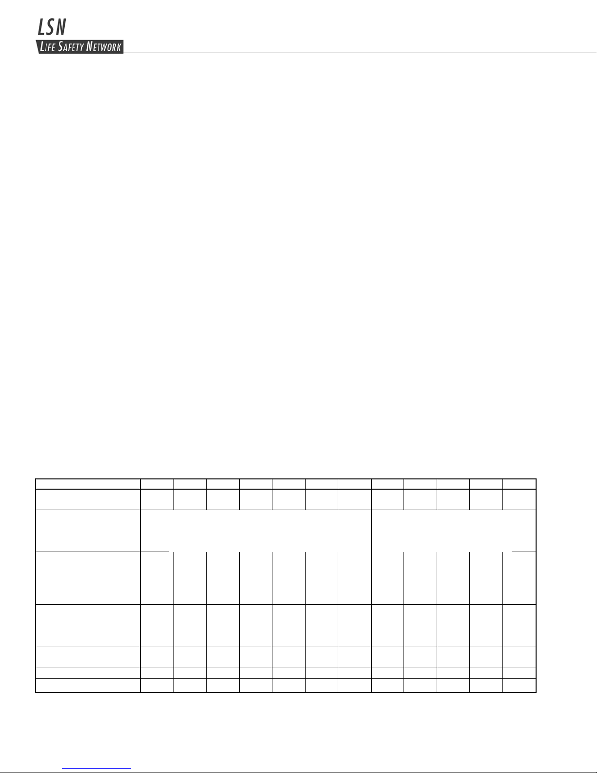
101. UnitSpecications ........................................................................................................................................................... 4
102. Receiving, Moving and Storing Systems and Batteries ............................................................................................... 5
102.1 Shipping Damage................................................................................................................................................................ 5
102.2 Moving Units and Batteries ................................................................................................................................................. 5
102.3 Temporary Storage of Units and Batteries .......................................................................................................................... 5
103. Installation Requirements................................................................................................................................................ 6
103.1 Operating Environment ....................................................................................................................................................... 6
103.2 High Altitude Operation ....................................................................................................................................................... 6
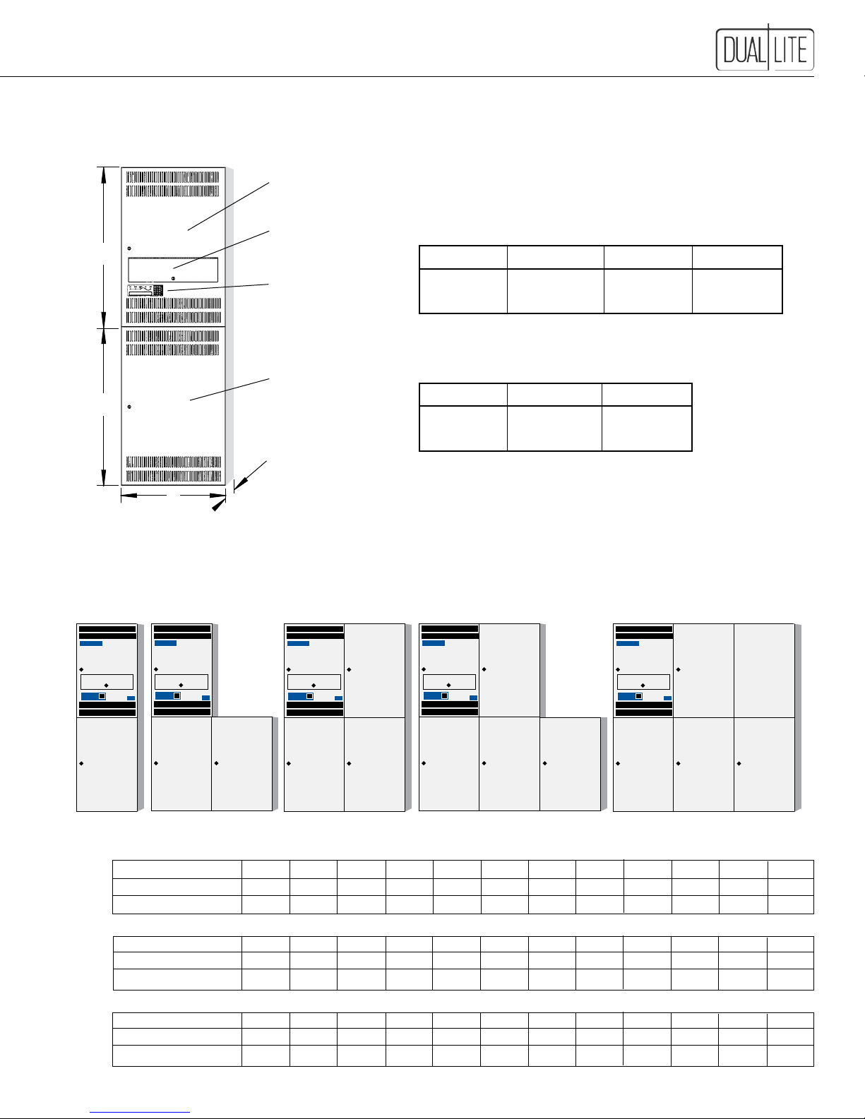
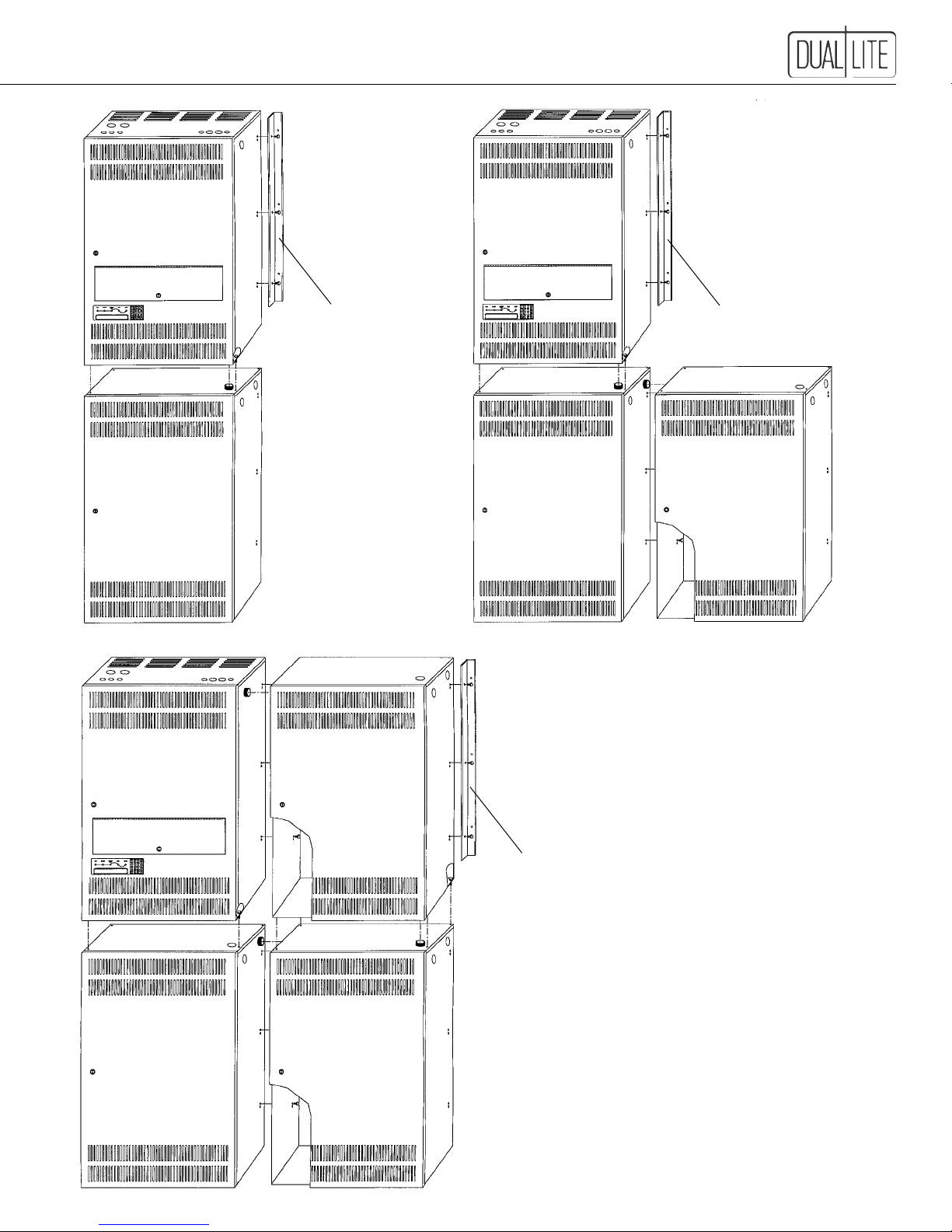
104. Cabinet Mounting (Physical) ........................................................................................................................................... 7
104.1 Dimensions ......................................................................................................................................................................... 7
104.2StandardCabinetCongurations........................................................................................................................................ 7
104.3 Cabinet Installation........................................................................................................................................................... 8,9
105. Battery Installation and Connection............................................................................................................................. 10
105.1 Tools...................................................................................................................................................................................11
105.2 Installation Considerations ................................................................................................................................................ 12
105.3 Battery Installation Procedure...................................................................................................................................... 12-16
105.4 DC Fuse Installation.......................................................................................................................................................... 17
105.5 Electronics Cabinet Voltage Check................................................................................................................................... 17
106. AC Connections.............................................................................................................................................................. 18
106.1 AC Wiring Preparations..................................................................................................................................................... 18
106.2 AC Input and AC Output Connections............................................................................................................................... 19
107. RS-232 Communications Connections ........................................................................................................................ 20
108. Final Installation Checklist ............................................................................................................................................ 20
109. Maintenance Bypass Switch Phase Check.................................................................................................................. 21
110. System Start-Up Procedure........................................................................................................................................... 22
111. SystemVerication ........................................................................................................................................................ 22
Section 200 User Manual
Description ...........................................................................................................................................................................Page
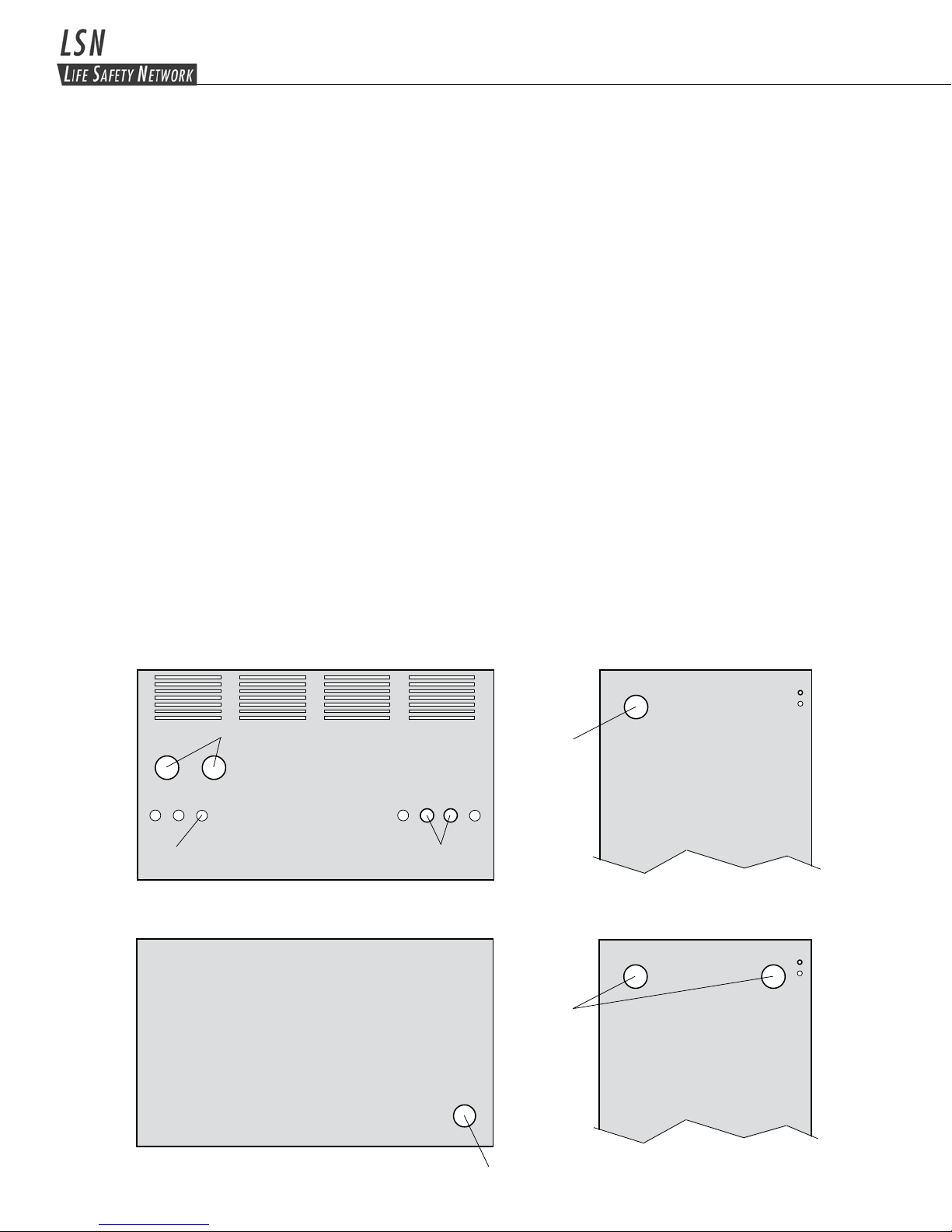
201. User Interface Panel....................................................................................................................................................... 23
201.1 User interface Panel Basics.............................................................................................................................................. 23
201.2 Using The Interface Panel................................................................................................................................................. 24
201.3 How To Display A Parameter............................................................................................................................................. 24
201.4 How to Clear A User Password ......................................................................................................................................... 24
201.5 How o Change A Parameter Value.................................................................................................................................... 24
201.6 How to Change Operating Modes..................................................................................................................................... 25
201.7 Parameter "Hot Key" Listing By Function..................................................................................................................... 26,27
202. System Diagnostics ....................................................................................................................................................... 28
203. System Auto Testing ...................................................................................................................................................... 28
203.1 Weekly Test....................................................................................................................................................................... 28
203.2 Monthly Test ...................................................................................................................................................................... 28
203.3 Annual Test........................................................................................................................................................................ 28
203.4 Extended Power Outages ................................................................................................................................................. 28
203.5 Performing A Manual Test ................................................................................................................................................. 29
204. Stored Test Results (Logs)............................................................................................................................................ 29
205. Alarms ............................................................................................................................................................................. 31
206. Communications ............................................................................................................................................................ 33
207. Unit Communication Options........................................................................................................................................ 33
208. Service Options .............................................................................................................................................................. 34
Section 300 Maintenance, Warranty and Technical Support
300. Maintenance.................................................................................................................................................................... 35
300.1 Safe Shut Down Procedure............................................................................................................................................... 35
300.2 Routine System Maintenance ........................................................................................................................................... 36
300.3 Changing Air Filters........................................................................................................................................................... 36
300.4 Battery Maintenance and Replacement....................................................................................................................... 37-39
301. Warranty Information ..................................................................................................................................................... 39
302. Technical Service and Support ..................................................................................................................................... 39
Appendix 1 ...................................................................................................................................................................... 40

4
Section 100 System Installation Instructions
101Specications
Input
• Inputvoltage:120,208,240,277or347VAC+10-15%.Othervoltagesavailableonrequest
• Inputfrequency:60Hz±3%
• Synchronizingslewrate:1Hzpersecondnominal
• Inputlightningprotection:MeetsANSI62.41,UL924andUL1778requirements
Output
• Outputvoltage:120,240,277,240/120,277/120or347VAC.Othervoltagesavailableuponrequest
• Outputregulation:(static)±5%basedona5%-100%resistiveload
• Minimumloading:nonerequired
• Outputdistortion:Lessthan5%THDlinearload
• Loadpowerfactor:.75lagto.8lead
• Outputfrequency:Normally,synchronizedtoutility,
+.05Hzduringemergency
• Overload:150%momentary,120%forveminutes,
110%fortenminutes
• Timetotransfertoinverterafterautilitypowerfailure:Nobreak
Battery
• Batterycharger:Fullyautomaticandtemperaturecompensatedwithinternaldiagnosticindicators
• Rechargetime:24hours
• Batteryprotection:Automaticlow-batteryvoltagedisconnect.
Automatic restart upon utility return
• Batteryswitch:Alsousedasbatteryisolator
• Standardbattery:"S"-Sealedlead-calcium:10-yearlife
• Optionalbatteries:
"G"-Sealedlead-calcium:20-yearlife
"N"-Wetnickel-cadmium:25-yearlife
• Batteryvoltage:96VDCor144VDC(systemdependent)
• Runtimes:90minutesstandard.Otherruntimesavailableonrequest
• Operatingtemperature:0°Cto40°C(32°Fto104°F)
• Relativehumidity:95%non-condensing
Note:Batteryperformanceratedat25°C(77°F)
Table 1.
KVA/KW Rating 1.0K 2.0K 2.7K 3.7K 4.8K 5.5K 6.6K 8.3K 10.0K 12.5K 15.0K 17.5K
Power Factor Rating .8 lead to .8 lead to .8 lead to .8 lead to .8 lead to .8 lead to .8 lead to .8 lead to .8 lead to .8 lead to .8 lead to .8 lead to
.75 lag .75 lag .75 lag .75 lag .75 lag .75 lag .75 lag .75 lag .75 lag .75 lag .75 lag .75 lag
Input/Output
Voltage Combinations
Available — Single Phase
AC Input Voltage/ 120/20A 120/30A 120/40A 120/50A 120/70A 120/70A 120/80A — — — — —
Input Circuit Breaker 208/15A 208/20A 208/25A 208/30A 208/40A 208/40A 208/50A 208/70A 208/80A 208/100A 208/125A —
Rating 240/15A 240/15A 240/20A 240/25A 240/35A 240/35A 240/45A 240/60A 240/70A 240/80A 240/100A —
277/15A 277/15A 277/20A 277/25A 277/30A 277/30A 277/40A 277/50A 277/60A 277/70A 277/90A 277/100A
347/15A 347/15A 347/20A 347/20A 347/25A 347/25A 347/30A 347/50A 347/50A 347/60A 347/80A 347/80A
Output Voltage and 120/8.3 120/16.6 120/22.5 120/30.8 120/40.0 120/45.8 120/55.0 120/69.1 120/83.3 120/104.1 120/125 120/146
Maximum Output Current 240/4.2 240/8.3 240/11.3 240/15.4 240/20.0 240/22.9 240/27.5 240/34.6 240/41.7 240/52.1 240/62.5 240/72.9
In Amperes 277/3.6 277/7.2 277/9.7 277/13.4 277/17.3 277/19.9 277/23.8 277/29.9 277/36.1 277/45.1 277/54.2 277/63.2
347/2.9 347/5.8 347/7.8 347/10.7 347/13.4 347/15.9 347/19.0 347/23.9 347/28.8 347/36.0 347/43.2 347/50.4
Standard Charger Size 5 5 5 5 10 10 10 10 10 15 15 15
(Amperes)
System DC Voltage 96 96 96 96 96 96 96 144 144 144 144 144
Heat Output (BTU/Hr.) 175 350 473 648 840 963 1,155 1,453 1,750 2,188 2,625 3,063
(1) On systems with 120/240VAC output, loading may not exceed 50% of the system's total KVA rating on any 120V leg. Loading beyond 50% on
any 120V leg will cause an unsafe condition and transformer failure will occur. Call our Service Line at 800-848-6439 for alternate load connection
congurations.
(2) Anexternaltransformermayberequiredwithcertaininput/outputvoltagecongurations.Consultfactoryfordetails.
(3) Input voltage on 17.5KVA model limited to 277 and 347VAC only.
InputVAC:120,208,240,277,347
OutputVAC:120,240,277,347,120/240(1),120/277
Other voltages available; consult factory (2)
InputVAC:208,240,277,347 (3)
OutputVAC:120,240,277,347,
120/240(1),120/277
Other voltages available; consult factory (2)

5
102. Receiving, Moving and Storing Systems and Batteries
102.1 Shipping Damage
LSN inverter systems and batteries are normally shipped separately.
Carefully inspect all cartons upon receipt for evidence of shipping damage.
Notify carrier immediately of leaking or damaged cartons for possible concealed damage.
All LSN electronics cabinet cartons are shipped with tip and vibration indicators.
Refuse all shipments in which the tip or vibration indicators have been activated.
102.2 Moving Units and Batteries
CAUTION: Batteries and LSN Electronics cabinets are very heavy. Proper equipment should
always be used to move batteries and units to avoid damage and personal injury.
WARNINGS:
• ALWAYS WEAR PERSONAL EYE PROTECTION WHEN WORKING WITH BATTERIES - SEE PAGE 10
• Batteries contain liquid caustic or acid electrolytes which CAN CAUSE SEVERE BURNS.
Care must be taken when moving batteries to avoid tipping and spillage of electrolyte material.
In case of accidental spill.
ANTIDOTE:
• EYES: Flush immediately with owing water for at least 15 minutes. Seek medical attention.
• EXTERNAL: Flush immediately with water. Seek medical attention.
102.3 Temporary Storage of Units and Batteries
For temporary storage of LSN inverter systems and batteries prior to installation, select a clean, cool, dry location with
normalventilationforhumanhabitationandleveloors.
CAUTION: Batteries and LSN Electronics cabinets are very heavy. Check to assure that the oor in the
temporary storage area is capable of safely bearing the load.
IMPORTANT:
Lengthy storage of batteries will cause irreversible damage to the cells.
Failure to connect LSN inverter system batteries to an energized charging circuit within 90 days from the date
of shipment will void the battery warranty.
Storage Temperature:
Storeallbatteriesat0°to+40°C(32°to+104°F).Batterieswillhavealongershelflifeifstoredat25°C(77°F).
TheLSNelectronicsandbatterycabinetsmaybestoredat-20°to+60°C(-4°to+140°F).
Ventilation:
The air around the unit must be clean, dust-free, and free of corrosive chemicals or other contaminants. Do not place
the LSN inverter system or batteries in a sealed room or container.
DANGER: EXPLOSIVE - CAN CAUSE BLINDNESS OR OTHER SEVERE INJURIES.
Every type of battery can produce hydrogen gas, even sealed, maintenance-free batteries. The gas is vented through
the vent caps and into the air.
Do not allow smoking, sparks, or ames in battery storage location because hydrogen is concentrated under
the vent cap of each cell of the battery. Hydrogen is highly explosive, and is hard to detect because it is
colorless, odorless, and lighter than air.

6
103. Installation Requirements
103.1 Operating Environment
InstalltheLSNinvertersysteminaclean,cool,dryplacewithnormalventilationforhumanhabitationandleveloors.
CAUTION: Batteries and LSN Electronics cabinets are very heavy. Check to assure that the
oor is capable of safely bearing the load.
Operating Temperature:
LSN inverter Systems are UL Listed for 20° to 30° C (+ 68° to +86° F) operation.
TheLSNInverterSystemhasadesignedoperatingrangeof0°to+40°C(+32°to+104°F)atupto95%relative
humidity. Installation in environments at the temperature extremes of the designed operating range may effect unit
performance or reduce service life.
Battery performance and service life is maximized if the operating temperature is maintained at 25° C (77° F) .
Ventilation:
The air around the unit must be clean, dust-free, and free of corrosive chemicals or other contaminants. Do not place
the LSN inverter system or batteries in a sealed room or container.
Batteries:
Thetemperatureshouldbenear25°C(77°F)foroptimumbatteryperformance.
Temperature Effect On Performance:
Batterieswillbelessefcientattemperaturesbelow18°C(65°F),andhightemperatureswillreducebatterylife.
Typically,at35°C(95°F),batterylifewillbehalfofwhatitwouldbeatnormaltemperatureof25°C(77°F).At45°C
(113°F),batterylifewillbeone-fourthofnormal.
WARNING: Every type of battery can produce hydrogen gas, even sealed, maintenance-free batteries. The gas is
vented through the vent caps and into the air, mainly when the unit is charging the batteries. The batteries produce the
most hydrogen when maximum voltage is present in fully charged batteries. The amount of current that the charger
suppliestothebatteries(notthebatteryampere-hour)determineshowmuchhydrogenisproduced.
Do not allow smoking, sparks, or ames in battery storage location because hydrogen is concentrated under
the vent cap of each cell of the battery. Hydrogen is highly explosive, and is hard to detect because it is
colorless, odorless, and lighter than air.
IMPORTANT:
Lengthy storage of batteries will cause irreversible damage to the cells.
Failure to connect LSN inverter system batteries to an energized charging circuit within 90
days from the date of shipment will void the battery warranty.
103.2 High Altitude Operation:
Themaximumoperatingtemperaturedrops1°Celsiusper300meters(2°Fper1000feet)abovesealevel.Maximum
elevationis3000meters(10,000feet).
CAUTION
NEVER INSTALL BATTERIES IN A
SEALED ROOM OR ENCLOSURE
!

7
104. Cabinet Mounting
104.1 Dimensions
Table 104A - Dimensions: Unit and Battery Cabinets
Width (A) Height (B) Depth (C) Footprint
30 in. 46 in. 18.65 in 3.88 Ft2
(76cm) (117cm) (47cm) (.36m2)
Table 104B - Clearances Required:
Sides Top Front
0 in. 12 in. 30 in.
(0mm) (31cm) (76cm)
104.2 StandardCabinetCongurations
Conguration
"A"
Conguration
"B"
Conguration
"C"
IMPORTANT: If cabinets are installed in congurations other than those shown, factory
supplied inter-cabinet connectors and battery cables may not t.
B
B
A
C
Electronics
Cabinet
User
Interface Panel
Battery
Cabinet
Circuit Breaker
Access Door
Conguration
"D"
Conguration
"E"
Standard Battery Systems for 90-Minute Runtime
Type S Battery – Maintenance-Free Sealed Lead-Calcium – 10-Year Design Life Expectancy
System Capacity 1.0K 2.0K 2.7K 3.7K 4.8K 5.5K 6.6K 8.3K 10.0K 12.5K 15.0K 17.5K
SystemConguration A A A A A B B B B B C C
TotalWeight(lbs.)* 838 1,116 1,122 1,222 1,492 1,926 2,130 2,475 2,829 2,861 4,121 4,393
Type G Battery – Maintenance-Free Sealed Lead-Calcium – 20-Year Design Life Expectancy
System Capacity 1.0K 2.0K 2.7K 3.7K 4.8K 5.5K 6.6K 8.3K 10.0K 12.5K 15.0K 17.5K
SystemConguration A A A A B B B B B D D D
TotalWeight(lbs.)* 1,365 1,384 1,390 1,472 1,684 2,062 2,630 2,679 3,589 3,657 4,885 5,491
Type N Battery – Wet-Cell Nickel-Cadmium – 25-Year Design Life Expectancy
System Capacity 1.0K 2.0K 2.7K 3.7K 4.8K 5.5K 6.6K 8.3K 10.0K 12.5K 15.0K 17.5K
SystemConguration B B B B B C C D D E E Consult
TotalWeight(lbs.)* 1,075 1,486 1,644 1,894 2,232 2,532 2,812 3,481 3,940 4,720 5,505 Factory
* Approximate system weights

8
Fig. 1 Fig. 2
Fig. 3 Fig. 4
104.3 Cabinet Installation
Basedonthedesiredcabinetcongurationfortheapplication,removetheappropriateknockoutsintheelectronics
and battery cabinets. See Figures 1, 2, 3, or 4 for the knockout locations.
Follow the generalsequencebelowtoinstallthecabinets.
CAUTION: Batteries and LSN Electronics cabinets are very heavy. Check to assure that the oor in the
installation area is capable of safely bearing the load.
1. Locateallmountinghardwareandchase/closenipplesintheaccessoryboxlocatedinsidethebatterycabinet.
2. Arrangethelowercabinet(s)intheirpermanentlocation.Ifmorethanonecabinetistobelocatedonthelower
level(CongurationBorC),fastenthemtogetherusingthesupplied5/16-18x3/4"bolts.Locatethethree
mounting holes in the rear of the battery cabinet and use three bolts per cabinet to secure together. Install the
supplied chase nipple and plastic bushing in the knockouts to connect the lower cabinets together.
3. Securethesuppliedwallmountingbracketstotheelectronicscabinet(CongurationsAandB),ortothe
outermostsidesoftheuppercabinets(CongurationC).Usethreesupplied5/16-18x3/4"boltsperwallbracket.
Note: Only two wall mounting brackets are supplied with the system, normally intended to secure the upper
cabinets to the wall. Consult the factory if additional brackets are needed to secure the lower cabinets to the wall.
4. Placetheuppercabinetsinpositionandsecurethemtogetherusingthesupplied5/16-18x3/4"bolts.Locatethe
three mounting holes in the rear of the battery cabinet and use three bolts per cabinet to secure together.
5. Securetheuppercabinetstothelowercabinetsusingthesupplied5/16-18x11/2"bolts.Installfromtheoorof
the upper cabinets into the top of the lower cabinets. Install the supplied close nipple and plastic bushing in the
knockouts to connect the upper cabinets to the lower cabinets.
6. Securethewallmountingbracketstothewallusinganacceptablewallanchoringtechnique.
BATTERY SIDE
1.951 Diam.
Knockout
Typ. Both Sides
BATTERY SIDE
1.951 Diam.
Knockouts
Typ. Both Sides
1.951 Diam.
Knockout
BATTERY TOP
BATTERY BASE
INVERTER BASE
INVERTER TOP1.125 Diam.
Knockout
Typ. (2)
1.951 Diam.
Knockout
Typ. (2)
0.875 Diam.
Knockout
Typ. (5)
INVERTER SIDE

9
Install Wall
Mounting Brackets
To Top Cabinet On
Both Sides
Conguration“A”
Two
Cabinet Systems
Install Wall
Mounting Brackets
To Top Cabinet On
Both Sides
Conguration“B”
Three
Cabinet Systems
Install Wall Mounting
Brackets To Outermost
Surfaces Of Upper
Cabinets
Conguration“C”
Four
Cabinet Systems

10
105. Battery Installation and Connection
Installing the Batteries and DC Wiring
Important Safety Precautions
Theinstallermusttaketheseprecautions:
1. Wear protective clothing, eye-wear, rubber gloves and boots. Batteries contain corrosive acids or
caustic alkalis and toxic materials and can rupture or leak if mistreated. Remove rings and metal
wristwatches or other metal objects and jewelry. Don’t carry metal objects in pockets where the
objects can fall onto the batteries or into the LSN inverter system or battery cabinet.
2. Tools must have insulated handles so that they will not short battery terminals. Do not allow a tool to
short a battery terminal to another battery terminal or to the cabinet at any time. Do not lay tools or
metal parts on top of the batteries, and do not lay any objects where they could fall onto the batteries
or into the cabinet.
3. Install the batteries as shown on the battery wiring diagram provided in this manual or with the
battery cable kit. When connecting cables, never allow a cable to short across a battery’s terminals,
the string of batteries, or to the cabinet.
4. Align the cables on the battery terminals so that the cable lug will not contact any part of the cabinet
even if the battery is moved. Keep the cable away from any sharp metal edges.
5. Install the battery cables so they cannot be pinched by the battery cabinet or the LSN inverter system
doors.
6. External battery cabinet chassis ground (or earth) must be connected to the LSN inverter system
unit’s chassis ground (or earth). The ground conductor must be insulated. If you use conduit, this
ground conductor must be routed in the same conduit as the battery conductors.
7. Where conductors may be exposed to physical damage, protect conductors in accordance with NEC
requirements.
8. Full voltage and current are always present at the battery terminals. The batteries used in this
system can produce dangerous voltages, extremely high currents, and possible risk of electric
shock. Batteries may cause severe injury if the terminals are shorted together or to ground (earth).
Be extremely careful to avoid electric shock and burns caused by contacting battery terminals or
shorting terminals during battery installation. Do not touch uninsulated battery terminals.
9. Aqualiedelectricianwhoisfamiliarwithbatterysystemsandrequiredprecautionsmustinstalland
service the batteries. Any battery used with this unit shall comply with the applicable requirements
for batteries in the standard for emergency lighting and power equipment, UL 924. Cabinets are
designed to be used with, and batteries must be replaced by identical cells or a Dual-Lite approved
equivalent. If using substitute batteries not supplied by Dual-Lite, the unit’s UL listing will be void,
and the equipment may fail to perform properly. The installation must conform to national and local
codes as well. Keep unauthorized personnel away from batteries.

11
105.1 Tools
Thefollowingtoolsarerequiredtoinstallthesystembatteries.Othertoolsmaybenecessaryifoptionalbatterieshave
been ordered.
CAUTION:Alwaysuseinsulatedtoolsforbatteryinstallation.Alwaystorquetothemanufacturer’srecommendations.
•PetroleumJelly •1/2-inchInsulatedSocketWrench
•SlottedScrewdriver •SafetyEquipmentRequiredbyLocalCodes
•3-inchSocketExtension •TorqueWrenchCalibratedinInch-poundsorNewton-meters
•Ratchet •Brush(forapplyingconductivegreaseorpetroleumjellytoterminals)
•ElectricalTape •SafetyGlasseswithSideShields-SeePage10
•DigitalVolt-OhmMeter
105.2 Installation Considerations
ThissectionexplainshowtoinstalltheLSNsystem’sbatteries,fuses,andcables.Aqualiedelectricianwhois
familiar with battery installations and applicable building and electrical codes should install the batteries.
1. Location
Thesystembatteriesinstallinseparatebatterycabinet(s).Beforeinstallingthebatteries,installtheLSNinverter
system and any battery cabinets in their permanent location. See Section 103 to choose a location and Section
104 for instructions on securing the LSN inverter system and battery cabinets to the wall.
CAUTION:DonotmovetheLSNinvertersystemorseparatebatterycabinet(s)afterinstallingthebatteries.The
unit,cabinetand/orbatteriesmaybedamaged.
2. Inter-Cabinet Connections
Wherever conductors may be exposed to physical damage, the conductors must be protected in accordance with
NECrequirements.ThisincludesbatterycablesbetweentheLSNinvertersystemandbatterycabinet(s)and
cables between battery cabinets.
Dual-Lite recommends routing the battery cables through the chase nipples supplied with the unit. The battery
cablesshippedwiththeunitaredesignedforaninstallationwiththebatterycabinet(s)installedinthestandard
congurationsshowninSection104.1
IMPORTANT: If cabinets are installed in congurations other than those shown in
Section 104.1, factory supplied inter-cabinet connectors and battery cables may not t.

12
Installing Batteries
NOTE: ThefollowingprocedureappliestostandardType“S”maintenance-freeLead-Calciumbatteries.LSNsystemsspecied
with long-life Lead-Calcium (Free-Standing Type “G”) or wet-cell Nickel-Cadmium (Type” N”) batteries are supplied with Wiring
Diagrams in the documentation package. Make sure all switches and circuit breakers are in the "OFF" position.
IMPORTANT:Insureallterminalblockandcableconnectionsaretightenedaccordingtothepropertorquespecicationslistedon
pages 17 and 19 of this manual.
CAUTION: Verify that proper polarity is maintained in the wiring between the battery and electronics cabinets.
CAUTION: DO NOT INSTALL FUSE(S) IN BATTERY CABINET FUSE BLOCK(S) AT THIS TIME.
CAUTION: Orient all batteries with the positive terminals to the right as shown in the diagrams that follow.
Carefully observe battery polarity when making inter-cell and inter-tier connections.
Preliminary Wiring:
1. InstallfuseblockcableBC1fromleftsideoffuseblocktoleftsideofcabinetterminalblockTB4(POS.+)ofeachbattery
cabinet.
2. InstallcableBC5fromleftsideofcabinetterminalblockTB2(NEG.-)ofeachbatterycabinet.Letcablehangtobottomof
battery cabinet.
3. Installinter-batterycabinetcables,BC6,toTB1(NEG-)andTB3(POS+)betweeneachbatterycabinet(ifapplicable).
4. Installbatterycabinettoelectronicscabinetcables,BC6,fromlastbatterycabinetTB1(NEG-)andTB3(POS+)toelectronics
cabinetDCInputNEGandPOSterminalblocks.
5. Connect inter-cabinet ground wires between all battery cabinets and electronics cabinet.
6. Route gray thermistor wire, which is coiled up and tie wire wrapped next to the DC input fuse, from electronics cabinet to one
of the battery cabinets. Attach it to one of the battery cables making sure the end of the gray wire is not touching either the
cabinet or any battery terminal. The chosen battery cabinet should be the one expected to get the warmest. The sensor at the
end of the wires will vary the charger settings depending on battery temperature.
Bottom Level Battery Installation
1. Placefourbatteriesinbottomofcabinet(s)withpositiveterminalsontherighthandside.
2. Attachthethreeinter-cellconnectors(BC3indiagram)betweencellsasshown.
3. ConnectBC5fromTB2NEG.onterminalblock(s)tonegativeterminalofbatteryatfrontleftposition.
Second Tier Battery Installation
1. Installsecondtiershelvesincabinet(s).Becarefultokeepshelffromtouchingbatteryterminals.
2. Placefourbatteriesonsecondtiershelfofcabinet(s)withpositiveterminalsontherighthandside.
3. Attachthethreeinter-cellconnectors(BC3)betweencellsasshown.
4. Connectinter-tiercable(s)(BC4)frompositiveterminalofbottomrightfrontcelltothenegativeterminalofsecondtierleftfront
cell as shown.
5a. For 24 and 36 battery systems, skip to “Third Tier Battery Installation” below.
5b. For8and16batterysystems,connectBC2cable(s)betweenpositiveterminalonupperrightfrontcelltotherightsideofFuse
Block F1 as shown.
Third Tier Battery Installation (24 and 36 Battery Systems Only)
1. Install third tier shelves in cabinets. Be careful to keep shelf from touching battery terminals.
2. Place four batteries on third tier shelf with positive terminals on the right hand side.
3. Attachthethreeinter-cellconnectors(BC3)betweencellsasshown.
4. Connectinter-tiercables(BC4)frompositiveterminalofsecondtierrightfrontcelltothenegativeterminalofthirdtierleftfront
cell as shown.
5. Connect BC2 cables between positive terminal on third tier right front cell to the right side of Fuse Block F1 as shown.
105.3 Battery Installation Procedure
Battery Voltage: Select which wiring diagram to use from this table
KVA Rating 1.0K 2.0K 2.7K 3.7K 4.8 5.5K 6.6K 8.3K 10.0K 12.5K 15.0K 17.5K
System DC Voltage 96 96 96 96 96 96 96 144 144 144 144 144
Number of Batteries 8 8 8 8 8 16 16 24 24 24 36 36
Battery Fuse Rating (Amps) 100 100 100 100 125 125 125 125 125 150 150 150
Wiring Diagram Fig. 1 1 1 1 1 2 2 3 3 3 4 4

13
Fig. 1
BATTERY WIRING DIAGRAM
8 BATTERY SYSTEMS
CAUTION:
Orient all batteries with the positive terminals to the right as shown in the diagram above.
Carefully observe battery polarity when making inter-cell and inter-tier connections.
Refertopage17forbatteryterminaltorquespecications.

14
CAUTION:
Orient all batteries with the positive terminals to the right as shown in the diagram above.
Carefully observe battery polarity when making inter-cell and inter-tier connections.
Refertopage17forbatteryterminaltorquespecications.
Fig. 2
BATTERY WIRING DIAGRAM
16 BATTERY SYSTEMS

15
CAUTION:
Orient all batteries with the positive terminals to the right as shown in the diagram above.
Carefully observe battery polarity when making inter-cell and inter-tier connections.
Refertopage17forbatteryterminaltorquespecications.
Fig. 3
BATTERY WIRING DIAGRAM
24 BATTERY SYSTEMS

16
1300736 Rev E
Fig. 4
BATTERY WIRING DIAGRAM
36 BATTERY SYSTEMS
CAUTION:
Orient all batteries with the positive terminals to the right as shown in the diagram above.
Carefully observe battery polarity when making inter-cell and inter-tier connections.
Refertopage17forbatteryterminaltorquespecications.

17
105.4 Battery Cabinet Voltage Check and DC Fuse Installation
Note:Thisprocedureappliestoa36batterysystem.Fewerstepsmayberequireddependingonthenumberof
batteries in the system.
Important: Always observe proper polarity when taking battery voltage measurements.
1. Usingadigitalvolt-ohmmeter(DVM),checkforcorrectnominalbatteryvoltagebetweenrightsideoffuseblock
F1andleftsideofbatterycabinetterminalblockTB2(NEG-).Checkforcorrectvoltageineachbatterycabinet.
2. Identify the battery cabinet furthest from the inverter and install battery Fuse F1. Observing proper polarity, use
DVMtocheckforcorrectbatteryvoltagebetweenbatterycabinetterminalblockleftsideTB2(NEG-)andTB4
(POS+).Inaneightbatterysystem,proceedtoSection105.5.
3. Identify next battery cabinet in line. Observing proper polarity, use DVM to check for correct battery voltage be-
tweennextbatterycabinetterminalblockleftsideTB1(NEG-)andTB3(POS+).
4. Install battery Fuse F1. Observing proper polarity, use DVM to check for correct battery voltage between battery
cabinetterminalblockleftsideTB2(NEG-)andTB4(POS+).Ina16or24batterysystem,proceedtoSection
105.5
5. Identify last battery cabinet in line. Observing proper polarity, use DVM to check for correct battery voltage be-
tweenlastbatterycabinetterminalblockleftsideTB1(NEG-)andTB3(POS+).
6. Install battery Fuse F1. Observing proper polarity, use DVM to check for correct battery voltage between battery
cabinetterminalblockleftsideTB2(NEG-)andTB4(POS+).
105.5 Electronics Cabinet Voltage Check
Usingadigitalvolt-ohmmeter,checkforcorrectnominalbatteryvoltagebetweenelectronicscabinetDCInputNEG
and POS terminal blocks. Refer to table in section 105.3 for proper system DC voltage.
BatteryTerminalTorqueSpecications
Type "S" Batteries
Battery Part No. Torque
93012367 30 inch-lbs.
93012368 30 inch-lbs.
93012369 110 inch-lbs.
93012370 110 inch-lbs.
93012371 110 inch-lbs.
93012372 110 inch-lbs.
Type "G" Batteries
See battery label
Type "N" Batteries
Battery Part No. Torque
0120881, 882 66 inch-lbs.
0120883, 884 177 inch-lbs.
0120885, 886, 265 inch-lbs.
887, 888
Caution: Torque all connections in accordance with the following tables.
Failure to do so may create an unsafe condition or fire hazard.
Battery Fuse Block
275 inch-lbs.
Battery Fuse
120 inch-lbs.

18
106. AC Connections
CAUTION
A. AllLSNinvertersystemunitscontainhazardousACandDCvoltages.Becauseofthesevoltages,aqualied
electrician must install the LSN inverter system, AC line service, and batteries. The electrician must install the AC
line service according to local, state and NEC codes and must be familiar with batteries and battery installation.
B. Before installing, maintaining, or servicing the unit, always remove or shut off all sources of AC and DC power and
shut off the LSN inverter system. Disconnect AC line input at the service panel and turn off the Main DC Switch,
the Main AC Switch, and the Master Switch to make sure the unit will not supply output voltage.
C. WheneverACand/orDCvoltageisapplied,therewillbeACvoltageinsidetheLSNinvertersystemunit;the
unitcansupplypowerfromAClineorfromitsbatteries.Toavoidequipmentdamageorpersonalinjury,always
assume that there may be voltage inside the LSN inverter system.
D. Removerings,watches,andotherjewelrybeforeinstallingtheACwiring.Alwayswearprotectiveclothingandeye
protectionanduseinsulatedtoolswhenworkingnearbatteries.Wheneverservicinganenergizedunitwiththe
insidepanelopen,electricshockispossible;followalllocalsafetycodes.TESTBEFORETOUCHING!
E. Before installing an external bypass switch, make sure that both the bypass switch and the AC disconnect switch
are off.
F. Toreducetheriskofreorelectricshock,installtheLSNinvertersystemandthebatteriesinatemperature-
controlled and humidity-controlled indoor area free of conductive contaminants. See Section 103 for operating
environmentspecications.
Preparations
1. Open the circuit breaker access door. Make sure all breakers are in the off position.
2. Make sure the LSN inverter system input and output voltages are correct for the particular application. Remember
that the LSN system provides single-phase power only.
3. The input circuit breaker in the input service panel provides the means for disconnecting AC to the LSN inverter
system. If using a bypass switch, the bypass enclosure also includes a separate AC Disconnect switch. Only
authorizedpersonsshallbeabletodisconnectACtotheunit.(SeeNEC700-20and700-21.)Bypassswitches
withACDisconnecthavehandlesthatcanacceptalocktorestrictcontroltoauthorizedpersons.Ifusingtheinput
circuitbreakertodisconnectAC,makesurethatonlyauthorizedpersonshavecontrolofthecircuitbreakerpanel
tomeettherequirementsofNEC700-20.
4. If installing a bypass switch, use the installation and wiring instructions supplied with the bypass switch.
NOTE: Systemsnotusingabypassswitchmayhaveoptionaloutputcircuitbreakersand/oranormallyoffrelay.
CAUTION
Topreventelectricalshockorequipmentdamage,forallunits,withandwithoutabypassswitch,makesurethe
MasterSwitch,theMainACSwitch,theMainDCSwitchontheinverterandthebypassswitch(ifapplicable),all
output circuit breakers, and the AC input at the service panel are all off before making AC connections to the LSN
inverter system.

19
5. Ifnotpreviouslydone,removeknockoutsforACInputandACOutputinthetopoftheLSNinvertersystem(See
Figure1inSection104.1).
CAUTION: Donotdrillthecabinet;drilllingsmaydamagetheunitandpreventitfromoperating.Iflarger
knockouts are needed, use a chassis punch to enlarge the appropriate knockout. Do not add additional or
unnecessary knockouts.
IfplanningtoconnectacomputerorterminaltotheLSNinvertersystemunit’sRS232port,removeoneofthe
knockoutsinthetopoftheunitatthistime(SeeFigure1inSection104.1).Ifnecessary,enlargetheknockout;it
shouldbeabletoacceptatleast1.25-inch(32mm)conduit.
6. Install the input and output conduit.
7. IMPORTANT: Run the AC Input service conductors and AC Output conductors through separate conduits.
Emergency output conductors and non-emergency output conductors must also be run through separate conduits.
LSN inverter system emergency output circuits shall be installed in dedicated conduit systems and not shared with
otherelectricalcircuitsasdescribedinNEC700-9(b).
106.2 AC Input and AC Output Connections
Make all AC input and output connections to the LSN inverter system as indicated on labels within the cabinet. If
system was supplied with internal output circuit breaker distribution option, remove circuit breaker distribution cover
and make wiring connections directly to the circuit breakers and re-install cover.
If the LSN system is to incorporate a bypass switch, it is recommended that the "Phase Check Procedure" as
described in Section 109 be performed - wiring instructions are supplied with the bypass switch.
IMPORTANT:Tomakesurephasingiscorrect,makeallterminalstripconnectionsexactlyastheyarelabeled.Good
ground connections are necessary to reduce electrical noise and ensure safe operation of the LSN inverter system
unit and the loads.
CAUTION:
• Before installing the bypass switch, turn off the unit's AC input power at the service panel and turn off the
bypass switch and AC disconnect switch to prevent electrical shock or equipment damage.
• Before operating the bypass switch after installation, perform the Phase Check in Section 109.
• DO NOT change the external bypass switch’s position from UPS to Line or Line to UPS when line is present
and:
1) the UPS output is shut off or
2) the UPS is running on battery power.
!
Caution: Torque all connections in accordance with the following tables.
Failure to do so may create an unsafe condition or fire hazard.
"C" Breakers
Rating Torque
amps inch-lbs.
10-60 25
80 34
Terminals
Terminal Width Torque
Inches mm inch-lbs.
31/64 12.2 16
19/32 15.2 32
25/32 20 64

20
107. RS232 Connections
All LSN inverter systems are supplied with an RS232 communications port. This port may be used for remote
monitoring and control of the system.
Connecting the RS232 Port to a Computer or Terminal
Note: ConnectionstotheRS232portmustbewiredaccordingtoClass1wiringmethodsasdescribedinNEC
Section 725, Part B.
The LSN inverter system is provided with an industry standard DB-9 molded female cable. This cable is
located within the LSN system inverter cabinet. Connections to the supplied DB-9 cable must be made inside
the LSN inverter cabinet. A user supplied, high quality DB-9 to DB-9 or DB-9 to DB-25 communications cable
must be used to make the connection between the LSN inverter system and the monitoring computer or
terminal.
108. Final Installation Checklist
Important: Before Proceeding to the System Start-up Procedure (Section 109) Complete the Final
Installation Checklist below.
1. Insure the LSN Inverter cabinet and all battery cabinets are securely fastened together and mechanically fastened
to a wall or other structure.
2. Insure that the input circuit breaker in the building service panel serving as the AC disconnect to the LSN system
is in the OFF position.
3. Check for proper ground connections in all battery cabinets, the LSN Inverter cabinet, the building service panel,
and the external load distribution panel.
4. Check for any loose wiring connections in all battery cabinets, the LSN Inverter cabinet, the building service
panel, and the external load distribution panel.
5. Insurethatallcorrectfusesareproperlyinstalledineachbatterycabinet(SeeSection105.3).
6. Checkthatcorrectnominalbatteryvoltage(96or144VDC)ispresentintheLSNInvertercabinetbetweentheDC
InputNEGandPOSterminalblocks.RefertoSection105.3forpropersystemDCvoltage.
7. OntheLSNInverterinsurethattheMasterON/OFFSwitch,thePrechargeSwitch,theMainDCSwitch,andthe
Main AC Switch are all in the OFF position.
8. InsurethattheMaintenanceBypassSwitch(ifapplicable)andalloutputcircuitbreakersareintheoffposition.
9. Close and lock all Battery cabinet doors.
Table of contents
Other DualLite Inverter manuals
Popular Inverter manuals by other brands

TECO
TECO e510 series quick start guide

Afore
Afore AF1K-SL-1 Installation and operation manual

Trace Engineering
Trace Engineering LEGEND I Owner's/operator's manual

Huawei
Huawei SUN2000 Series user manual

Nord Drivesystems
Nord Drivesystems SK 200E Series user manual

SolaX Power
SolaX Power X1-Fit-3.7E Quick installation guide

Mosa
Mosa GE 65 PMSX Use and maintenance manual, spare parts catalog

Aurora
Aurora PVI-3.0-OUTD-ZZ Installation and configuration manual

Kipor
Kipor IG6000 Service manual

Kohler
Kohler Industrial Generator Set Operation manual

SMA
SMA Sunny Boy 6000 installation guide

Victron energy
Victron energy MultiPlus 12/3000/120 - 50 manual