3
Table of Contents
Description Page
100. Installation ..................................................................................................................................................................... 4-5
100.1 General Installation Requirements ....................................................................................................................... 4
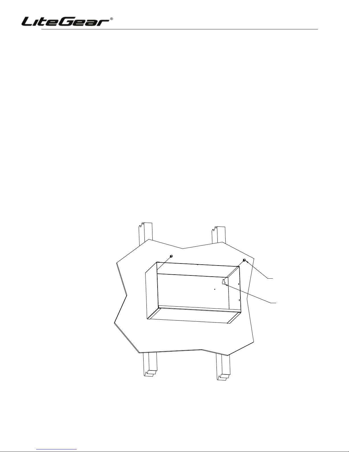
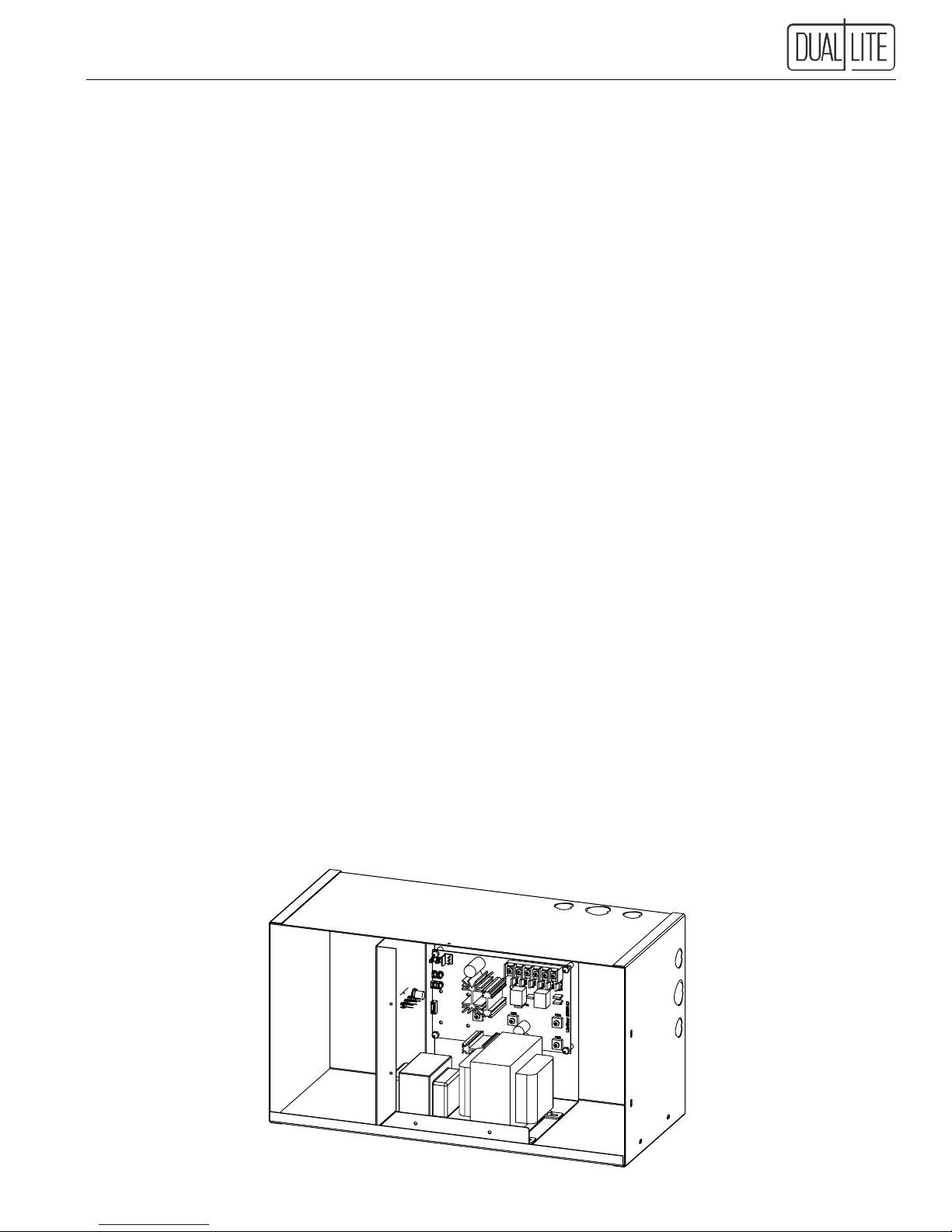
100.2 Cabinet Installation............................................................................................................................................................... 4
101. AC Connections ............................................................................................................................................................ 5-6
101.1 General Precautionary Measures ........................................................................................................................................ 5
101.2 AC Wiring Preparations........................................................................................................................................................ 5
101.3 AC Input Voltage Selection .............................................................................................................................................................. 6
102. LoadCongurationWiringOptions............................................................................................................................ 6-7
102.1 AC Input and AC Output Connections ................................................................................................................................. 6
102.2 "Normally ON" Loads .......................................................................................................................................................... 6
102.3 "Normally OFF" Loads ........................................................................................................................................................ 6
102.4 Externally Switched Loads .................................................................................................................................................. 6
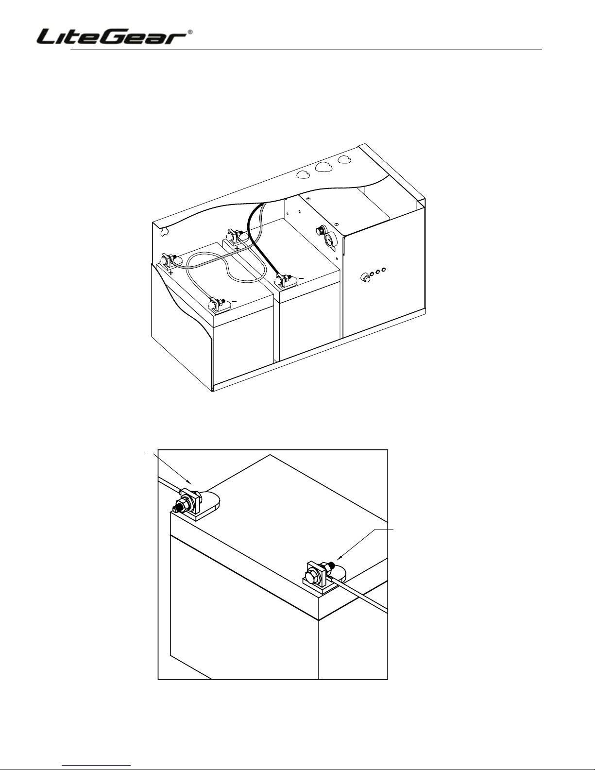
103. Installing the Batteries and DC Wiring ........................................................................................................................ 7-8
103.1 General Precautionary Measures ........................................................................................................................................ 7
103.2 Installation Considerations................................................................................................................................................... 7
103.3 Battery Installation Procedure.............................................................................................................................................. 8
103.4 Electronics Cabinet Voltage Check ...................................................................................................................................... 9
104. Final Installation Checklist .............................................................................................................................................. 9
104.1 Pre-Start-Up Systems Check............................................................................................................................................... 9
105. System Start-Up Procedure ............................................................................................................................................ 9
105.1 Sequence of Steps .............................................................................................................................................................. 9
105.2 Start-Up Procedure Steps.................................................................................................................................................... 9
106. SystemVerication .......................................................................................................................................................... 9
106.1 Initial System Status ............................................................................................................................................................ 9
106.2 System Transfer Test ........................................................................................................................................................... 9
200. Status Indicators ............................................................................................................................................................ 10
200.1 Indicators Provided ............................................................................................................................................................ 10
200.2 Unusual Circumstances ..................................................................................................................................................... 10
201. Spectron® Self-Testing/Self-Diagnostic Option ..................................................................................................... 10-11
201.1 Description and Operation ................................................................................................................................................. 10
201.2 Trouble Shooting Service Alert Code Faults .......................................................................................................................11
202. Remote Test Switch Accessory................................................................................................................................ 11-12
202.1 Installation...........................................................................................................................................................................11
300. Maintenance............................................................................................................................................................... 12-14
300.1 General Precautionary Measures ...................................................................................................................................... 12
300.2 Final Shut Down Procedure ............................................................................................................................................... 12
300.3 Routine System Maintenance ............................................................................................................................................ 12
300.4 Manual Routine Inverter Tests ........................................................................................................................................... 13
300.5 Battery Maintenance and Replacement ............................................................................................................................ 13
300.6 Important Safety Precautions ............................................................................................................................................ 13
300.7 Routine Battery Inspection and Maintenance .................................................................................................................... 13
300.8 Battery Replacement Procedure........................................................................................................................................ 14
300.9 Battery Disposal ................................................................................................................................................................ 14
301. Technical Service and Support ..................................................................................................................................... 14
301.1 Toll-Free Number ............................................................................................................................................................... 14
302. Warranty Information ..................................................................................................................................................... 14
302.1 Warranty ............................................................................................................................................................................ 14