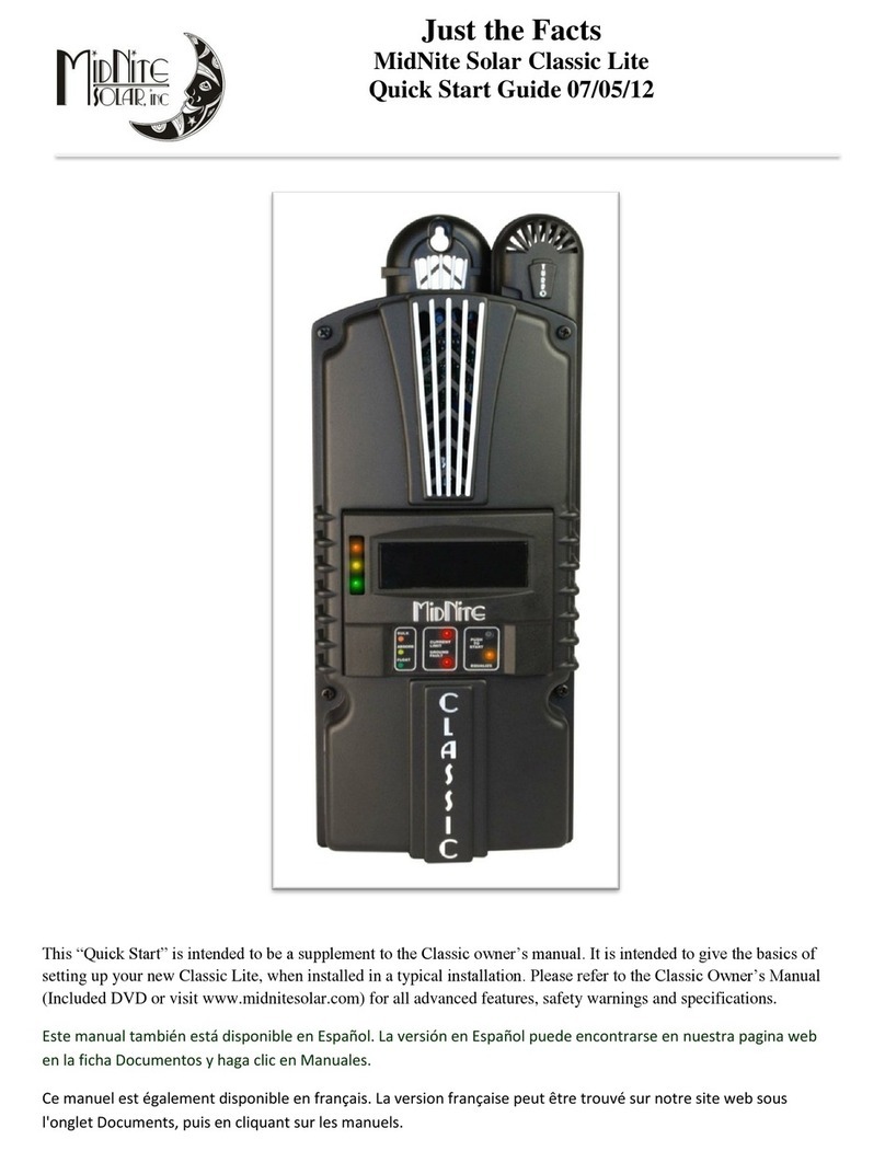
MidNite Solar Rosie MNROSIE7048RE User manual

MNROSIE7048 MANUAL
2| P a g e 1 0 - 4 32- 1 R E V : -
Table of Contents
Introduction ......................................................................................................................... 3
Safety Instructions & Precautions .......................................................................................... 4
How to KILL Your Batteries .................................................................................................... 8
How an Inverter/Charger Works............................................................................................ 9
Wiring Requirements........................................................................................................... 10
DC Wiring and Over-Current Protection ................................................................................... 11
AC Wiring and Over-Current Protection ................................................................................... 13
Grounding / Arc Fault / Ground Fault ....................................................................................... 15
Special Instructions for MNROSIE7048M Mobile Installations .............................................. 15
Installation.......................................................................................................................... 18
Mounting................................................................................................................................... 20
Wiring the Rosie.................................................................................................................. 20
DC Wiring................................................................................................................................... 20
AC Wiring................................................................................................................................... 22
Grounding.................................................................................................................................. 22
Torque Values............................................................................................................................ 25
External Sensors.................................................................................................................. 25
Battery Temperature Sensor..................................................................................................... 26
Current Transformers................................................................................................................ 26
AUX Terminals........................................................................................................................... 26
Whiz Bang Jr .............................................................................................................................. 27
Battery Sense............................................................................................................................. 27
Energizing the Rosie ............................................................................................................ 27
Rosie Programming ............................................................................................................. 29
Rosie MNGP2 Menu Maps................................................................................................... 36
Battery Charging.................................................................................................................. 43
AUX Modes ......................................................................................................................... 45
Firmware Update ................................................................................................................ 46
Technical Drawings and Specifications (CSA TABLE 65.1) ..................................................... 48
Warranty............................................................................................................................. 56

MNROSIE7048 MANUAL
3| P a g e 1 0 - 4 32- 1 R E V : -
INTRODUCTION
The Rosie Inverter/Charger is a battery-based, DC-to-AC inverter and AC-to-DC charger for off-
grid and mobile systems. MidNite offers two Rosie models:
MNROSIE7048RE –a 7000-watt inverter/charger with 60-amp AC transfer relay and
120-amp, multi-stage PFC battery charger. This unit is safety listed to UL1741 and CSA.
The AC IN and OUT have common Neutrals for use in renewable energy (RE) systems
(homes/cabins). The AC Neutral and Ground do not have an internal bond. The bond must be
made in the AC system (commonly at the AC service panel).
MNROSIE7048M –a 7000-watt inverter/charger with 60-amp AC transfer relay and 120-
amp, multi-stage PFC battery charger. This unit is safety listed to UL1741 and CSA. The
AC IN and OUT Neutrals are NOT common to allow automatic neutral-to-ground
switching for Mobile applications (RV, truck, or boat).
•Two AUX terminals with 15 AUX Options per AUX terminal
•ETL Listed to UL1741, UL458, and CSA 107.01 Standards
•100A DC Maximum Batt Charging Current
•State-of-Charge % via the Whiz Bang Jr.
•120/240VAC/60Hz split-phase AC OUT
•Audio Annunciations with Quiet Time
•Battery Temperature Compensation
•Mates with optional Rosie E-panel
•60A transfer relay per 120VAC leg
•Battery Voltage Sense Circuit
•Auto-Gen Start (AGS) menu
•7000W pure sinewave AC
•40 – 65VDC battery IN
•MNGP2 Compatible
•48V battery bank
The optional Rosie E-Panel offers NEC
required OCP and DC disconnects but is
NOT a required component. The Rosie
may be installed without the E-Panel.

MNROSIE7048 MANUAL
4| P a g e 1 0 - 4 32- 1 R E V : -
IMPORTANT SAFETY INSTRUCTIONS
SAVE THESE INSTRUCTIONS
THIS MANUAL CONTAINS IMPORTANT SAFETY INSTRUCTIONS FOR THE MIDNITE SOLAR ROSIE
INVERTER/CHARGER THAT SHALL BE FOLLOWED DURING INSTALLATION AND OPERATION.
If you do not fully understand any of the concepts, terminology, or hazards outlined in these
instructions, please refer installation to a qualified dealer, electrician, or installer. These
instructions are not meant to be a complete explanation of a renewable energy system. Before
using the Rosie, read all instructions and cautionary markings. The installation instructions are
for use by qualified personnel only. Do not perform any installation other than that specified in
this manual unless you are qualified to do so. Incorrect installation may result in a risk of
electric shock, fire, or other safety hazard.
Safety Symbols
The following safety symbols have been placed throughout this manual to indicate dangerous
and important safety instructions.
WARNING indicates a hazardous situation which, if not avoided, could
result in death or serious injury.
WARNING!
CAUTION indicates conditions or practices that could result in damage to
the unit or other equipment.
CAUTION!
INFO: Indicates information that emphasizes or supplements important
points of the main text.

MNROSIE7048 MANUAL
5| P a g e 1 0 - 4 32- 1 R E V : -
SAFETY PRECAUTIONS
•Live power may be present at more than one point since an inverter utilizes both DC
(batteries) and AC (utility or generator) power. To reduce risk of electric shock, ensure all
DC and AC wiring is disconnected prior to installing or performing maintenance on the
inverter. Turning off the inverter will NOT reduce this risk; the inverter must be totally
disconnected from all sources.
•Over-current protection for the AC & DC wiring is not provided as an integral part of this
inverter. Over-current protection of the AC & DC wiring must be provided as part of the
system installation.
•The AC output neutral conductor and the DC negative conductors are not connected (bonded)
to the inverter chassis. Both the input and output conductors are isolated from the enclosure
and each other.
•Battery cables should be no less than #3/0 AWG. Crimped and sealed copper ring terminal
lugs with a 5/16”hole should be used to connect to the DC terminals on the inverter.
•Per CSA 22.2 No. 107.1 Version 2016, Edition 4, Para 5.44, the Rosie regulates within 5% of its
nominal AC output voltage and at 29AAC per 120VAC and 29AAC at 240VAC.
•AC and DC circuit breakers installed as a part of this Rosie inverter/charger system shall
comply with CSA C22.2 No. 235 and meet all the following:
oHave a short-circuit application code of U3;
oHave a tripping current application code of TC3;
oHave an overload code of OL0 or OL1;
▪OL0 –1.5 times the ampere rating for general use; or
▪OL1 –6 times the AC current rating or 10 times the DC current rating for motor
starting applications.
oBe an over-current type or a shunt trip over-current type;
oHave a short circuit current rating not less than the maximum available fault current
under Rosie operating modes;
oBe of a type appropriate for the Rosie’s intended use application.
•System grounding is the responsibility of the system installer and must comply with local and
national electrical codes and standards.
•Per CSA 22.2 No. 107.1 Version 2016, Edition 4, Para 5.37, the voltage rating from circuit
board to ground is no more than 300VAC.
•This product is listed as a Type 1 enclosure, designed for indoor/compartment installation. It
must not be exposed to rain, snow, moisture, or liquids of any type.
•Listed or labeled equipment shall be installed and used in accordance with any instructions
included in the listing or labeling.
•All electrical work must be performed in accordance with local and national electrical codes.
•Use Class 1 wiring methods for field wiring connections to terminals of a Class 2 circuit.

MNROSIE7048 MANUAL
6| P a g e 1 0 - 4 32- 1 R E V : -
oRosie’s Class 2 circuits: CANBUS, Batt Temp Sensor; AUX terminals; WBJr terminal.
•Use insulated tools to reduce the chance of electrical shock or accidental short circuits.
•Turn off all breakers prior to removing front cover and working on the inside of Rosie.
•Only qualified service personnel can remove cover, shock hazards are present.
•The maximum voltage from the printed circuit board to ground is 300VDC.
•Torque all wiring and cable connections to the required torque values.
•All unused conduit holes must be filled with a UL listed conduit plug.
•Use only copper wires with a minimum temperature rating of 90°C.
•The Rosie is provided with integral protection against overloads.
•There are no user-serviceable parts contained in the Rosie.
•Always verify proper wiring prior to starting the inverter.
•The inverter must be properly mounted.
BATTERY SAFETY
•Wear eye protection and avoid touching your eyes and face when working with batteries to
keep any fluid/corrosion on the battery from contact with eyes and skin. Have plenty of fresh
There may be a risk of electric shock from energy stored in capacitors.
Wait 5 minutes after disconnecting battery cables before servicing the Rosie.
CAUTION!
To reduce the risk of fire, connect only to a circuit provided with 60 AC amperes and/or
300 DC amperes maximum branch-circuit over-current protection in accordance with
the National Electrical Code, ANSI/NFPA 70.
CAUTION!
To reduce the risk of fire, do NOT wire the Rosie to an AC load center (circuit breaker
panel) having multiwire branch circuits connected.
WARNING!

MNROSIE7048 MANUAL
7| P a g e 1 0 - 4 32- 1 R E V : -
water and soap nearby and thoroughly wash in case battery acid contacts skin, clothing, or
eyes. In the event of exposure to the eyes, flood them for at least 15 minutes with running
water and seek immediate medical attention. Baking soda neutralizes lead acid battery
electrolyte and vinegar neutralizes spilled NiCad and NiFe battery electrolyte; depending on
your battery type, keep a supply on hand near the batteries.
•Read and follow the battery manufacturer’s safety precautions before installing the inverter
and batteries. Always verify proper polarity and voltage before connecting the batteries
to the inverter. Once the batteries are connected to the inverter, ensure the maintenance
and charging requirements (i.e., charge voltage and charge rate) provided by the battery
manufacturer are followed to extend the life of the batteries and to prevent damage to the
batteries while charging.
•The battery bank should be installed in a clean, dry, ventilated environment that is protected
from high and low temperatures. If installed in a vehicle/boat, the batteries must be mounted
upright (if using liquid batteries) and securely fastened. The location must be fully accessible
and protected from exposure to heat producing devices, and away from any fuel tanks.
•Batteries can produce explosive gasses, so install batteries in a well-ventilated area. For
compartment or enclosure installations, always vent batteries from the highest point to the
outside. Design the battery enclosure to prevent accumulation and concentration of
hydrogen gas in pockets at the top of the compartment.
•Remove all jewelry such as rings, watches, bracelets, etc., when installing or performing
maintenance on the batteries and inverter. A battery can produce a short-circuit current high
enough to weld metal jewelry, causing severe burns.
•Use insulated tools and be very careful when working around batteries, they can produce
extremely high currents if short-circuited (e.g., dropping a metal tool across the battery
terminal), which could cause a fire or explosion.
•When replacing some of the batteries in a bank, always replace with the same model, size, Ah
capacity, charging voltages, and type of the old batteries. Types include: (Flooded, Lithium,
NiFe, sealed, etc.).
•The Rosie will operate with any battery type/form factor (L-16, 2V, golf cart, rectangular, etc.)
or chemistry (lead-acid, Lithium, Nickel Iron, etc.), comprised in a 48VDC nominal bank.
•To prevent a spark at the battery and to reduce the chance of explosion, always connect the
cables to the batteries first. Then connect the cables to the inverter.
•Never work alone. Always have someone within the range of your voice or close enough to
come to your aid when working around batteries.
•Never use old or untested batteries. Check each battery’s label for age, type, and date code
to ensure all batteries are identical.
•Proper disposal of batteries is required. Refer to your local codes for disposal requirements.
•Batteries are sensitive to changes in temperature. Install batteries in a stable environment.

MNROSIE7048 MANUAL
8| P a g e 1 0 - 4 32- 1 R E V : -
•Provide at least one inch of air space between batteries to provide optimum cooling.
•For batteries that require the addition of water, follow these important safety tips:
oElectrolyte Level –NO exposed plates! Ensure plates are covered in electrolyte and
slightly below the bottom “funnel” of the battery fill hole.
oAdd distilled water as needed. Do NOT fill to the bottom of the funnel neck before
you equalize. The electrolyte will probably spill out.
oUse the MidNite Solar’s MNHYDROMETER to measure the specific gravity. Check with
your battery manufacturer for the specific gravity values.
•Use proper lifting techniques when working with batteries.
•Never smoke or allow a spark near batteries.
•Never charge a frozen battery.
STANDARDS
The MidNite Solar Rosie Inverter/Charger conforms to UL 1741, Safety for Inverters, Converters,
Controllers and Interconnection System Equipment for Use with Distributed Energy Resources, UL
1741:2010 Ed.2+R:15Feb2018; CSA C22.2#107.1:2016 Ed.4; and UL 458:2015Ed.6 Power
Converters/Inverters and Power Converter/Inverter Systems for Land Vehicles and Marine Crafts.
HOW TO KILL YOUR BATTERIES
Batteries are delicate and require proper attention, especially when off-grid. Think of your
batteries and solar equipment as a small nuclear power plant, hydro dam, or natural gas-fired
power plant. Just like any of those, your system needs DAILY attention to ensure it is performing
correctly and safely. We recommend the use of an independent battery monitor/alarm if you
have an expensive battery bank. Below is a list of some of the most common ways we have seen
people kill their battery bank.
•Using more than three parallel strings and not using common bus bars. With lead-acid
batteries, when you use more than three strings, it is very hard to properly charge the
A battery can present a risk of electrical shock, burn from high short-circuit current, or
fire or explosion from vented gases with flooded lead-acid batteries.
(NOTE - Sealed batteries do not vent.)
WARNING!

MNROSIE7048 MANUAL
9| P a g e 1 0 - 4 32- 1 R E V : -
middle strings. The only safe way to do this is to wire each string with equal length cables to
a common bus bar. Connect inverter cables to the farthest points on the busbars.
•Not watching to verify the Absorb or EQ times are set properly, and that the equipment
actually charges for that period of time. Some equipment will have settings like “End Amps”
that can terminate Absorb early and, if set up wrong, can damage a battery.
•Not using ALL EQUAL LENGTH interconnect cables on each string. It is important that ALL
strings be wired EXACTLY the same. Any variance in resistance on one string versus another
will cause an imbalance and the batteries will suffer a shortened lifespan.
•Trusting a State of Charge (SOC) meter, which can lose calibration over time and give you
false readings. You need to verify specific gravity and or verify the charge voltage is being
met. Never fully rely on the SOC %; it is just a good, quick reference.
•Routinely using more than 50% of the capacity of the lead acid battery. Using more than half
the battery capacity drastically shortens the batteries life; occasionally is fine, but daily will
kill lead acid batteries in months.
•Not leaving ample space between cells for cooling. We recommend at least one inch
between the cells for cooling. Ask the battery manufacturer what they recommend.
•Not having enough charge current to properly charge the size of the battery you have.
Consult the battery manufacturer for the minimum charge current.
•Using tap water or other liquids instead of distilled water in a flooded battery. The minerals
in the tap water will destroy a battery.
•Not verifying the temperature compensation neutral point (typically 25°C) and the milli volts
per degree C per cell (typically -5mV).
•Not verifying you are charging to the voltage supplied by the battery manufacturer.
•Not fully charging your lead acid batteries at least once a week.
•Failing to keep all connections clean.
HOW AN INVERTER/CHARGER WORKS
Inverter Mode
When the inverter is properly connected to batteries and turned on, the direct current (DC)
from the batteries is transformed into a pure sine wave alternating current (AC). This AC is
similar to the voltage provided by your utility and is used to power any electrical appliances (AC
loads) connected to the inverter’s output.
Standby (Charger) Mode
When an external source of AC power (utility power or generator) is connected and qualified on
the inverter’s AC input, it operates in Standby mode. In Standby mode, the unit operates as a
battery charger to convert the incoming AC power into DC power to recharge the batteries; at

MNROSIE7048 MANUAL
10| P a g e 1 0 - 4 32- 1 R E V : -
the same time, the inverter automatically closes an internal AC transfer relay to pass the
incoming AC power directly to the inverter’s output to continue powering the connected
electrical appliances.
INVERTER APPLICATIONS
Permanent Installations
•An inverter can be used for backup power in a permanent location that normally uses utility
power, such as a home or office. When utility power is available, the inverter keeps the
batteries charged. When the utility power fails, the inverter automatically supplies AC
power to your home or office during the power failure.
•Where utility power is not available, an inverter can be used in a standalone renewable
energy system. The inverter allows AC electrical appliances to be run from the storage
battery bank. When the battery bank becomes discharged, renewable DC sources (solar,
wind, or hydro power) can be used to recharge the batteries via a charge controller, or a
generator can be connected to the inverter to power the system while the batteries
recharge.
Mobile Installations
Inverters can also be used to provide power in mobile situations, such as in an RV, truck, or
boat. In these applications, the inverter provides power to the AC loads using the energy
stored in the batteries and recharges the batteries when shorepower or an onboard generator
is available.
WIRING REQUIREMENTS
•The NEC (National Electric Code, ANSI/NFPA 70) for the United States and the CEC
(Canadian Electrical Code, Part 1) for Canada provide standards for safely wiring residential
and commercial installations. The NEC and CEC list the requirements for wire size, over-
current protection, and installation methods.
•AC and DC wires to and from the inverter must be protected as required by code. This can
be done by using jacketed wires or by feeding the wires through conduit or a conduit box.
•Always check for existing electrical, plumbing, or other areas of potential damage prior to
making cuts in structural surfaces or walls.
•Wiring should meet all local codes and standards and be performed by qualified personnel
such as a licensed electrician.
•The inverter requires a reliable negative and ground return path directly to the battery.

MNROSIE7048 MANUAL
11| P a g e 1 0 - 4 32- 1 R E V : -
•Both AC and DC over-current protection must be provided as part of the installation.
oCoordination of conductor sizes and over-current protection shall be done in
accordance with the Canadian Electrical Code, Part 1.
oNOTE –Breakers protect the wire, not the equipment.
•Use only copper wires with a minimum temperature rating of 90°C.
•The equipment ground is marked with this symbol:
DC Wiring
•Minimize the number of connections between the Rosie and the battery bank. Exceptions
are the DC breaker —required at the battery to protect the DC wiring—in the positive line,
and a DC shunt—to allow battery charge state monitoring—in the negative line. Additional
connections will contribute to voltage drops, and these extra connection points may loosen
during use.
•DC cables should be tied together with wire ties or electrical tape approximately every 6”.
This helps improve the surge capability and reduces the effects of inductance, which
improves the inverter waveform and reduces wear of the inverter’s filter capacitors.
•All wiring to the battery terminals should be checked monthly for proper torque/tightness.
If you don’t have a torque wrench, ensure all DC terminals are tight and cannot move.
•The DC cables/wires must be color coded with colored tape or heat shrink tubing: RED for
positive (+); WHITE for negative (-) if solidly grounded or BLACK if using a GFP breaker; and
GREEN for DC ground.
•Use the correct DC cable and corresponding circuit breaker to achieve maximum efficiency
from the system and reduce fire hazards associated with overheating.
The Rosie is designed for indoor installation or installation inside a weatherproof
enclosure. It must not be exposed to rain and should be installed out of direct sunlight.
CAUTION!
Ensure all sources of DC power (batteries) and AC power (utility or AC generator) are
de-energized (breakers opened, fuses removed) before proceeding—to prevent
accidental shock.
WARNING!

MNROSIE7048 MANUAL
12| P a g e 1 0 - 4 32- 1 R E V : -
•The DC cables must be fine strand, super flexible, such as Cobra cable (or equivalent) and be
approved for residential wiring per the NEC (THW for example).
•Do not use the inverter’s chassis in place of the battery negative connection for grounding.
The inverter requires a reliable return path directly to the battery.
•Use tinned copper 5/16” terminal lugs on the DC cables. Crimp the lugs on, then heat-
shrink the union of cable to lug.
•A readily accessible battery disconnect is required and must be located within sight of the
battery system (NEC 480.7).
oIf the batteries are external to the location of the Rosie, then the battery installation
must be done in accordance with the storage battery rules of the Canadian Electrical
Code, Part 1.
•Ensure cables have a smooth bend radius and do not become kinked. Follow existing wire
runs where possible.
•Ensure both DC cables pass through the same knockout and conduit to allow the inductive
currents to cancel.
•Install a 300A DC breaker between the Rosie and the battery bank on the positive cable.
•Limit cable length to 6’ or less from Rosie to battery bank.
•The battery bank voltage MUST be 48V!
DC Over-Current Protection
•The NEC requires both over-current protection (UL489 standards) and a disconnect switch.
If a circuit breaker is used as the over-current protection device, it can also be used as the
required DC disconnect. If a fuse is used as an over-current device, a Class-T type or
equivalent is highly recommended. This fuse type is rated for DC operation, can handle high
short-circuit currents, and has a time delay that allows for momentary current surges from
the inverter without opening the fuse. Because the fuse can be energized from both
directions, the NEC requires that it be installed in a manner that the power must be
disconnected on both ends of the fuse before servicing.
•The DC over-current protection device must be installed on the positive DC cable, and it
must be correctly sized according to the size of DC cables being used, which means it is
required to open before the cable reaches its maximum current carrying capability.
Verify correct polarity with a multimeter BEFORE connecting the battery cables to the Rosie.
The Rosie will trip the battery breaker if wired reverse polarity.
WARNING!

MNROSIE7048 MANUAL
13| P a g e 1 0 - 4 32- 1 R E V : -
•DC over-current protection is not included with the Rosie and must be provided as part of
the inverter installation. Use a 300A DC breaker.
AC Wiring
•When wiring the AC input and output circuits, we recommend a full system Inverter Bypass
Switch, which provides a convenient means to isolate the inverter for battery maintenance
and to continuously power AC loads without any re-wiring.
•The wire sizes recommended in this manual are based on the ampacities given in Table
310.17 (in free air) of the NEC, ANSI/NFPA 70, for 90ºC copper wire based on an ambient
temperature of 30ºC (86ºF).
•Always use properly rated circuit breakers. If using an electrical sub-panel, circuit breakers
can be moved from the main electrical panel to the sub-panel only if the breakers are also
listed to be installed in the sub-panel.
•The AC wiring must be protected from short circuits and overloads by an over-current
protection device (UL1077 standards) and have a means to disconnect the AC circuits.
•An AC generator wired into the Rosie must have an emergency shutdown device located
outside the dwelling at a readily accessible location (NEC 445.18).
•DO NOT connect the inverter’s output to an external AC power source. This could cause
severe damage to the inverter and is not covered under warranty.
•AC loads powered by the inverter will need to be installed into an electrical sub-panel with
branch breakers to power the AC loads.
•The AC IN and OUT neutrals are common and may be wired to a common neutral bus.
Mobile Installations (MNROSIE7048M)
•The AC IN and OUT neutrals must be isolated from each other. Do not route the AC IN and
OUT neutrals to a common neutral bus. See page 15 for important information on Mobile
Installations.
•Use #6 AWG (or larger), 600V wire for the AC IN and AC OUT wires.

MNROSIE7048 MANUAL
14| P a g e 1 0 - 4 32- 1 R E V : -
AC Ground Fault Circuit Interruption (GFCI)
UL standards require the use of GFCI outlets or breakers on the AC output of an inverter.
AC Over-Current Protection
•Over-current protection for power-feeder conductors from the inverter shall be within
seven inches of the output connections or may be within 40 inches of the output
connections if the unprotected insulated conductors are contained throughout their entire
distance in a sheath or enclosure such as a conduit/junction box or enclosed panel. The
optional Rosie Breaker Box satisfies this requirement.
•The full AC continuous pass-thru capacity of the Rosie inverter/charger is limited to
60A. AC IN to AND AC OUT from the inverter require 60A continuous duty rated breakers,
which corresponds to a minimum cable size of #6 AWG.
•The AC over-current protection device must be a circuit breaker or a fuse/disconnect and be
properly sized and branch circuit rated for the wire it is protecting and the appliances being
powered.
•AC over-current protection is not included with the Rosie and must be provided as part of
the inverter installation.
Grounding
•The negative battery conductor should be solidly bonded to the grounding system at only
one point in the system. The size for the conductor is determined by the size of the largest
phase conductor, per the NEC/CEC.
Do NOT connect the Rosie’s AC OUT to an external AC power source.
WARNING!
•AC wiring must be no smaller than #6 AWG gauge copper wire.
•The Rosie’s internal AC transfer relay is rated at 60A. The pass-through current
cannot exceed 60A or damage to the relay will occur.
CAUTION!
RISK OF ELECTRIC SHOCK! Use only ground-fault circuit interrupters [receptacle(s) or circuit
breaker(s)] compatible with your inverter/charger.
WARNING!

MNROSIE7048 MANUAL
15| P a g e 1 0 - 4 32- 1 R E V : -
•The AC neutral and equipment ground should only be bonded in one location for the entire
system.
•More grounding information provided on pages 22-25.
Arc Fault - The NEC requires any PV system DC circuit operating at 80VDC or greater must be
protected by an arc fault (AF) circuit interrupter.
Ground Fault - Since 2008 the NEC requires a DC Ground Fault (GF) Protection device on all
PV systems to indicate when a GF condition exists.
Protecting Wire –ROSIE Breaker Box (MNE300ROSIE-240)
The AC and DC wires to and from the Rosie must be protected as required by code. This can be
done by using jacketed wires or by feeding the wires through conduit. Midnite offers a breaker
box that includes the necessary AC and DC inverter breakers that allow both the AC and DC
conduit to be connected to the inverter.
SPECIAL INSTRUCTIONS FOR MNROSIE7048M INSTALLATIONS
Grounding on Boats
When installing the MNROSIE7048M on a boat, there are several considerations that must be
followed when grounding to ensure a safe installation, to prevent galvanic corrosion, and to
adhere to American Boat and Yacht Council (ABYC) standards.
Ensure a Safe Ground Connection
•When AC on the boat is being supplied by shorepower, the onboard neutral should be
connected to safety ground on the dock. Consequently, neutral and safety ground should
not be connected anywhere on the boat when shorepower is present. When AC on the
boat is being supplied by the Rosie, the Rosie’s output neutral is connected to safety ground
through an internal relay, using its neutral-to-ground connection.
•The DC ground terminal on the Rosie must also be connected to the boat’s safety ground
bus. This ensures that both the inverter’s AC and DC ground terminals are connected to the
The Rosie may be used in a positive grounded or negative grounded installation. For a
grounded system, bond either Battery Negative to Ground, or bond Battery Positive to
Ground (but not both at the same time!!).
CAUTION!

MNROSIE7048 MANUAL
16| P a g e 1 0 - 4 32- 1 R E V : -
boat’s safety ground bus as a safety measure to provide protection against faults, and to
provide a path for AC fault currents while the boat is connected to shorepower.
Preventing the Risk of Corrosion
•The inverter’s AC and DC ground terminals must be connected to the boat’s safety ground
to provide an important safety feature. However, this ground connection introduces the
risk of galvanic corrosion and/or electrolysis of the boat’s underwater metallic hardware.
Two possible solutions are typically used to maintain the correct onboard grounding
requirements while greatly reducing (if not eliminating) the risk of galvanic corrosion. These
solutions would be either using a galvanic isolator or an onboard isolation transformer.
Galvanic isolators allow high AC voltage faults to pass but block low voltage
corrosion/electrolysis currents from conducting.
•Marine isolation transformers allow the shorepower to be connected to one side of the
transformer, and the boat’s AC wiring system is connected to the other side. Since
transformers do not allow DC currents to pass, the problem with galvanic corrosion is
eliminated.
ABYC Inverter/Charger Grounding Requirements
DC Grounding Connections:
•The DC grounding conductor (equipment ground) shall be:
oConnected from the metallic case or chassis of the inverter/charger to the engine
negative terminal or its bus,
oof an ampacity equal to that of the DC positive conductor (under certain conditions,
there is an exception to allow this conductor to be one size smaller—refer to the
ABYC standard).
•The inverter/charger’s negative battery terminal and DC grounded conductor (negative
cable) shall not be connected to the inverter case or chassis at the inverter/charger
itself.
The converter/inverter is intended to recharge batteries. The battery that is connected to this
product is only suitable if it complies with the given battery standard for that battery type and is
provided with a battery management system that will monitor and control the electrical and
thermal health of the battery during charging. When installing this converter/inverter, the
battery is to be verified as in compliance with the applicable battery standard.
CAUTION!

MNROSIE7048 MANUAL
17| P a g e 1 0 - 4 32- 1 R E V : -
AC Grounding Connections:
•The AC grounding conductor (green) shall be connected to the inverter/charger in a
manner so that the AC ground connection will not be disconnected in servicing. This
conductor is in addition to and independent of the DC grounding conductor.
•The neutral for AC power sources shall be grounded only at the following points:
oThe shorepower neutral is grounded only through the shorepower cable and not
grounded on board the boat.
oThe inverter neutral shall be grounded at the inverter, and the output neutral shall
be disconnected from ground when the inverter is operating in the charger/pass-
through mode.
oOn systems using an isolation transformer or a polarization transformer, the inverter
neutral (and the transformer secondary neutral) may be grounded at the AC main
grounding bus instead of at the inverter.
Neutral to Safety Ground Bonding
•The standards for safely wiring residential, commercial, RV/truck, and marine
installations in the United States require the neutral and safety ground to be connected
at the AC source; whether it is the utility feed in your home, an inverter, or a generator.
This ensures a circuit breaker will activate if a hot wire-to-ground fault occurs. The
Standards also require that the AC neutral be connected to safety ground (often called a
“bond”) in one, and only one, place at any time. The single bond is established to make
the electrical panel’s neutral line safe, by connecting it to ground. Without this bond,
the neutral can have up to 60VAC with respect to ground. If more than one bond is
established, currents can circulate between neutral and ground and cause “ground-
loop” currents, which can trip GFCIs and/or cause an electric shock hazard.
•In applications where you are using an inverter as one of your AC sources along with
another AC source (i.e., utility power or generator), there is the potential of having
multiple connections (bonds) between neutral and ground. Therefore, you MUST
ensure that the inverter does not also connect the neutral-to-ground while the other AC
source is actively powering the inverter loads. This can be prevented if your inverter is
equipped with automatic neutral-to-ground switching, which the Rosie offers.
The onboard neutral is not directly connected to safety ground on the dock if an
isolation transformer is installed. See the ABYC Standard for complete AC/DC
grounding requirements.

MNROSIE7048 MANUAL
18| P a g e 1 0 - 4 32- 1 R E V : -
•The MNROSIE7048M has
automatic neutral-to-
ground switching to
specifically work in mobile
(i.e., truck/RV/boat)
applications.
•The MNROSIE7048M uses
an internal relay (Figure 1)
that automatically connects
the AC neutral output terminal to the vehicle/ boat’s ground while inverting (Inverter
mode) to provide the neutral-to-ground bond. However, when an external AC source
(i.e., shorepower or a generator) is connected, another neutral-to-ground connection is
introduced in the system.
•When the MNROSIE7048M is connected to this external AC source and goes into
Standby mode, the internal relay automatically opens the neutral-to-ground connection.
This design keeps two neutral-to-ground connections from occurring at the same time,
thereby preventing an electrical shock hazard between the vehicle/boat’s neutral and
the external AC source’s neutral.
INSTALLATION
Before installing, read the entire installation section to determine how you are going to install
your Rosie. The more thoroughly you plan in the beginning, the better your overall system
needs will be met.
Location Considerations
•Locate the Rosie as close to the batteries as possible. Long DC wires tend to lose efficiency
and reduce the overall performance of an inverter. However, the unit should not be
mounted where it will be exposed to gases produced by the batteries. These gases are
corrosive and will damage the inverter; also, if these gases are not ventilated and if allowed
to collect, they could ignite and cause an explosion.
Rosie Inverter
Mode
Rosie Standby
Mode
Figure 1
In most electrical systems, the neutral-to-ground bond is located in the main utility service
entrance panel. Remove any bond downstream from the inverter to prevent multiple bonds.
If there is an inverter sub-panel—separate from a main electrical panel—it should have a
removable wire that allows the neutral bus to be unbonded from the ground busbar.
WARNING!

MNROSIE7048 MANUAL
19| P a g e 1 0 - 4 32- 1 R E V : -
•The NEC requires 30” clear on the wall. The Rosie may be located anywhere within this 30”.
The NEC also requires 36” free and clear of obstructions in front of the charge controller.
The 36” clear area in front of all electrical panels is to provide a space to fall back into in
case of electrical shock.
•Do not cover or block the Rosie’s ventilation openings or install in an area with limited
airflow. The Rosie uses four fans to provide forced air cooling; allow at the minimum an
airspace clearance of 6” at the vents and 3” everywhere else to provide adequate
ventilation.
•The area must be free from any risk of condensation, water, or any other liquid that can
enter or fall on the inverter. The Rosie is indoor rated and should not be placed outside
unless precautions are taken to keep rain and moisture off the system.
•Ensure the Rosie is accessible after it is mounted. The Rosie is programmed and data points
monitored via a remotely-mounted MNGP2 (MidNite Graphics Panel). You will need to
access the MNGP2 during and after installation.
•The Rosie should be protected from direct sun exposure or equipment that produces
extreme heat. The ambient temperature around the Rosie must not exceed 77°F (25°C) to
meet power specifications.
•If installed in an enclosure, a fresh air intake opening must be provided directly to the
bottom side (intake vents) of the inverter and an exhaust opening on the top side (exhaust
vents) of the inverter.
•Keep any flammable/combustible material (e.g., paper, cloth, plastic, etc.) that may be
ignited by heat, sparks, or flames at a minimum distance of 2’away from the inverter.
•Mount at least 2’ from any flammable or combustible fluid or components (i.e., paper,
cloth, plastic, etc.) that may be ignited by heat, sparks, or flames.
•Do NOT install the Rosie in an area that contains extremely flammable liquids like
gasoline or propane.
•The Rosie is for use in non-hazardous locations in accordance with the rules of CSA
C22.1, Canadian Electrical Code, Part I.
WARNING!
Do NOT mount this inverter in a zero-clearance compartment, nor cover or obstruct the
ventilation openings—overheating may result.
CAUTION!

MNROSIE7048 MANUAL
20| P a g e 1 0 - 4 32- 1 R E V : -
•The Rosie should not be installed in an area that allows dust, fumes, insects, or rodents to
enter or block the ventilation openings.
•The Rosie weighs 43.5 pounds. The mounting surface and hardware must be capable of
supporting at least twice the weight.
•Plan any conduit runs now. Typical wiring and routing examples:
oAC IN from Grid or Genny or transfer switch
oAC OUT to service or sub-panel
oDC cables to battery bank
oBattery Temp Sensor
•Mount vertically on a flat, non-combustible surface.
Mounting –Rosie (Figure 2)
1. Determine mounting location.
2. Hold Rosie to wall, mark bolt holes; set Rosie aside.
3. Install top two lag bolts to wall, leaving about ¼” exposed.
4. Hang Rosie on top two bolts, install bottom two bolts.
5. Tighten lag bolts.
Mounting –Rosie and E-Panel -If mating the Rosie with the E-panel, refer to the E-Panel
Manual for installation and wiring.
WIRING THE ROSIE
•Take note of the terminal blocks and wiring connection points of the Rosie, Figures 3 & 4.
•Reference overall system wiring diagram on page 48.
•There are no servicing (adjustment) points for the system owner inside the Rosie.
•Always turn off circuit breakers (remove fuses) BEFORE wiring the Rosie.
•After the Rosie is wired and operational, and with the front cover removed, be mindful that
the active circuit boards and terminal blocks contain AC and DC voltages and current!
DC Wiring (Figures 5 & 6)
1. Connect #3/0 AWG Batt+ and Batt- cables to the Rosie DC terminals.
2. Pass the Batt+ cable through a 300A circuit breaker (UL489). Turn OFF the 300A breaker.
3. Connect battery cables to the battery bank master positive and negative terminals.
4. Torque Rosie terminal nuts to 10-12 ft-lbs. Page 28 for torque specs.
5. Install DC terminal safety caps. (Figure 6)
6. Torque batt bank connections to batt manufacturer specs.
Figure 2
This manual suits for next models
1
Table of contents
Other MidNite Solar Inverter manuals

MidNite Solar
MidNite Solar MNPV8 series User manual

MidNite Solar
MidNite Solar MNKID-B User manual

MidNite Solar
MidNite Solar Brat User manual

MidNite Solar
MidNite Solar Rosie MNE300ROSIE-240P User manual

MidNite Solar
MidNite Solar Classic Lite User manual

MidNite Solar
MidNite Solar MN5048DIY User manual
Popular Inverter manuals by other brands

Analytic Systems
Analytic Systems Pure Sine 300 Installation and operation manual

Power Products
Power Products LIMITED 2000I Instructions for use

TECO
TECO F510 series instruction manual

INVT
INVT Goodrive350 Series Operation manual

Srne
Srne HF2430S80-H user manual

Senci
Senci SC13000 Safety instructions & operator's manual