WESTECH VS Series User manual

VS series
—— Solar Charge Controller
Thank you very much for selecting our product!
This manual offers important information and suggestions with respect
to installation, use and troubleshooting, etc. Please read this manual
carefully before using the product and pay attention to the safety
recommendations in it.
INSTRUCTION
MANUAL

—— Solar Charge Controller
Nominal system voltage
12V∕24V∕48V
Nominal charge / discharge current
10A∕20A∕30A∕40A∕50A∕60A
VS

Contents
1 Important Safety Information ............................................................................1
2 General Information..........................................................................................2
2.1 Product Overview.................................................................................2
2.2 Product Features...................................................................................3
2.3 Optional Accessories ............................................................................5
3 Installation Instructions.....................................................................................6
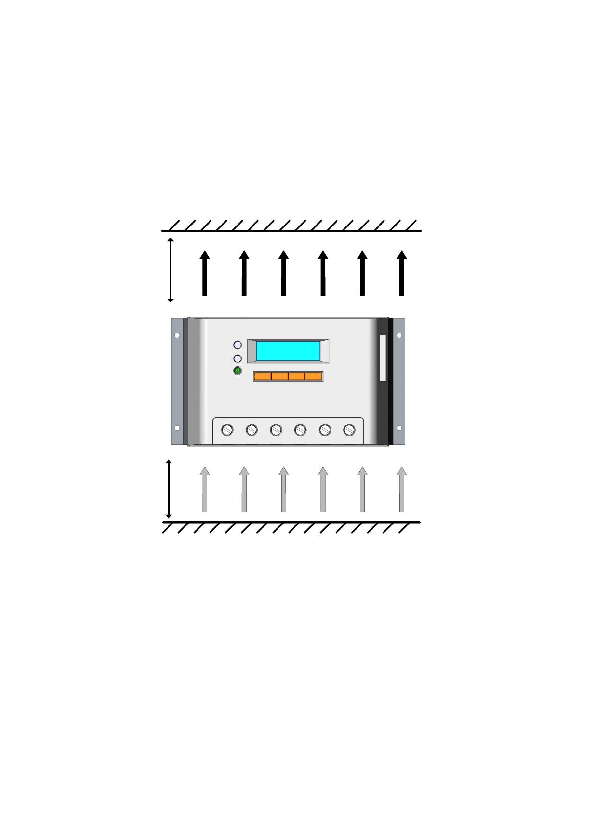
3.1 Mounting..............................................................................................6
3.2 Wiring..................................................................................................8
4 Operation........................................................................................................11
4.1 PWM Technology...............................................................................11
4.2 Battery Charging Information.............................................................11
4.3 HMI Interface.....................................................................................13
4.4 Operation and Displaying of Controller ..............................................15
System Monitor Interface...............................................17
Device Setting Interface.................................................20
Charging and Discharging Parameters Setting Interface.22
Load Control Interface...................................................25
Nominal Parameter Interface..........................................31
Factory Reset Interface..................................................32
5 Protection, Troubleshooting and Maintenance.................................................34
5.1 Protection...........................................................................................34
5.2 Troubleshooting..................................................................................35
5.3 Maintenance.......................................................................................38
6 Warranty.........................................................................................................39
7 Technical Specifications..................................................................................40

1
1 Important Safety Information
Save These Instructions
This manual contains important safety, installation and operating instructions.
The following symbols are used throughout this manual to indicate potentially dangerous
conditions or mark important safety instruction, please take care when meeting following
symbols.
WARNING: Indicates a potentially dangerous condition.
Use extreme caution when performing this task.
CAUTION: Indicates a critical procedure for safe and
Proper operation of the controller.
General Safety Information
Read all of the instructions and cautions in the manual before beginning installation.
There are no user serviceable parts inside the controller. Do not disassemble or attempt
to repair it.
Install external fuses/breakers as required.
Disconnect the solar module and fuse/breakers near to battery before installing or
adjusting the controller.
Do not allow water to enter the controller.
Confirm that power connections are tightened to avoid excessive heating from loose
connection.

2
2 General Information
Thank you for selecting VS series solar charge controller that adopts the most advanced
digital technique, displays on the LCD and operates fully automatically. The Pulse
Width Modulation (PWM) battery charging and the unique control technology can
greatly increase the lifetime of battery. It has various unique functions and easy to use.
2.1 Product Overview
The controller is for off-grid solar system, and protects the battery from being over
charged by the solar module and over discharged by the loads. The charging process has
been optimized for long battery life and improved system performance. The
comprehensive self-diagnostics and electronic protection functions can prevent damage
from installation mistakes or system faults.
Features:
32 bit MCU with high speed and high performance
12 bit A/D high-precision sampling to ensure accuracy
Excellent EMC design
Nominal system voltage automatic recognition
High efficient Series PWM charging, increase the battery lifetime and improve the solar
system performance
Use MOSFET as electronic switch, without any mechanical switch
Widely used, automatically recognize day/night
Adopt graphics dot-matrix LCD screen and HMI (human-machine interface) with 4
buttons, integrated menu displaying and operation
Humanized design of browser interface, undertake every operating conveniently
Full control parameters setting and modification, diversified load control mode
Gel, Sealed and Flooded battery type option
Adopt temperature compensation, correction algorithm for charging and discharging
parameters automatically and improve the battery lifetime
Electronic protection: Overheating, over charging, overdischarging, overload, and short circuit.
Reverse protection: any combination of solar module and battery

3
2.2 Product Features
1
3
6
7
8
9
2
10
4
5
1
2
3
4
5
10
6
7
8
9
VS1024(N) / VS2024(N)
VS2048(N) / VS30**(N) / VS40**(N) / VS50**(N) / VS60**(N)

4
1–Local temperature sensor
It is used for acquisition of ambient temperature to undertake temperature compensation
of charging and discharging parameters, when the remote temperature sensor is not
connected
2–Fault LED indicator
An LED indicator that shows faults of solar system
3–Charging LED indicator
An LED indicator that shows charging status
4–Liquid crystal display (LCD)
Monitoring interface for solar system parameters
5–Combined-type buttons
4 combined-type buttons accomplish all operations to controller
6–Communication interface
Connect remote displaying unit MT-100 (Optional Accessories)
7–Load terminals
Connect loads
8–Battery terminals
Connect batteries
9–Solar module terminals
Connect solar modules
10 –Remote temperature sensor interface
Connect remote temperature sensor TS-R (Optional Accessories) to acquire of ambient
temperature for undertaking temperature compensation of charging and discharging
parameters, when it is in connection.

5
2.3 Optional Accessories
1. Remote Meter(Model:MT-100)
The digital Remote Meter displays system operating information, error indications, and
self-diagnostics read-out. Information is displayed on a backlit LCD display. The large
numerical display and icons are easy to read and large buttons make navigating the meter
menus easy. The meter can be flush mounted in a wall or surface mounted using the
mounting frame (included). The MT-100 is supplied with 1.5m of cable and a mounting
frame. The MT-100 connects to the RJ45 port on the VS.
2. Remote temperature sensor (Model:TS-R)
Acquiring of ambient temperature for undertaking temperature compensation of charging
and discharging parameters, the standard length of the cable is 2m (can be customized if
want longer or shorter). The TS-R connects to the 2ERJ—3.81 port on the VS.

6
3 Installation Instructions
3.1 Mounting
Read through the entire installation section first before beginning installation.
Be very careful when working with batteries. Wear eye protection. Have fresh water
available to wash and clean any contact with battery acid.
Uses insulated tools and avoid placing metal objects near the batteries.
Explosive battery gasses may be present during charging. Be certain there is sufficient
ventilation to release the gasses.
Avoid direct sunlight and do not install in locations where water can enter the controller.
Loose power connections and/or corroded wires may result in resistive connections that
melt wire insulation, burn surrounding materials, or even cause fire. Ensure tight
connections and use cable clamps to secure cables and prevent them from swaying in
mobile applications.
Use with Gel, Sealed or Flooded batteries only.
Battery connection may be wired to one battery or a bank of batteries. The following
instructions refer to a singular battery, but it is implied that the battery connection can
be made to either one battery or a group of batteries in a battery bank.
Select the system cables according to 3A/mm2current density
NOTE: When mounting the controller, ensure free air through the
controller heat sink fins. There should be at least 6 inches (150 mm)
of clearance above and below the controller to allow for cooling. If
mounted in an enclosure, ventilation is highly recommended.
WARNING: Risk of explosion! Never install the controller in a
sealed enclose with flooded batteries! Do not install in a confined
area where battery gassed can accumulate.

7
Step 1: Choose Mounting Location
Locate the controller on a vertical surface protected from direct sun, high temperature,
and water. And make sure good ventilation.
Step 2: Check for clearance
Place the controller in the location where it will be mounted. Verify that there is sufficient
room to run wires and that there is sufficient room above and below the controller for air
flow.
Step 3: Mark Holes
Use a pencil or pen to mark the four (4) mounting hole locations on the mounting surface.
Step 4: Drill Holes
Remove the controller and drill 4mm holes in the marked locations.
Step 5: Secure Controller
Place the controller on the surface and align the mounting holes with the drilled holes in
step 4.
Secure the controller in place using the mounting screws.
Warm air
Cool air
150mm(5.9inches)
150mm(5.9inches)

8
3.2 Wiring
NOTE: A recommended connection order has been provided for
maximum safety during installation.
NOTE: There are two types of the controller: common positive
controller and common negative controller.
CAUTION: Don’t connect the loads with surge power exceeding the
ratings of the controller.
CAUTION: For mobile applications, be sure to secure all wiring.
Use cable clamps to prevent cables from swaying when the vehicle is
in motion. Unsecured cables create loose and resistive connections
which may lead to excessive heating and/or fire.
WARNING: Risk of explosion or fire! Never short circuit battery
positive (+) and negative (-) or cables.
WARNING: Risk of electric shock! Exercise caution when handling
solar wiring. The solar module(s) high voltage output can cause
severe shock or injury. Be careful operation when installing solar
wiring.
Before battery is connected, make sure that voltage of battery is higher than 9V so as to
start the controller. If nominal system voltage is 24V, make sure that voltage of battery is
no less than 18V; if nominal system voltage is 48V, make sure that voltage of battery is no
less than 42V. The nominal system voltage can only be automatically identified when
controller is started for the first time.

9
Controller’s load terminals can be connected to DC electric equipments whose nominal
operation voltage is the same as nominal voltage of battery. The controller supplies power
to loads with battery voltage.
It is suggested that positive pole or negative pole of battery and loads should be
connected to a safety device, whose operation current is not twice lower than nominal
charging or discharging current. Do not switch on the safety device while it is being
installed. Switch on the safety device after the wiring is confirmed to be correct.
CAUTION: On occasions that controller must be connected to the
ground. For common positive controller, the positive pole must be
connected to the ground, on the contrary, the negative pole must be
connected to the ground for common negative controller.
﹡Wire conductor length:
VS1024(N) :7mm
VS20**(N) :13mm
VS30**(N) :10mm
VS40**(N) / VS50**(N) / VS60**(N) :14mm

10
Step 1: Wiring and switching on
After solar system is wired, check carefully all wirings so as to make it clear whether all 6
terminals are correctly connected and tightened. According to the order of switching on in
the chart, battery first, loads second and solar module third successively to avoid nominal
system voltage identification error.
Step 2: Confirming power on
When controller starts up, liquid crystal display (LCD) displays initialization interface
and 2 indicator lamps will be lightened once, check if it is correct. If there are no above
procedures, refer to section 5 for troubleshooting.
Solar Module
Fuse
Load
Fuse
Battery
1
3
2
+
-
-
+
+
-

11
4 Operation
4.1 PWM Technology (Series Pulse Width Modulation)
The controller adopts the advanced series pulse width modulation (PWM) charging mode.
With range of 0-100%, it can charge the battery quickly and stably under any condition of
solar photovoltaic system.
PWM charging mode use automatic conversion duty ratio pulses current to charge the
battery. The battery can be fully charged safety and rapidly with the pulse current.
Intermissions make some oxygen and hydrogen generated by chemical reaction
chemically combined again and absorbed. It can eliminate concentration polarization and
ohm polarization naturally and reduce the internal pressure of the battery so that the
battery can absorb more power. Pulse current charging mode makes battery have more
time to react, which reduces the gassing volume and makes battery improve the
acceptance rate of charging current.
4.2 Battery Charging Information
·Bulk Charge
In this stage, the battery voltage has not yet reached boost voltage and 100% of available
solar power is used to charge the battery.

12
·Boost Charge
When the battery has recharged to the Boost voltage setpoint, constant- current regulation
is used to prevent heating and excessive battery gassing. The Boost stage remains 120
minutes and then goes to Float Charge. Every time when the controller is powered on, if
it detects neither over discharged nor overvoltage, the charging will enter into boost
charging stage.
·Float Charge
After the battery is fully charged in Boost voltage stage, the controller reduces the battery
voltage to Float voltage set point. When the battery is fully recharged, there will be no
more chemical reactions and all the charge current transmits into heat and gas at this time.
Then the controller reduces the voltage to the floating stage, charging with a smaller
voltage and current. It will reduce the temperature of battery and prevent the gassing, also
charging the battery slightly at the same time. The purpose of Float stage is to offset the
power consumption caused by self consumption and small loads in the whole system,
while maintaining full battery storage capacity.
In Float stage, loads can continue to draw power from the battery. In the event that the
system load(s) exceed the solar charge current, the controller will no longer be able to
maintain the battery at the Float setpoint. Should the battery voltage remains below the
boost reconnect charging voltage, the controller will exit Float stage and return to Bulk
charge.
·Equalize Charge
WARNING: Risk of explosion!
Equalizing flooded battery can produce explosive gases, so well
ventilation of battery box is necessary.
NOTE: Equipment damage!
Equalization may increase battery voltage to the level damaging to
sensitive DC loads. Ensure that all load allowable input voltages are
greater than the equalizing charging set point voltage.

13
NOTE: Equipment damage!
Over-charging and excessive gas precipitation may damage the
battery plates and activate material shedding on them. Too high an
equalizing charge or for too long may cause damage. Please
carefully review the specific requirements of the battery used in the
system.
Certain types of batteries benefit from periodic equalizing charge, which can stir the
electrolyte, balance battery voltage and complete chemical reaction. Equalizing charge
increases the battery voltage, higher than the standard complement voltage, which
gasifies the battery electrolyte.
Every month 28th solar controller will engender equalize charging stage. It will remain
120mins when equalize stage is constant, or it will remain 180mins when equalize
charging accomplishes off and on. Equalize charge and boost charge are not carried out
constantly in a full charge process to avoid too much gas precipitation or overheating of
battery.
4.3 HMI Interface
Charging indicator
MENU/←
↑/ +
↓/ -
ENTER/→
LCD
!
WELCOME
VERSION 1.1
Fault indicator

14
■Buttons instruction:
Charging indicator
GREEN ON whenever sunlight is available for battery charging,
Charging LED indicator Table 4-1
Color
Indicator
Charging Status
Green
On Solid
Charging
Fault indicator
When the following cases occur, fault indicator red flashing:
Solar module: Over current, Measure error of voltage, Short of counter-attack MOS-I,
Short of charging MOS-C, MOS-I or MOS-C disconnection or MOS break in control
section;
Battery: Over voltage, Measure error of voltage, Over temp;
Load: Over load, Short, Short of discharging MOS, Measure error of voltage;
Device: Over temp.
For trouble shooting, refer to chapter 5.
MENU/←
↓/ -
↑/ +
ENTER/→
:Menu / Cursor left button
:Cursor up / Number add button
:Cursor down / Number reduce button
:Enter / cursor right button

15
Fault LED indicator Table 4-2
Color
Indicator
Charging Status
Red
Flashing
PV:OverCurrent、Measure Err、MOS-I
Short、MOS-C Short、MOS Break
BATT:OVD、Error、OverTemp
LOAD:Overload、Short、
MOS Short、Error
DEVICE:OverTemp
4.4 Operation and Displaying of Controller
Load work mode
1. Dusk to Dawn
When solar module voltage goes below the point of NTTV (Night Time Threshold
Voltage) at sunset, the controller will recognize the starting voltage and turn on the load
after configurable delay time. When solar module voltage goes above point of DTTV
(Day Time Threshold Voltage), the solar controller will recognize the starting voltage and
turn off the load after configurable delay time.
2. Light ON + Timer
When solar module voltage goes below the point of NTTV (Night Time Threshold
Voltage) at sunset; the solar controller will recognize the starting voltage and turn on the
load after configurable delay time. The load will be on for several hours which users set.
3. Timer
The mode includes single and double time intervals. Set the starting and ending time for
each time interval and controller works according to the set time interval.
4. Manual mode
This mode is to turn ON and OFF the load by manual.

16
Operation and displaying of controller
Initialization Interface
When controller is powered on, it turns into initialization, refer to the following picture:
Main Menu Interface
When controller is initialized, it is automatically turned into monitoring interface. Press
button to turn into main menu 1 interface which displays the following
contents:
Press the button continuously, entering into main menu 2 interface which
displays the following contents:
WELCOME
VERSION 1.1
1.Monitoring
2.Device Set
3.Parameter Set
4.Load Set
MENU/←
5.Rated Value
6.Factory Reset
Inverse cursor showing
the contents can be
operated
↓/ -

17
System Monitor Interface
In the main menu interface, when press or , the inverse cursor
moves between main menu 1 and main menu 2.When the inverse cursor rests at
1.Monitoring in the main menu 1 interface, press to enter into the system
monitoring interface which displays contents as follows. Press or
to circularly display every real-time parameters interface.
▼Solar array voltage and current
The interface shows real-time voltage and current of solar module.
▼Battery voltage and current
Press to enter into the following interface which shows real-time voltage and
current of battery. Negative indication with current, it means that the battery is in
discharging status. Positive indication with current, it means that the battery is in
charging status.
▼Battery temperature and battery temperature compensation coefficient
Press to enter into the following interface which indicates real-time
temperature of battery and battery temperature compensation coefficient.
ENTER/→
PV
14.5V 7.2A
↓/ -
↑/ +
BATT
12.5V —5.5A
↓/ -
TEMP 25.6 ℃
C: -3.5mV / ℃/ 2V
↓/ -
↓/ -
↑/ +
This manual suits for next models
22
Table of contents
Other WESTECH Inverter manuals
Popular Inverter manuals by other brands

Generac Power Systems
Generac Power Systems quietpact 85d owner's manual

Ellumiglow
Ellumiglow Mega 100 Classic user manual

Lux Power Technology
Lux Power Technology LXP8K SPEC user manual

Afore
Afore AF1K-SL-0 Installation and operation manual

Toshiba
Toshiba TOSVERT VF-AS1 Series instruction manual

s-rack
s-rack Sigma S1 installation manual