NORDAC ON / ON+ (SK 3xxP) – Manual with installation instructions
4 BU 0800 en-4521
Table of Contents
1General.........................................................................................................................................................8
1.1 Overview ............................................................................................................................................9
1.2 Delivery ............................................................................................................................................10
1.3 Scope of delivery..............................................................................................................................11
1.4 Presentation conventions.................................................................................................................11
1.4.1 Warning information ...........................................................................................................11
1.4.2 Other information................................................................................................................11
1.4.3 Text markings.....................................................................................................................11
1.5 Safety, installation and application information ................................................................................12
1.6 Warning and hazard information ......................................................................................................17
1.6.1 Warning and hazard information on the product.................................................................17
1.6.2 Warning information on the upper shell..............................................................................17
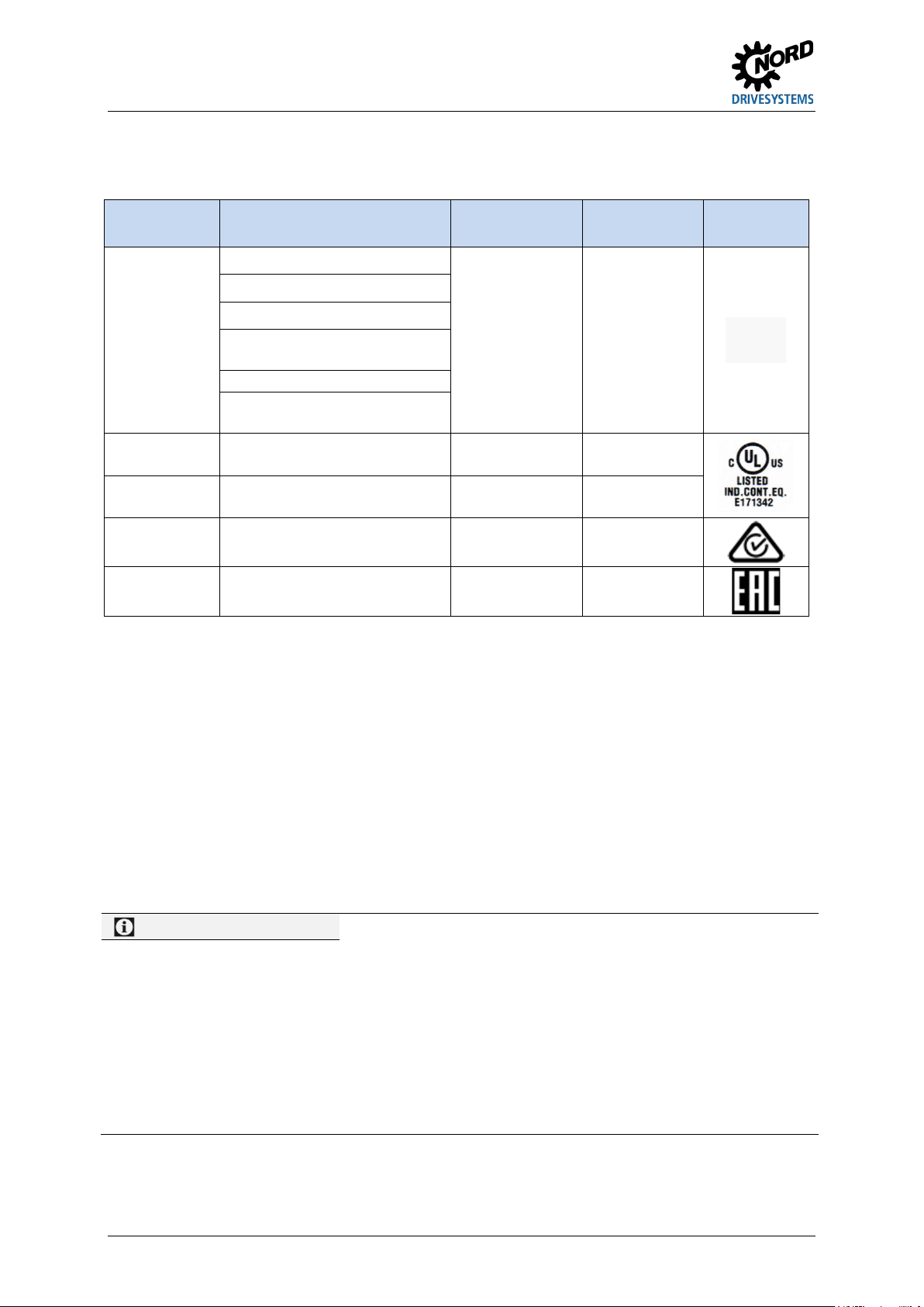
1.7 Standards and approvals .................................................................................................................18
1.7.1 UL and CSA approval.........................................................................................................18
1.8 Type code / nomenclature................................................................................................................20
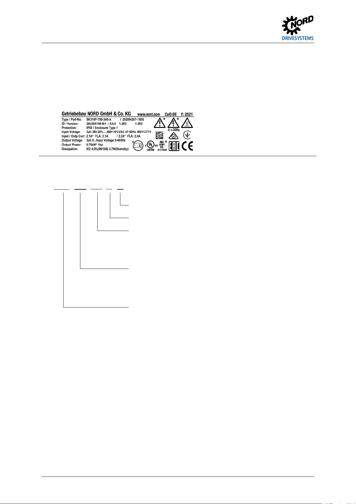
1.8.1 Name plate .........................................................................................................................20
2Assembly and installation ........................................................................................................................21
2.1 Installation........................................................................................................................................21
2.2 Dimensions NORDAC ON, motor-mounted .....................................................................................22
2.3 Dimensions NORDAC ON+, motor-mounted ...................................................................................23
2.4 Dimensions NORDAC ON and NORDAC ON+, wall-mounted ........................................................24
2.5 Connections .....................................................................................................................................25
2.5.1 NORDAC ON motor-mounted, Size 1 ................................................................................25
2.5.2 NORDAC ON motor-mounted, Size 2 ................................................................................26
2.5.3 NORDAC ON+ motor-mounted, Size 2 ..............................................................................27
2.5.4 NORDAC ON wall-mounted, Size 1 ...................................................................................28
2.5.5 NORDAC ON and NORDAC ON+, wall-mounted, Size 2...................................................29
2.6 Electrical Connection .......................................................................................................................30
2.6.1 Mains connection................................................................................................................30
2.6.2 Daisy chain connection.......................................................................................................30
2.6.3 Motor connection ................................................................................................................31
2.6.4 Wiring guidelines ................................................................................................................32
2.6.5 Electrical connection of power unit .....................................................................................33
2.6.5.1 Mains connection 33
2.6.5.2 Motor cable 34
2.6.5.3 Braking resistor (optionally with size 2 and above) 34
2.6.5.4 Electromechanical brake (optionally with size 2 and above)) 34
2.6.6 Electrical connection Ethernet communication and digital input/outputs ............................36
2.6.6.1 Control connection details 38
2.7 Diagnostic connection......................................................................................................................39
2.8 Encoder............................................................................................................................................40
3Display .......................................................................................................................................................43
3.1 LEDs ................................................................................................................................................43
3.1.1 Display of M1 and M2 when using EtherCAT.....................................................................43
3.1.2 Display of M1 and M2 when using EthernetIP....................................................................44
3.1.3 Display of M1 and M2 when using PROFINET...................................................................45
3.1.4 Display M3..........................................................................................................................45
3.1.5 Display of M4 and M5.........................................................................................................46
3.2 Diagnostic LED ................................................................................................................................46
4Commissioning .........................................................................................................................................47
4.1 Starting up the device ......................................................................................................................47
4.2 Selecting the operating mode for motor control ...............................................................................48
4.2.1 Explanation of the operating modes (P300) .......................................................................48
4.2.2 Overview of controller parameter settings ..........................................................................50
4.2.3 Motor control commissioning steps ....................................................................................51
5Parameter...................................................................................................................................................52
5.1 Parameter overview .........................................................................................................................55