E/R/A2
SYS
AIL1
MODE
AIL2
RUD
AIL1
ELE
FC120
3-axis Flight Control
AIL ELE RUD
NRNR N R
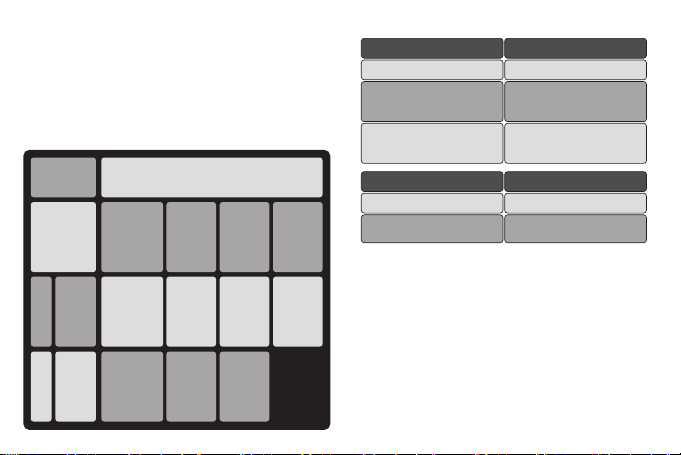
Packing List
● Mini dimension, MEMS gyroscope and accelerometer in one
chip, only 8 grams
● 32-bit high performance ARM MCU
● Original advanced flight control algorithm
● Support single/double aileron, fly wing and V-tail aircraft
● Support flaperon mixing
● Support aerobatic/3D airplanes
● Independent sensitivity adjustment of all 3 axes
● Support Futaba S. BUS protocol
● Gyro can be turned off
● Program via button and LEDs
● Support HV inputs
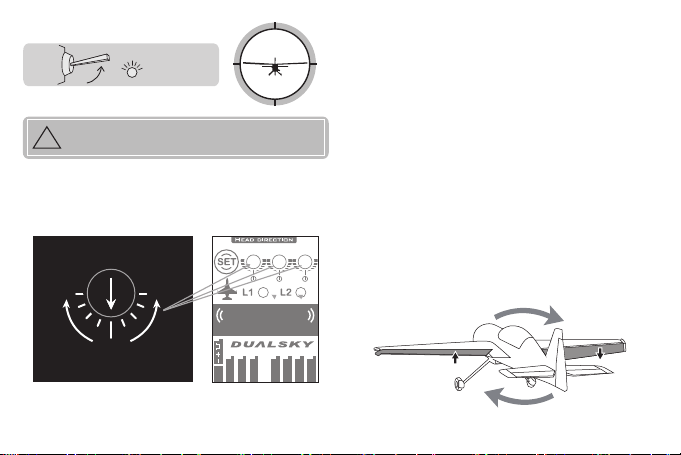
Caution: FC120 will take over all control channels
except throttle, if the setting of FC120 is
inappropriate, it might cause property damage or
personal injury. Please read the caution items and
the rest of this manual carefully before using FC120.
● Recommended to use this gyro on electric powered airplane
models or unpowered glider models
● FC120 need 2~3 sec start-up time after powered on, please
keep the airplane still during the process
● Servos will only work after the FC120 start-up process ends,
this is normal.
You need an at least 4-channel transmitter. If transmitter only
has 4 channels, FC120 will work in aerobatic mode by default
and can’t be turned off during flight. We recommend you for 5
channel transmitter so that the 5th channel (usually the GEAR
channel) can be used for turning off the gyro.
(c)
(a)
(d)
(b)
21021-1
Double
Side
Tape
(a)
FC120 Gyro x 1
(b)
Anti-shock double side tape x 1
(c)
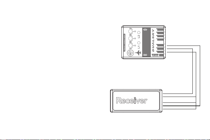
3-signal wire (long) x 1
(d)
Single-signal wire (long) x 2
Radio equipment
- 2 -- 1 -
Thank you for using Dualsky FC120 Flight Control
System. This gyro is equipped with latest MEMS
gyroscope, 32-bit MCU and Dualsky original
algorithm. It features at mini dimensions, high
sensitivity and friendly user interface, more features
are listed below: