7
ENGLISH
L2000631 Installation guide for DucoBox Focus (Revision L | 06.09.2022)
04.B Pairing the control valves
The control valves are paired automatically to the DucoBox whenever ‘installer mode’ is activated (see “Pairing components”
chapter).
04.C Removing / replacing control valves
Taking control valve out temporarily
Follow these steps to take a control valve out of the unit tem-
porarily, e.g. to clean it during maintenance. Make sure that it
is inserted back in the same location. Use the letter labels on
the DucoBox and the relevant valve for this. The DucoBox will
retain all its settings when the control valve is reconnected.
Temporarily removing control valve
1Briefly press the button on the valve to close it
for 15 minutes. The LED will go out.
2Disconnect the wiring.
3Slide the valve out of the DucoBox.
Permanently removing or replacing control valve
To remove a control valve permanently from the system or to replace it (e.g. in the event of a fault) it is important that it should be
deregistered correctly. The DucoBox will not be able to be calibrated correctly if this is not done.
Permanently removing control valve
1Briefly press the button on the valve to drive it shut.
2
Activate ‘Installer mode’ by pressing ‘INST’ on the
DucoBox. The LEDs on the DucoBox and control
valves will flash green rapidly.
3
Long-press the button once on the control valve to
be removed in order to remove it from the network.
ATTENTION: any underlying components will also
be removed from the network.
4Disconnect the wiring from the control valve to be
removed and slide it out of the DucoBox.
5Deactivate ‘Installer mode’ by pressing ‘INST’ on the
DucoBox. All LEDs will stop flashing.
Replacing a control valve
1Briefly press the button on the valve to drive it shut.
2
Activate ‘Installer mode’ by pressing ‘INST’ on the
DucoBox. The LEDs on the DucoBox and control
valves will flash green rapidly.
3Short-press the button twice on the control valve to
be replaced in order to remove it from the network.
4Disconnect the wiring from the control valve to be
replaced and slide it out of the DucoBox.
5Slide the new control valve into the DucoBox and
connect it.
6
Short-press the button on the new control valve
once. The latter will take on all settings / connec-
tions in the network.
7Deactivate ‘Installer mode’ by pressing ‘INST’ on the
DucoBox. All LEDs will stop flashing.
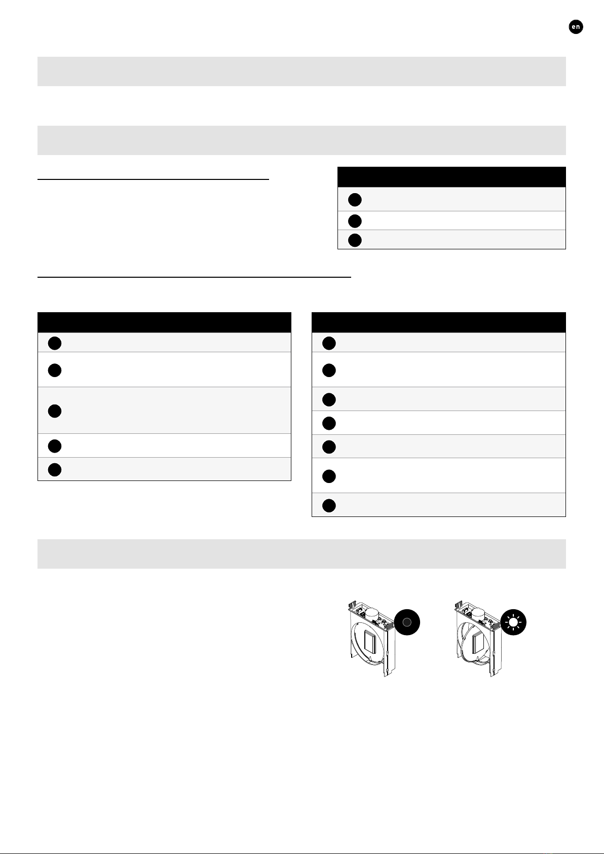
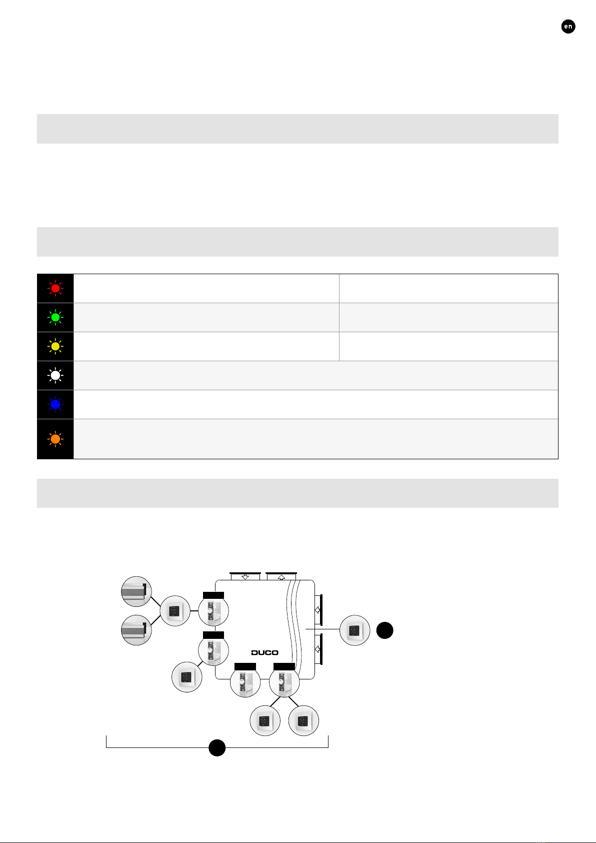
04.D LED indications
In normal operation, the LED on the control valves will be white
or off, depending on the control valve position. The brightness
of the LED indicates the flow rate through the valve.
Please refer to “06.B LED indications on page 9 for the
meaning of the remaining LED colours.
Valve open
= max air flow
LED
Valve shut
= lowest air flow
LED