[page 8] | gpelectric.com
Solar controllers, or solar charge controllers, continuously monitors the solar panel’s generating power and tracks the highest
voltage and current values (VI) in real time, enabling the system to charge the battery to maximum power. It’s designed to be used
in off-grid solar photovoltaic systems to coordinate operation of the solar panel, battery, and load, functioning as the core control
unit in off-grid photovoltaic systems.
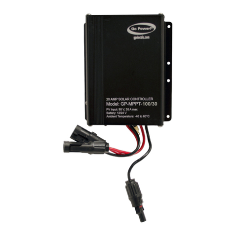
The GP-MPPT-60-10 solar charge controller adopts to the advanced Maximum Power Point Tracking charging methods, enabling
the system charging and discharging management to obtain the most radical optimization. Increase the system exibility, yet lower
down the system cost. The controller supports a variety of batteries, such as sealed, gel, ooded and lithium battery. User can view
and modify the working status and parameters. The features are listed below:
• Advanced multi-peak tracking technology. When the solar panel is shadowed or part of the panel fails resulting in multiple peaks
on the I-V curve, the controller is still able to accurately track the maximum power point.
•
Built-in maximum power point tracking (MPPT) algorithm signicantly increases energy utilization efciency of the photovoltaic
system, (about 15% to 20% higher than traditional PWM charging.)
• MPPT tracking allows up to 99.9% efciency.
• Uses advanced digital power technology to increase the circuit energy conversion efciency to as high as 98%.
• Supports multple battery chemistries, including lithium, sealed, vented, AGM, and ooded Lead Acid.
• Current-limited charging mode. When the power of solar panel is too large and the charging current is higher than the rated value,
the controller automatically reduces the charging power so that the solar panel can operate at the rated charging current.
• Supports automatic identication of lead-acid battery voltage.
• Features LED indicators
•
Built-in over-temperature protection ensures that when temperature exceeds the set value of the device, the charging current decreases
linearly with the temperature, which reduces an increase in the controller’s temperature, avoiding damage.
• Temperature compensation and automatic adjustment of charge and discharge parameters help to improve battery life.
• Solar panel short circuit protection, battery open circuit protection and TVS transient protection.
• IP67 (waterproof) rated. Features a RS485 connection and aluminum housing
4. FEATURES
1. If the temperature sensor is short-circuited or damaged, the controller will be charging or discharging at the default temperature 25 ºC.
2. The port can provide the DC power supply of 5VDC/150mA and have the short circuit function.
When the RS485 communication port is not in use, the waterproof cap must be installed to prevent water ingress and damge to the
controller.
GP-MPPT-60/10
Solar Charge Controller
Quick Start Guide
1
5
2
6
3
4
Read all of the instructions in the manual before installation.
DO NOT disassemble or attempt to repair the controller.
Warnings
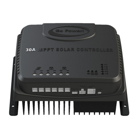
Temperature Sensor PV Positive and
Negative Wires
Battery Positive and
Negative Wires
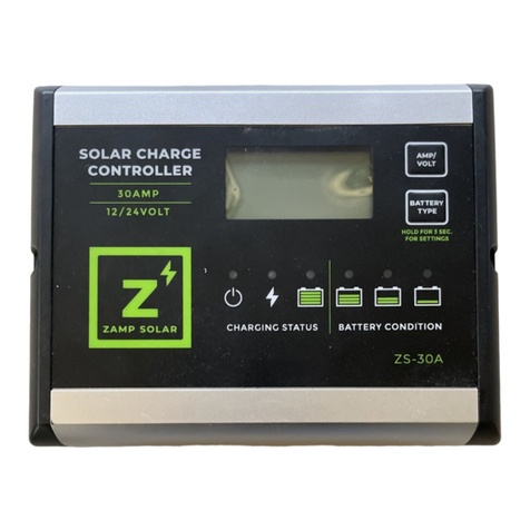
Charging Status
LED indicator
Battery Status
LED indicator
RS485 waterproof port
(Waterproof cap included)
3
6
5
2
4
1
Install external fuse or breaker as required.
Do disconnect the solar module and fuse/ breakers near to battery before
installing or moving the controller.
Power connections must remain tight to avoid excessive heating from
a loose connection.
Only charge batteries that comply with the parameters of controller.
Battery connection may be wired to one battery or a bank of batteries.
Risk of electric shock, the PV and load can produce high voltages when
the controller is working.
Controller Specications
SPECIFICATIONS
Nominal System Voltage 12/24VDC Auto (N/A to Lithium)
Max Solar Array Current 10A
Rated Charge Power 130W/12V | 260W/24V
Max. PV open circuit
voltage
100V (at min operating temperature)
92V (at 250C temperature)
Operating Consumption
Battery Type
MPP Voltage Range
Temp. Compensation
Coefcient
Operating Temperature - 40 to 140ºF / - 40 to 60ºC
4.88 x 3.5 x 1.18 in; 124 x 89 x 30 mm
19.04 oz; 540 g
Dimensions (H x W x D):
Weight
Maximum Wire Gauge: #14 AWG
Warranty 5 years
Protection IP67
Communication RS485
≤13mA/12V;≤11.5mA/24V
-3mV/0C /2V (N/A to Lithium)
Sealed(Default) / Gel / Flooded/User;
LiFePO4/ Li-NiCoMn/User
(Battery voltage+2V)~72V
See user manual for complete instructions at gpelectric.com/MPPT-60-10
3. OVERVIEW
NOTE
