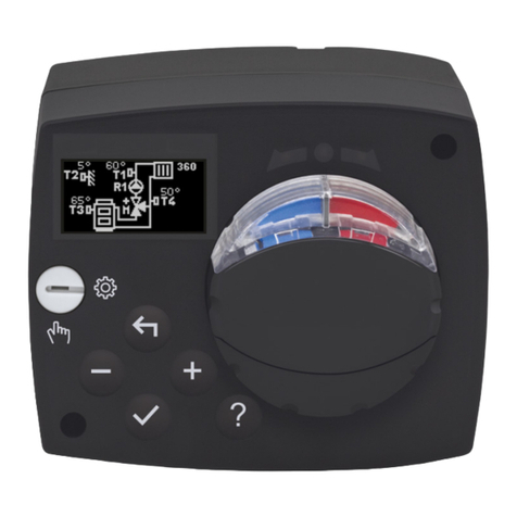
Seltron ACD20 User manual

ACD20
Constant temperature controller
ENEN


| 3
EN
CONSTANT TEMPERATURE
CONTROLLER ACD20
INTRODUCTION
ACD20 controllers are modern microprocessor-controlled devices with an integrated
actuator for the mixing valve and circulation pump control. They are produced in
digital and SMT technology. They are designed to control constant temperature in
various heating and cooling applications. They are most commonly used for the
control of the return temperature to the boiler or the supply temperature to the system.

4 |
EN

| 5
EN
CONTENTS
Introduction .....................................................................................................................................................3
Appearance of the controller....................................................................................................................6
Initial controller setup..................................................................................................................................7
Basic screens .................................................................................................................................................. 11
Help ...................................................................................................................................................................14
Entering and navigating through the menu .....................................................................................14
Menu structure and description............................................................................................................ 15
Requested temperatures......................................................................................................................... 16
Operation mode ........................................................................................................................................... 18
Information....................................................................................................................................................20
Display............................................................................................................................................................. 23
Statistics........................................................................................................................................................ 26
User P parameters..................................................................................................................................... 28
Service S parameters ................................................................................................................................. 31
Factory settings ..........................................................................................................................................38
Clutch and manual valve displacement ............................................................................................39
Controller installation............................................................................................................................... 40
Controller power connection................................................................................................................. 42
Operation modes with sensor failure..................................................................................................43
AUX function at COM input....................................................................................................................44
Technical data..............................................................................................................................................45
Hydraulic schemes .....................................................................................................................................46

6 | Instructions for use
EN APPEARANCE OF THE
CONTROLLER
1. Button . Return back.
2. Button . Move to the left, decreasing.
3. Button . Move to the right, increasing.
4. Button . Menu entry, confirmation of selection.
5. USB port for software updates and connection to a personal computer.
6. Graphic display.
7. Button . Help.
8. Manual operation clutch.
9. Manual movement button.
10. Pre-wired power cord with plug.
11. Pre-wired cable for circulation pump.
12. Pre-wired connection box for sensors and communication.
911128
7
6
1 2 103 4 5

| 7Instructions for use
EN
Use the buttons and to select the requested
language. Confirm the selected language by pressing .
If you've mistakenly selected the wrong language, you
can return to the language selection with the button.
STEP 1 - LANGUAGE SELECTION
INITIAL CONTROLLER SETUP
The controller is equipped with an innovative "Easy start" function, which allows the
initial setting of the controller in just a few steps.
Upon the first connection of the controller to the power supply network, the first step
of the controller setup is displayed after the program version and logo
The manual movement button must be removed for the setup. The Easy start function
is activated by pressing the buttons and and holding them both down together
for 5 seconds.
Later, you can change the language in the
“Display” menu.

8 | Instructions for use
EN
STEP 4: SELECTING THE OPENING DIRECTION OF THE MIXING
VALVE.
You can select the opening direction of the mixing
valve. Use the buttons and to navigate between
directions. Confirm the selected direction with the
button.
If you have mistakenly selected the wrong direction, you
can return to the direction selection with the button.
STEP 2 - SELECTING HEATING OR COOLING OPERATION
Use the buttons and to select the requested
operating mode - heating or cooling.
Confirm the selected operating mode by pressing .
If you've mistakenly selected the wrong operating mode,
you can return to the operating selection with the button
.
STEP 3: HYDRAULIC SCHEME SETUP.
You can select the hydraulic scheme for the controller
operation. Use the buttons and to navigate
between schemes.
Confirm the selected scheme with the button.
If you have mistakenly selected the wrong scheme, you
can return to the diagram selection with the button .
INITIAL CONTROLLER SETUP
Later, you can change the operating mode in the
"Operating mode" menu.
Later, you can change the hydraulic scheme with
the S1.1 service parameter.
Later, you can change the opening direction of the
mixing valve with the service parameter S1.3.

| 9Instructions for use
EN
STEP 6: SETTING THE UPPER LIMIT FOR THE REQUESTED
HEATING TEMPERATURE
With the buttons and you can set up the upper
limit of the requested temperature in heating mode.
Confirm the setup by pressing .
If you have accidentally set the wrong upper limit, you can
return to the upper limit setting by pressing .
STEP 7: SETTING THE REQUESTED HEATING TEMPERATURE
With the buttons and you can set up the requested
temp. in heating mode. Confirm the setup by pressing .
If you have accidentally set the wrong requested
temperature, you can return to the requested temperature
setting by pressing .
For schemes with stand-pipe control, the supply temperature symbol
is displayed.
STEP 5: SETTING THE LOWER LIMIT FOR THE REQUESTED
HEATING TEMPERATURE
With the buttons and you can set up the lower
limit of the requested temperature in heating mode.
Confirm the setup by pressing .
If you have accidentally set the wrong lower limit, you
can return to the lower limit setting by pressing .
INITIAL CONTROLLER SETUP
Later, you can change the lower limit setting of the
requested heating temperature with the service
parameter S2.1.
Later, you can change the upper limit setting of the
requested heating temperature with the service
parameter S2.2.
Later, you can change the requested heating
temperature in the "Requested temperatures"
menu.

10 | Instructions for use
EN
STEP 8: SETTING THE LOWER LIMIT FOR THE REQUESTED
COOLING TEMPERATURE
With the buttons and you can set up the lower
limit of the requested temperature in cooling mode.
Confirm the setup by pressing .
If you have accidentally set the wrong lower limit,
you can return to the lower limit setting by pressing .
STEP 9: SETTING THE UPPER LIMIT FOR THE REQUESTED
COOLING TEMPERATURE
With the buttons and you can set up the upper
limit of the requested temperature in cooling mode.
Confirm the setup by pressing .
If you have accidentally set the wrong upper limit, you
can return to the upper limit setting by pressing .
STEP 10: SETTING THE REQUESTED COOLING TEMPERATURE
With the buttons and you can set up the
requested temperature in heating mode.
Confirm the setup by pressing .
If you have accidentally set the wrong requested
temperature, you can return to the requested
temperature setting by pressing .
For schemes with stand-pipe control, the supply temperature symbol
is displayed.
INITIAL CONTROLLER SETUP
Later, you can change the lower limit setting of the
requested cooling temperature with the service
parameter S2.3.
Later, you can change the upper limit setting of
the requested cooling temperature with the service
parameter S2.4.
Later, you can change the requested cooling
temperature can be later changed in the
"Requested temperatures" menu.

| 11Instructions for use
EN
BASIC SCREENS
All important data on the operation of the controller can be seen in the eight basic
screens. Use the buttons and to navigate between the basic screens.
Status bar
STATUS BAR
Operating mode, notifications and alerts appear in the top third of the screen.
Symbol Description
Room heating.
Room cooling.
Manual operation mode.
Switch o.
Circulation pump is working.
Turn the valve to the left.
Turn the valve to the right.
Manual intervention - the clutch is activated.
AUX function at COM input

12 | Instructions for use
EN BASIC SCREENS
SYMBOLS FOR THE DISPLAY OF TEMP. AND OTHER DATA
TEMPERATURES
Measured
temperature
Requested or
calculated temperature
Symbol Description
Message
In the event that the maximum temperature is exceeded or the safety
function is activated, the controller notifies you with a yellow symbol on
the display. When the maximum temperature is no longer exceeded or
when a protection function has switched o, a gray simbol will turn on
to note the recent event. The list of alerts can be viewed in the
"Information" menu.
Error
In the event of a sensor or communication connection failure, the
controller informs you of the error with a red symbol on the display. If
the error is corrected or is no longer present, a gray symbol indicates a
recent event. The list of errors can be viewed in the "Information" menu.
Symbol Description
Calculated or requested temperature.
Return-pipe temperature.
Inlet temperature.
Source temperature.
T1, T2, ... Temperature sensors T1, T2.
The number of temperatures displayed on the screen depends on the selected
hydraulic scheme and controller settings.

| 13Instructions for use
EN
BASIC SCREENS
HYDRAULIC SCHEME
Hydraulic scheme
with screen
showing the
measured
temperatures
The screen shows the selected hydraulic scheme with the display of measured
temperatures.
TIME AND DATE
MON
Time and date
The screen shows the day of the week, the current time and date.

14 | Instructions for use
EN
ENTERING AND NAVIGATING
THROUGH THE MENU
Press the button to enter the menu.
Navigate through the menu with the and buttons and use the button to
confirm your selection. Press the button to return to the previous screen.
Requested
temperatures
HELP
By pressing the button we can start the display animation, which leads us to the
additional settings menu.

| 15Instructions for use
EN
MENU STRUCTURE
AND DESCRIPTION
Requested
temperatures Operation mode Information
Display
Statistics P parameters
S parameters
Factory settings
The menu consists of eight main groups:

16 | Instructions for use
EN
Requested
temperatures
REQUESTED TEMPERATURES
In the menu, you can change the setting of the requested temperatures according to
the selected hydraulic scheme.
Navigate through the menu with the and buttons and use the button to
confirm your selection. A new screen with temperatures will open.
REQUESTED RETURN-PIPE TEMPERATURE
Use the buttons and to select the requested temperature and confirm it with
the button. Exit the setting by pressing .
Default value
Setting range
Current value of
settings
Current value of the requested temperature
Requested return-
pipe temperature.

| 17Instructions for use
EN
REQUESTED TEMPERATURES
We can only set a temperature value that is available for the selected scheme.
REQUESTED STAND-PIPE TEMPERATURE
Use the buttons and to select the requested temperature and confirm it with the
button. Exit the setting by pressing .
Default value
Setting range
Curent value of
settings
Current value of the requested temperature
Requested stand-
pipe temperature

18 | Instructions for use
EN
TURN OPERATION ON/OFF
Off
On
Turn operation o
Turn operation on
Operation mode
selection
Use the and buttons to select the requested operation and confirm it by
pressing . Exit the setting by pressing .
In the menu, turn the operation on or o.
Navigate through the menu with the and buttons and use the button to
confirm your selection.
In the menu, you can select the requested operation mode and other operation
options.
Heating /
cooling
Dnevna
temperatura
Manual
Operation
Operation mode
OPERATION MODE

| 19Instructions for use
EN
OPERATION MODE
SELECTING HEATING OR COOLING OPERATION
Heating /cooling
symbol
Heating is active Cooling is active
You can select heating or cooling with the and buttons and confirm it with the
button. Exit the setting by pressing .
In the menu, select the requested heating or cooling operation mode.
Heating / cooling
selection
MANUAL OPERATION MODE
Control output
status
Manual operation
mode symbol
Measured
temperature
This operation mode is used when testing the heating system or in the event of a
malfunction. The control output can be manually switched on, switched o or
automatic operation can be selected.
With the buttons and you can move between the individual outputs R1, M- or M
+, and with the button you can select the AUTO, OFF or ON status. Exit the setting
by pressing .

20 | Instructions for use
EN INFORMATION
Navigate through the menu with the and buttons and use the button to
confirm your selection.
The menu is used to display information about the controller, notifications and errors.
Errors
About controller
Messages
Delete
Information
ACD20
Ver.:1.0r0 Sn: 12345678
Type of controller
Serial number
Exit the screen with the button.
ABOUT THE CONTROLLER
Company Logo
Program version
The basic information about the controller is displayed on the screen.
Table of contents
Other Seltron Controllers manuals
