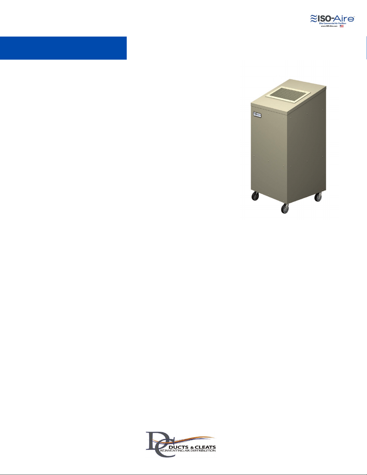
Ducts and Cleats ISO-Aire RSF250 User manual

Operation and Maintenance Manual
Manufacturer Address:
Ducts and Cleats
200 W. Plato Blvd.
St. Paul, MN 55107
Phone: 651-265-0600
Email: [email protected]

handle
Only plug the unit into a grounded outlet. Unit must be electrically grounded. Insert 3-prong plug on power cord directly
into matching grounded receptacle. Do not use with an adapter.
Keep wiring and motor dry. Never use a water hose or pressure washer to clean electrical components; water could
enter the electrical compartment causing a shock hazard. Do not operate in standing water. To reduce risk of personal
injury and electric shock, it should not be played with nor exposed to water or rain.
Turn off power and unplug the unit before changing filters or any maintenance.
Tipping Hazard. Do not stack units on top of each other. Falling equipment could cause bodily harm. Unit must be on a
smooth and solid surface.
Take precautions when handling used filters and disposing of them properly especially if they have been used in a bio-
hazard capacity.
These instructions are intended to help, but do not supersede, code requirements or industry standards.
Read and understand the manual before operating ISO-Aire equipment.
A Note About Safety
Page 2
Wear NIOSH-approved protective gear when changing the HEPA filter as it may contain mold spores
Change the HEPA filter and pre-filter after every remediation job
Dispose of used HEPA according to local regulations
Contamination hazard
If unit is used in hazardous or potentially hazardous environments such as mold mitigation job sites:
Intended Use:
The ISO-Aire commercial air purifier is intended for the use of cleaning and filtering indoor air for commercial or residential
applications.
Moving and Carrying Instructions:
Caution should be used when moving ISO-Aire units to prevent bodily harm and injury. Units with wheels should be slowly
rolled to their desired location; for units without wheels, proper equipment and lifting safety should be followed.
Disconnection Instructions:
Turn the power switch to the OFF position, then unplug the unit from the wall electrical outlet.
A Note About Safety:
Any time you see this symbol in manuals, instructions, and on the unit, be aware of the potential for personal injury.
There are three levels of precaution:
DANGER identifies the most serious hazards which will result in severe personal injury or death.
WARNING signifies hazards that could result in personal injury or death.
CAUTION is used to identify unsafe practices which would result in minor personal injury or product and
property damage.
NOTE is used to highlight suggestions which will result in enhanced installation, reliability, or operation.
HAZARD
Do not look at the UVC light. UVC light can be dangerous to your eyes and skin if not taken seriously. Be sure to turn off
the unit and UVC light before performing maintenance.

handle
A Note About Safety
Page 3
WARNING
PORTABLE UNIT AND METAL SHARP EDGES
HAZARD
Failure to follow this warning could cause personal
injury or death.
This unit must be used in a location where
unsupervised children are not allowed to play. The unit
is portable, and areas inside and under the unit could
cause personal injury.
WARNING
PERSONAL PROTECTION
This appliance is not intended for use by persons
(including children) with reduced physical, sensory, or
mental capabilities, or lack of experience and
knowledge, unless they have been given supervision or
instruction concerning use of the appliance by a person
responsible for their safety.
WARNING
Make sure the path is free of obstacles.
Make sure the wheels are unlocked.
Place hands around the center of the unit and move
slowly.
TIP OVER HAZARD
Failure to follow this warning could result in personal
injury and/or property damage.
Unit must be on a smooth and solid surface. When
moving the unit:
WARNING
Do not place objects on top of the discharge plenum.
Keep hands and face away.
Rotating blower wheel can cause serious injury.
Wear gloves when handling.
MOVING PARTS AND SHARP EDGES HAZARD
Failure to follow this warning could result in personal
injury.
WARNING
ELECTRICAL SHOCK HAZARD
Failure to follow this warning could result in personal
injury or death.
Disconnect all electrical power to the unit before
removing access panels to perform any maintenance.
If the supply cord is damaged, it must be replaced by
the manufacturer, its service agent, or similarly qualified
persons in order to avoid a hazard.
WARNING
PERSONAL INJURY OR PROPERTY DAMAGE
HAZARD
Failure to follow this warning could result in personal
injury or property damage.
Improper installation, adjustment, alteration, service,
maintenance, or use can cause conditions which may
cause personal injury or property damage. Consult a
qualified installer or your distributor for information or
assistance. Read and follow all instructions and
warnings, including labels shipped with or attached to
unit before operating.
WARNING

handle
Une note sur la sécurité
Page 4
WARNING
UNITÉ PORTABLE ET RISQUE DE BORDS
TRANCHANTS EN MÉTAL
Le non-respect de cet avertissement peut entraîner des
blessures corporelles ou la mort.
Cet appareil doit être utilisé dans un endroit où les enfants
sans surveillance ne sont pas autorisés à jouer. L'unité est
portable et les zones à l'intérieur et sous l'unité peuvent causer
des blessures.
PROTECTION PERSONNELLE
Cet appareil n'est pas destiné à être utilisé par des
personnes (y compris des enfants) ayant des capacités
physiques, sensorielles ou mentales réduites, ou un
manque d'expérience et de connaissances, à moins qu'elles
n'aient reçu une supervision ou des instructions concernant
l'utilisation de l'appareil par une personne responsable de
leur sécurité.
Assurez-vous que le chemin est libre d'obstacles.
Assurez-vous que les roues sont déverrouillées.
Placez les mains autour du centre de l'appareil et
déplacez-vous lentement.
RISQUE DE BASCULEMENT
Le non-respect de cet avertissement peut entraîner des
blessures et/ou des dommages matériels.
L'unité doit être sur une surface lisse et solide. Lors du
déplacement de l'unité : Ne placez pas d'objets au-dessus du plénum de
décharge.
Gardez les mains et le visage éloignés.
La roue de soufflante en rotation peut causer des
blessures graves.
Portez des gants lors de la manipulation.
RISQUE DE PIÈCES EN MOUVEMENT ET DE
BORDS TRANCHANTS
Le non-respect de cet avertissement peut entraîner des
blessures.
RISQUE DE CHOC ÉLECTRIQUE
Le non-respect de cet avertissement peut entraîner des
blessures corporelles ou la mort.
Débranchez toute l'alimentation électrique de l'unité avant
de retirer les panneaux d'accès pour effectuer tout
entretien.
Si le cordon d'alimentation est endommagé, il doit être
remplacé par le fabricant, son agent de service ou des
personnes de qualification similaire afin d'éviter tout
danger.
AVERTISSEMEMT
RISQUE DE BLESSURE CORPORELLE OU DE
DOMMAGE MATÉRIEL
Le non-respect de cet avertissement peut entraîner des
blessures ou des dommages matériels.
Une installation, un réglage, une modification, un entretien, une
maintenance ou une utilisation inappropriés peuvent entraîner
des conditions pouvant causer des blessures ou des
dommages matériels. Consultez un installateur qualifié ou votre
distributeur pour obtenir des informations ou de l'aide. Lisez et
suivez toutes les instructions et tous les avertissements, y
compris les étiquettes expédiées avec ou attachées à l'unité
avant de l'utiliser.
AVERTISSEMEMT
AVERTISSEMEMT AVERTISSEMEMT

handle
Thank you for purchasing an ISO-Aire system. ISO-Aire is a family of
commercial air purifiers designed to provide clean air through proven
technology. ISO-Aire is the ideal solution for facilities to protect staff
and customers by adding filtration capability to their facilities.
ISO-Aire utilizes a medical-grade HEPA filter with a combination of
options such as ozone-free bipolar ionization and UVC sterilization.
These air purification technologies are paired with a powerful
commercial-grade fan for a long life and high quality solution. Models
are variable speed and are available from 250 CFM up to 4,000 CFM
designs. In addition, units can be floor set, hung, window mounted
and even outdoor mounted depending on application needs and
model chosen.
For additional information about ISO-Aire clean air technology, visit
our website at www.ISO-Aire.com. And we feature several helpful
tutorials and informational videos on our YouTube channel.
ISO-Aire
Page 5

handle
Determine desired location for unit (ensure 1-2 ft of space
around the intake for proper airflow);
Adjust grille fins if needed for desired air path;
Plug unit into outlet;
Use the rear access panel to set unit at desired fan speed
% and flip the power switch to on.
Note, the unit may take a minute for the fan to
ramp up and come to the set speed due to a grid-
friendly motor feature.
The ISO-Aire commercial air purifier is easy to install and
plugs into a standard 110 volt outlet. The startup
process is as follows:
1.
2.
3.
4.
We recommend letting the ISO-Aire units run 24/7. This helps
clean the entire building envelope as the existing return air
system in the room will help distribute the cleaned air from
the ISO-Aire to the rest of the facility.
Startup and Install
Page 6

handle
Power Requirements: 115 VAC/Single Phase/60hz
Motor: 1/10 HP
Filtration: HEPA 99.99%, 0.3 μ filter; MERV-8 pre-filter
Fan Full Load Amps: 1.5
Fan Total Static Pressure: 1.0" W.G.
Optional UVC Full Load Amps (RSF300 only): 1.36
Optional Bipolar Ionization Full Load Amps: 0.01
Power Requirements: 115 VAC/Single Phase/60hz
Motor: ¼ HP
Filtration: HEPA 99.99%, 0.3 μ filter; MERV-8 pre-filter
Fan Full Load Amps: 3.9
Fan Total Static Pressure: 1.25" W.G.
Optional UVC Full Load Amps: 1.36
Optional Bipolar Ionization Full Load Amps: 0.41
Power Requirements: 115 VAC/Single Phase/60hz
Motor: ½ HP
Filtration: HEPA 99.99%, 0.3 μ filter; MERV-8 pre-filter
Fan Full Load Amps: 5.9
Fan Total Static Pressure: 1.5" W.G.
Optional UVC Full Load Amps: 1.36
Optional Bipolar Ionization Full Load Amps: 0.41
300 & 400 CFM Models (RSF250, RSF300)
500 CFM Models (RSF500)
750 CFM Models (RSP750, RSF750)
Specifications
Power Requirements and Filtration
Page 7
Power Requirements: 115 VAC/Single Phase/60hz
Motor: 1 HP
Filtration: HEPA 99.9%, 0.3 μ filter; MERV-8 pre-filter
Fan Full Load Amps: 13.6
Fan Total Static Pressure: 1.5" W.G.
Optional UVC Full Load Amps: 1.36
Optional Bipolar Ionization Full Load Amps: 0.41
2,000 CFM Models (RSF2000)
Power Requirements: 115 VAC/Single Phase/60hz
Motor: ½ HP
Filtration: HEPA 99.99%, 0.3 μ filter; MERV-8 pre-filter
Fan Full Load Amps: 5.9
Fan Total Static Pressure: 1.5" W.G.
Optional UVC Full Load Amps: 1.36
Optional Bipolar Ionization Full Load Amps: 0.41
800 CFM & 1,000 CFM Models (RSP1000, RSF1000, RSH800, RSH1000)

handle
Pre-filters should be changed periodically (see below). ISO-Aire extended life pre-filters allow for a
longer service life. Pre-filters are inexpensive but extend the life of the HEPA filter by capturing the
larger particles and contaminants (like dust).
Exact pre-filter life will vary by application and may require more frequent replacement than listed
below.
ISO-Aire uses a MERV-8 pre-filter to extend the life of the HEPA filter. A high capacity, extended-life pre-
filter is available for purchase from ISO-Aire which provides a longer lifespan compared to standard pre-
filters. A standard pre-filter is a common filter that can be purchased from many suppliers or retail stores
(the same kind used in a typical furnace). When ordering a replacement pre-filter, use the sizes below to
purchase from your preferred source to ensure the same design specs for optimal operation. Failure to use
proper filtration will void warranty and could result in damage or decreased performance out of the system.
NOTE: ISO-Aire High Capacity pre-filters provide a longer life vs. Standard Capacity pre-filters.
Pre-Filters
300 CFM Models (RSF250)
Size: 12” x 12" x 1”, MERV-8
High Capacity Pre-Filter Part Number: PREF12121 (change every 3 months) If using a standard capacity pre-filter, change every 2 months.
400 CFM Models (RSF300)
Size: 14” x 16” x 1”, MERV-8
High Capacity Pre-Filter Part Number: PREF14161 (change every 3 months) If using a standard capacity pre-filter, change every 2 months.
500 CFM Models (RSF500)
Size: 18” x 20” x 1”, MERV-8
High Capacity Pre-Filter Part Number: PREF18201 (change every 3 months) If using a standard capacity pre-filter, change every 2 months.
750 CFM Models (RSP750, RSF750)
Size: 20" x 24" x 2", MERV-8
High Capacity Pre-Filter Part Number: PREF20242 (change every 4 months) If using a standard capacity pre-filter, change every 2 months
800 CFM Models (RSH800)
Size: 20" x 20" x 2", MERV-8
High Capacity Pre-Filter Part Number: PREF20202 (change every 4 months) If using a standard capacity pre-filter, change every 2 months
1,000 CFM Models (Gen 2 - Current) (RSF1000, RSP1000)
Size: 20" x 24" x 2", MERV-8
High Capacity Pre-Filter Part Number: PREF20242 (change every 4 months) If using a standard capacity pre-filter, change every 2 months
1,000 CFM Models (Gen 1) (RSF1000)
Size: 24" x 24" x 2", MERV-8
High Capacity Pre-Filter Part Number: PREF24242 (change every 4 months) If using a standard capacity pre-filter, change every 2 months
2,000 CFM Models (RSF2000)
Size: 24" x 24" x 2", MERV-8
High Capacity Pre-Filter Part Number: PREF24242 (change every 4 months) If using a standard capacity pre-filter, change every 2 months
Page 8

handle
Ensure minimum efficiency of 99.99% at .3 microns.
For units with UVC, metal construction of filter housing is required.
The HEPA filters are designed to provide a 3- to 5-year life depending on the building environment.
Clean environments may see longer filter life and dirty environments may see shorter. Pre-filter
maintenance is key to extending the life of the HEPA. If your unit is equipped with a mini-helic
gauge, this will give indication of the filter life by measuring the restriction / total static pressure
resistance (see page 4 for total static pressure capability per model).
ISO-Aire uses a medical-grade and high capacity HEPA filter. When ordering a replacement filter use
the part number below to purchase from the OEM filter the unit came with. Failure to use proper filtration
will void warranty and could result in damage or decreased performance out of the system.
To order replacement HEPA filters, please contact us at 800-701-2513 or email
support@airpurifiersandcleaners.com
HEPA Filters
500 & 800 CFM Models (RSF500, RSH800)
Size: 20” x 20” x 12”
Part Number: HEPA2020
750 CFM Models (RSP750, RSF750)
Size: 20” x 24” x 12”
Part Number: HEPA2024
1,000 CFM Models (Gen 1 & 2,
RSF1000, RSP1000, RSH1000)
Size: 24” x 24” x 12”
Part Number: HEPA2424
Page 9
400 CFM Models (RSF300)
Size: 16” x 16” x 12”
Part Number: HEPA1616
2,000 CFM Models (RSF2000)
Size: 24” x 24” x 6” (two filters)
Part Number: HEPA246
300 CFM Models (RSF250)
Size: 12” x 12” x 12”
Part Number: HEPA1212

handle
Never look at or expose your skin to the ultraviolet lights directly.
Bulbs should replaced yearly (approx. 9,000 service life). The killing power of the bulbs starts to
diminish after 12 months and therefore should be replaced even if not burned out.
For units with UVC, metal construction of HEPA filter housing is required.
110 Volts / .68 amps
Does not produce ozone.
UVC lamps contain a small amount of mercury and should be disposed of according to local laws.
ISO-Aire is available with UVC sterilization which has been carefully designed into our unit to ensure
efficacy and proper exposure / duration to pathogens. The UVC is properly contained within the ISO-Aire
system to prevent exposure to occupants without proper PPE. Anytime the unit is being serviced and is
equipped with UVC, the unit should be turned off and the UVC unplugged. Local codes and proper PPE
should be worn as applicable if service needs to happen with the lights on.
UVC Sterilization (Optional)
Page 10
All Models:
Size: Two dual 16” bulb, 36 watts each
Wavelength: 253.7 nanometers
Bulb Part Number: UVCPH36

handle
UVC Sterilization Installation
Page 11
If you've ordered an ISO-Aire unit equipped with UVC, the bulbs and housing are shipped loose to
prevent damage to the UVC during transit. Installation of the UVC once the unit is in place is easy. This is
the same procedure for installing replacement bulbs.
Be sure to wear the included cloth glove to keep oil from your hands off the bulbs
Insert the bulbs into the housing by inserting sideways (Figure A), twisting so the bulb fits in the
securing tabs (Figure B) and then pushing the bulb into the four pin connection (Figure C)
Slide the metal reflective cover over the entire UVC bulb up to the white base (Figured D), this is to
protect the HEPA filter by shielding it from direct UVC light.
IMPORTANT - install the metal reflective cover so that light shines downward, not upward (see
Figure E).
Install the housing into the UVC plenum (note the housing will only fit one way) (Figure E)
Use the four mounting bolts/nuts to secure the UVC to the unit (Figure F)
Figure A Figure B Figure C
Figure D Figure E Figure F

handle
ISO-Aire uses a UL 2998 listed needle point bipolar ionization device that is ozone-free and available on all
models. Bipolar ionization emits positive and negative ions which helps to neutralize pathogens and causes
them to also agglomerate and fall to the floor. The bipolar ionization is also effective on mold, odors, VOCs,
allergens, and other airborne contaminants. With the strategic mounting of the bipolar ionization device
within the ISO-Aire, this allows for maximum ion concentrations in the space and also for the ideal pairing
with higher filtration from our HEPA filter.
Caution: Never touch the ionizer brushes while operating, shock may occur.
Ozone-Free Bipolar Ionization (Optional)
All Models (except RSF300)
Manufacturer: Global Plasma Solutions
Part Number: GPS-FC48-AC
Ozone free UL2998
Page 12
RSF250 & RSF300
Manufacturer: Plasma Air
Part Number: PA 603
Ozone free UL2998
GPS-FC48 does not require any maintenance
and has an auto-cleaning feature
The PA 603 was designed for low maintenance.
Inspect the ionizer brushes once a year for buildup.
Should cleaning be necessary, use a soft brush or
compressed air. Be sure to turn unit off before
cleaning.

handle
ISO-Aire uses a long-life and high quality, variable speed ECM fan to provide the desired fan speed and
CFM output. The speed controller is located next to the on/off switch and can be adjusted as needed. Use
the tables below based on your model for CFM at various fan speed %. Be sure to check the fan speed
control during initial setup to confirm it is at the desired speed.
Note: the unit may take a minute for the fan to ramp up and come to the set speed due to a grid-friendly
motor feature.
Fan Speed Setting Selection
Page 13
Approximate Airflow

Push the
metal tabs
out to hold
the enclosure
up when
removing the
screws.
Do not
remove
the 5
screws
running
vertical
on the
back side
of the
unit.
RSF250 & RSF300 Series (non UVC equipped)
For RSF250 and RSF300 without UVC, before replacing the HEPA or pre-filter ensure unit is first turned
off. See pages 5 and 6 for filter part numbers, sizes, and service intervals.
To replace the HEPA, first slide out the enclosure resting tabs on the left and right side so that the
enclosure does not fall when the screws are removed in step 2 (See Figure A). Next, release the
enclosure for removal from the inner core by removing the 11 screws along the bottom on each side (3
screws on the front, left and right sides, 2 screws on the back side). Do not remove the screws that run up
vertical along the unit on the backside (see Figure B.) Continued on next page.
Filter Maintenance
Page 14
Remove on
each side of
the unit the
screws
located on the
bottom (11
screws total).
This will allow
for removal of
the enlosure
off of the unit.
Do not remove
the screws
running
vertical up the
side of the
unit.
Figure B Figure A
Power
switch
and speed
control
access
panel.

Filter
brackets (4
total, one on
each side).
Four 7/16 bolts for loosening or tightening
the HEPA filter during replacement (one on
each side of the unit).
Fan and filter
housing
assembly.
Remove the 3
screws on each
side and 2 on the
back to allow
removal of
enclosure for
HEPA access.
RSF250 & RSF300 Series (non UVC equipped), Continued
When all 11 screws have been removed, the enclosure is now ready to be removed. Simply lift straight
up and clear the inner core and set the enclosure off to the side. Now that the inner core is exposed,
remove the lower bolt on each filter bracket (one on each side, 4 total) (See Figure D), then lift the fan
assembly back on the filter. Lift the HEPA out of the unit and replace with the new filter. Then set the fan
assembly back on the filter, tighten each of the filter bracket bolts, and reattach the enclosure. When
putting the enclosure back on, make sure the power cord slides into the cord slot on the enclosure and
does not bind. The enclosure screws only need to be hand tight.
Filter Maintenance
Page 15
Figure B, continued Figure D
Power cord
slot on the
enclosure

Do not
remove the
6 screws
running
vertical on
the back
side of the
main body
of unit, or
the 9
screws on
the intake
plenum.
Remove on
each side
of the unit
the screws
located on
the bottom
(11 screws
total). This
will allow
for
removal of
the
enclosure
off of the
unit.
Do not remove the
screws on the bottom
intake plenum of the unit.
Main Body
Power
switch and
speed
control
access
panel.
Pre-filter
access panel
latch
RSF300 Series (UVC equipped)
For RSF300, before replacing the HEPA or pre-filter, ensure the unit is first turned off. See pages 5 and 6
for filter part numbers, sizes, and service intervals.
To replace the HEPA, release the enclosure for removal from the inner core by removing the 11 screws
along the bottom on each side of the main body (3 screws on the front, left, and right sides; 2 screws on
the back side). (See Figure A and B.) Next, point the two pre-filter panel securing latches downward. Do
not remove the screws that run up vertical along the unit on the backside of the main body or the screws
on the intake plenum (see Figure A and B). Continue on next page.
Filter Maintenance
Page 16
Figure A Figure B
Intake
Plenum

Filter
brackets (4
total, one on
each side).
Four 7/16 bolts for loosening or
tightening the HEPA filter during
replacement (one on each side of
the unit).
Fan and filter
housing
assembly.
Remove the
3 screws on
each side
and 2 on the
back to
allow
removal of
enclosure
for HEPA
access.
RSF300 Series (UVC equipped), Continued
When all 11 screws have been removed, the enclosure is now ready to be removed. Simply lift straight
up and clear the inner core and set the enclosure off to the side. Now that the inner core is exposed,
remove the lower bolt on each filter bracket (one on each side, 4 total) (See Figure D), then lift the fan
assembly off of the filter. Lift the HEPA out of the unit and replace with the new filter. Then set the fan
assembly back on the filter, tighten each of the filter bracket bolts and reattach the enclosure. When
putting the enclosure back on, make sure the power cord slides into the cord slot on the enclosure and
does not bind. The enclosure screws only need to be hand tight.
Filter Maintenance
Page 17
Figure B, continued Figure D
Power cord
slot on the
enclosure

Four 5/16 bolts for loosening or tightening
the HEPA filter during replacement (two on
each side of the unit).
Rear service
panel.
Removal
allows access
to HEPA.
Remove the 12 screws on the rear
service panel to access the HEPA
filter and fan. The four screws
securing the pre-filter access
panel also need to be removed to
take off the entire rear panel.
RSF500 and RSP1000 Series
Before replacing the HEPA or pre-filter ensure unit is first turned off. See pages 5 and 6 for filter part
numbers, sizes, and service intervals.
The HEPA filter is secured using a tensioning mechanism which holds the filter secure in place. To
replace, remove the rear service panel (see Figure A). Then lower the HEPA filter by turning the four
tension adjustment bolts located at the bottom of the unit (see Figure B) counter clockwise until filter is
lowered and can be removed. When installing a new filter do not overtighten. Tighten both bolts evenly
for a good seal on the gasket. Ensure gasket is facing up when installing the HEPA.
Filter Maintenance
Page 18
Figure A Figure B
Power
switch
and speed
control
access
panel.
Pre-filter access panel.

Remove the intake grille on
each side of the unit to access
the HEPA tensioning bolts.
Main rear access
panel, removal
allows access to
the HEPA filter.
Remove the 14
screws on the rear
service panel to
access the HEPA
filter and fan. The
four screws
securing the pre-
filter access panel
also need to be
removed to take
off the entire rear
panel.
RSF1000 Series (Gen 2 - Current) Series
Before replacing the HEPA or pre-filter ensure unit is first turned off. See pages 5 and 6 for filter part
numbers, sizes, and service intervals.
The HEPA filter is secured using a tensioning mechanism which holds the filter secure in place. First,
remove the main rear service panel by removing the 14 screws (see Figure A). Then remove the intake
grille on each side of the unit (see Figure B). Then the tensioning bolts can be accessed. Lower the
HEPA filter by turning the four tension adjustment bolts counter clockwise, be sure to loosen at the
bottom of bolt as shown in Figure C until the filter is lowered and can be removed. When installing a
new filter do not over tighten. Tighten both bolts evenly for a good seal on the gasket. Ensure gasket is
facing up when installing the HEPA.
Filter Maintenance
Page 19
Figure A Figure B
Power switch and
speed control
access panel.
Intake Plenum
Access, do not
remove these
screws.
Four 5/16 bolts for loosening or
tightening the HEPA filter during
replacement can be accessed through
the intake grille openings (two on each
side of the unit).
Figure C

HEPA filter tension adjustment bolts
(use a 9/16 socket)
RSP750, RSF750 CFM, FSF1000 Series (Gen 1, obsolete)
Before opening the access door and changing filters or performing maintenance, be sure to turn off unit.
Replacing the pre-filter or HEPA filter requires removal of the access door. Lift up using the handle and pull
the bottom outwards. See pages 5 and 6 for filter part numbers, filter sizes, and service intervals.
The HEPA filter is secured using a tensioning mechanism which holds the filter secure in place. To replace,
lower the HEPA filter from the frame by turning the two tension adjustment bolts counter clockwise until filter
is lowered and can be removed. When installing a new filter do not overtighten and be sure to tighten both
bolts evenly. Install new HEPA filter with gasket facing up.
Filter Maintenance
Access door handle
Pre-filter
HEPA filter
resides behind a
black removable
magnetic cover
Page 20
This manual suits for next models
9
Table of contents