manuals.online logo
Brands
  1. Home
  2. •
  3. Brands
  4. •
  5. Duerkopp Adler
  6. •
  7. Sewing Machine
  8. •
  9. Duerkopp Adler 4181i User manual

Duerkopp Adler 4181i User manual

Instruction manual
4181i - 3
Minerva Boskovice, a.s., Sokolská 60, CZ - 680 17 Boskovice
Tel.: +420-516-453434, 453433, 494111 Fax: +420-516-452165 http://www.minerva-boskovice.com
Edition/Vydáno/Herausgegeben: 09/2004 Printed/Tisk/Druck: Czech Republic S735 000678
www.promelectroavtomat.ru
Contents - part A - Instruction manual:
1. Proper use of the machine ................................................................................................................................................ 1
2. Machine description .......................................................................................................................................................... 1
3. Machine subclasses and sewing categories ................................................................................................................... 2
3.1 Subclass ................................................................................................................................................................. 2
3.2 Sewing categories ................................................................................................................................................... 2
4. Survey of equipment ........................................................................................................................................................ 2
4.1 Basic necessary equipment .................................................................................................................................... 2
4.1.1 Needles ...................................................................................................................................................... 2
4.1.2 Wheel feeders .............................................................................................................................................................. 2
4.1.3 Top roller holders ......................................................................................................................................................... 2
4.1.4 Top rollers ................................................................................................................................................................... 2
4.1.5 Throat plate ................................................................................................................................................................. 3
4.1.6 Throat plate inserts ..................................................................................................................................................... 3
4.1.7 Trimmer knife .............................................................................................................................................................. 3
4.1.8 Guide ........................................................................................................................................................................... 3
4.1.9 Connecting cables of the head to the drive ............................................................................................................. 3
4.2 Optional eqiupment ................................................................................................................................................ 3
5. Technical data .................................................................................................................................................................. 3
6. Operation of the machine ................................................................................................................................................. 5
6.1 Threading a thread ............................................................................................................................................... 5
6.2 Bobbin thread winding ......................................................................................................................................... 5
6.3 Inserting the bobbin and threading the lower thread ............................................................................................ 5
6.4 Regulating the thread tension .............................................................................................................................. 6
6.5 Needle replacement .............................................................................................................................................. 7
6.6 Regulation of pressing the top roller ..................................................................................................................... 7
6.7 Lifting the top roller up .......................................................................................................................................... 7
6.8 Reverse stitching .................................................................................................................................................. 8
6.9 Stitch length adjustment ....................................................................................................................................... 8
6.10 Safety clutch ........................................................................................................................................................... 8
6.11 To exchange and set the trimmer knife .................................................................................................................. 8
7. Electronic control of the machine ................................................................................................................................... 9
7.1 Control of sewing by means of control elements .................................................................................................. 9
7.1.1 Via treadle ................................................................................................................................................... 9
7.1.2 Via control pushbutton panel ...................................................................................................................... 9
7.1.3 Via control panel V810/V 820 ...................................................................................................................... 9
7.2 Adjustment of automatic functions via control panel for stop motor ................................................................... 10
7.2.1 By using stop motor Efka with panel V 810 ............................................................................................... 10
7.2.1.1 Adjustment by means of buttons with fixed setting function ........................................................ 10
7.2.1.2 Setting by means of parameters ................................................................................................... 11
7.2.2 By using stop motor Efka with panel V 820 ............................................................................................... 12
7.2.2.1 Adjustment by means of buttons with fixed setting function ........................................................ 13
7.2.2.2 Setting by means of parameters ................................................................................................... 13
8. Maintenance ....................................................................................................................................................................................... 14
Operating instructions for eventual trouble shooting .............................................................................................................. 15
www.promelectroavtomat.ru
Foreword
This instruction manual is intended to help the user to become familiar with the machine and take advantage of its application
possibilities in accordance with the recommendations.
The instruction manual contains important information on how to operate the machine securely, properly and economically.
Observation of the instructions eliminates danger, reduces costs for repair and down-times, and increases the reliability and life
of the machine.
The instruction manual is intended to complement existing national accident prevention and environment protection regulations.
The instruction manual must always be available at the machine/sewing unit.
The instruction manual must be read and applied by any person that is authorized to work on the machine/sewing unit. This
means:
- Operation, including equipping, troubleshooting during the work cycle, removing of fabric waste
- Service (maintenance, inspection, repair and/or)
- Transport.
The user also has to assure that only authorized personnel work on the machine.
The user is obliged to check the machine at least once per shift for apparent damages and to immediatly report any changes
(including the performance in service), which impair the safety.
The user company must ensure that the machine is only operated in perfect working order.
Never remove or disable any safety devices.
If safety devices need to be removed for equipping, repairing or maintaining, the safety devices must be remounted directly after
completion of the maintenance and repair work.
Unauthorized modification of the machine rules out liability of the manufacturer for damage resulting from this.
Observe all safety and danger recommendations on the machine/unit! The yellow-and-black striped surfaces designate permanend
danger areas, eg danger of squashing, cutting, shearing or collision.
Besides the recommendations in this instruction manual also observe the general safety and accident prevention regulations!
www.promelectroavtomat.ru
General safety instructions
The non-observance of the following safety instructions can cause bodily injuries or damages to the machine.
1. The machine must only be commissioned of the instruction book and operated by persons with appropriate training.
2. Before putting into service also read the safety rules and instructions of the motor supplier.
3. The machine must be used only for the purpose intended. Use of the machine without the safety devices is not permitted. Observe
all the relevant safety regulations.
4. When gauge parts are exchanged (e.g. needle, presser foot, needle plate, feed dog and bobbin) when tread-ing, when the workplace
is left, and during service work, the machine must be disconnected from the mains by switching off the master switch or disconnecting
the mains plug.
5. Daily servicing work must be carried out only by appropriately trained persons.
6. Repairs, conversion and special maintenance work must only be carried out by technicians or persons with appropriate training.
7. For service or repair work on pneumatic systems the machine must be disconnected from the compressed air supply system.
Exceptions to this are only adjustments and functions checks made by appropriately trained technicians.
8. Work on the electrical equipment must be carried out only by electricians or appropriately trained persons.
9. Work on parts and systems under electric current is not permitted, except as specified in regulations DIN VDE 0105.
10. Conversion or changes to the machine must be authorized by us and made only in adherence to all safety regulations.
11. For repairs, only replacement parts approved by us must be used.
12. Commissioning of the sewing head is prohibited until such time as the entire sewing unit is found to comply with EC directives.
It is absolutely necessary to respect the safety instructions marked by these signs.
Danger of bodily injuries !
Please note also the general safety instructions.
IMPORTANT WARNING!
To the feeding network cord, it is necessary to connect the respective network plug which has been approved in the country
of utilizing the machine. This operation should be performed by a worker acquainted with the electric safety rules being in
force in the given country. The supplier is not responsible for any damages caused by defective plug or owing to incorrect
assembly of the plug.
In spite of all safety measures made on the machines, inappropriate actions of the operator may lead to dangerous situations. In
industrial sewing machines, attention should be paid to the following still remaining possible sources of injury:
1. Moving sewing needle
- risk of injury when sewing with raised pressure foot or top roller, because the finger guard is then positioned too high.
2. Moving thread take-up lever
- risk of injury when inadvertently or intentionally inserting the finger(s) between the thread take-up lever and its guard.
3. Moving pressure member
- risk of injury when holding sewn work in immediate vicinity of the pressure member and beginning to insert under the pressure
member a considerably thicker sewn work portion,
- risk of injury when sinking the pressure member.
4. Moving trimming knife
- risk of injury when sewing and trimming with lifted presser element (roller, foot), because the finger guard is high
- risk of injury when inadvertently threading down of the motor threadle.
5. When switched off, the clutch motor slows down by inertia but would be reactivated by an accidental tread-ing down of the
motor treadle. To avoid such risk, it is advised to hold the handwheel by hand and slightly to depress the motor treadle.
www.promelectroavtomat.ru
Contents - part A - Instruction manual:
1. Proper use of the machine ................................................................................................................................................ 1
2. Machine description .......................................................................................................................................................... 1
3. Machine subclasses and sewing categories ................................................................................................................... 2
3.1 Subclass ................................................................................................................................................................. 2
3.2 Sewing categories ................................................................................................................................................... 2
4. Survey of equipment ........................................................................................................................................................ 2
4.1 Basic necessary equipment .................................................................................................................................... 2
4.1.1 Needles ...................................................................................................................................................... 2
4.1.2 Wheel feeders .............................................................................................................................................................. 2
4.1.3 Top roller holders ......................................................................................................................................................... 2
4.1.4 Top rollers ................................................................................................................................................................... 2
4.1.5 Throat plate ................................................................................................................................................................. 3
4.1.6 Throat plate inserts ..................................................................................................................................................... 3
4.1.7 Trimmer knife .............................................................................................................................................................. 3
4.1.8 Guide ........................................................................................................................................................................... 3
4.1.9 Connecting cables of the head to the drive ............................................................................................................. 3
4.2 Optional eqiupment ................................................................................................................................................ 3
5. Technical data .................................................................................................................................................................. 3
6. Operation of the machine ................................................................................................................................................. 5
6.1 Threading a thread ............................................................................................................................................... 5
6.2 Bobbin thread winding ......................................................................................................................................... 5
6.3 Inserting the bobbin and threading the lower thread ............................................................................................ 5
6.4 Regulating the thread tension .............................................................................................................................. 6
6.5 Needle replacement .............................................................................................................................................. 7
6.6 Regulation of pressing the top roller ..................................................................................................................... 7
6.7 Lifting the top roller up .......................................................................................................................................... 7
6.8 Reverse stitching .................................................................................................................................................. 8
6.9 Stitch length adjustment ....................................................................................................................................... 8
6.10 Safety clutch ........................................................................................................................................................... 8
6.11 To exchange and set the trimmer knife .................................................................................................................. 8
7. Electronic control of the machine ................................................................................................................................... 9
7.1 Control of sewing by means of control elements .................................................................................................. 9
7.1.1 Via treadle ................................................................................................................................................... 9
7.1.2 Via control pushbutton panel ...................................................................................................................... 9
7.1.3 Via control panel V810/V 820 ...................................................................................................................... 9
7.2 Adjustment of automatic functions via control panel for stop motor ................................................................... 10
7.2.1 By using stop motor Efka with panel V 810 ............................................................................................... 10
7.2.1.1 Adjustment by means of buttons with fixed setting function ........................................................ 10
7.2.1.2 Setting by means of parameters ................................................................................................... 11
7.2.2 By using stop motor Efka with panel V 820 ............................................................................................... 12
7.2.2.1 Adjustment by means of buttons with fixed setting function ........................................................ 13
7.2.2.2 Setting by means of parameters ................................................................................................... 13
8. Maintenance ....................................................................................................................................................................................... 14
Operating instructions for eventual trouble shooting .............................................................................................................. 15
www.promelectroavtomat.ru
Foreword
This instruction manual is intended to help the user to become familiar with the machine and take advantage of its application
possibilities in accordance with the recommendations.
The instruction manual contains important information on how to operate the machine securely, properly and economically.
Observation of the instructions eliminates danger, reduces costs for repair and down-times, and increases the reliability and life
of the machine.
The instruction manual is intended to complement existing national accident prevention and environment protection regulations.
The instruction manual must always be available at the machine/sewing unit.
The instruction manual must be read and applied by any person that is authorized to work on the machine/sewing unit. This
means:
- Operation, including equipping, troubleshooting during the work cycle, removing of fabric waste
- Service (maintenance, inspection, repair and/or)
- Transport.
The user also has to assure that only authorized personnel work on the machine.
The user is obliged to check the machine at least once per shift for apparent damages and to immediatly report any changes
(including the performance in service), which impair the safety.
The user company must ensure that the machine is only operated in perfect working order.
Never remove or disable any safety devices.
If safety devices need to be removed for equipping, repairing or maintaining, the safety devices must be remounted directly after
completion of the maintenance and repair work.
Unauthorized modification of the machine rules out liability of the manufacturer for damage resulting from this.
Observe all safety and danger recommendations on the machine/unit! The yellow-and-black striped surfaces designate permanend
danger areas, eg danger of squashing, cutting, shearing or collision.
Besides the recommendations in this instruction manual also observe the general safety and accident prevention regulations!
www.promelectroavtomat.ru
General safety instructions
The non-observance of the following safety instructions can cause bodily injuries or damages to the machine.
1. The machine must only be commissioned of the instruction book and operated by persons with appropriate training.
2. Before putting into service also read the safety rules and instructions of the motor supplier.
3. The machine must be used only for the purpose intended. Use of the machine without the safety devices is not permitted. Observe
all the relevant safety regulations.
4. When gauge parts are exchanged (e.g. needle, presser foot, needle plate, feed dog and bobbin) when tread-ing, when the workplace
is left, and during service work, the machine must be disconnected from the mains by switching off the master switch or disconnecting
the mains plug.
5. Daily servicing work must be carried out only by appropriately trained persons.
6. Repairs, conversion and special maintenance work must only be carried out by technicians or persons with appropriate training.
7. For service or repair work on pneumatic systems the machine must be disconnected from the compressed air supply system.
Exceptions to this are only adjustments and functions checks made by appropriately trained technicians.
8. Work on the electrical equipment must be carried out only by electricians or appropriately trained persons.
9. Work on parts and systems under electric current is not permitted, except as specified in regulations DIN VDE 0105.
10. Conversion or changes to the machine must be authorized by us and made only in adherence to all safety regulations.
11. For repairs, only replacement parts approved by us must be used.
12. Commissioning of the sewing head is prohibited until such time as the entire sewing unit is found to comply with EC directives.
It is absolutely necessary to respect the safety instructions marked by these signs.
Danger of bodily injuries !
Please note also the general safety instructions.
IMPORTANT WARNING!
In spite of all safety measures made on the machines, inappropriate actions of the operator may lead to dangerous situations. In industrial
sewing machines, attention should be paid to the following still remaining possible sources of injury:
1. Moving sewing needle
- risk of injury when sewing with raised pressure foot or top roller, because the finger guard is then positioned too high.
2. Moving thread take-up lever
- risk of injury when inadvertently or intentionally inserting the finger(s) between the thread take-up lever and its guard.
3. Moving pressure member
- risk of injury when holding sewn work in immediate vicinity of the pressure member and beginning to insert under the pressure
member a considerably thicker sewn work portion,
- risk of injury when sinking the pressure member.
4. When switched off, the clutch motor slows down by inertia but would be reactivated by an accidental tread-ing down of the motor
treadle. To avoid such risk, it is advised to hold the handwheel by hand and slightly to depress the motor treadle.
www.promelectroavtomat.ru
1
Part A - Instruction manual
1. Proper use of the machine
The machine can be used in the shoe uppers production for sewing with simultaneous trimming of the lining edge. The machine
is also used for setting together shoe parts and for decorative stitching. The combined feed provides for uniform slip-free feed
of all sewn work layers. The machine also can be used for similar operations in the fancy goods industry. It is used for upper
leather and similar materials, natural or man-made leather, also in combination with textile materials The trimming system used is
intended for a relatively stiff material, not for a soft or textile one The knife is driven by an auxiliary motor and ensures top-grade
trimming of the lining material, in particular in inner and outer arches and in sharp angles.
The machine sews with two-thread lockstitch. It is standardly equipped with needles of the 134 LL system which are suitable for
sewing leather. When sewing textile materials it is necessary to install needles of the 134 system. Only a dry material up to 6 mm
thick when depressed by top roller can be used. The material cannot contain any hard subjects, otherwise the use of an eye-
protective shield is imperative. Such a shield is not yet available to delivery. Synthetic, cotton, or core threads up to labelled
number 20 should be used. The use of other special threads is at the risk of the user who should take appropriate safety
measures, as the case may be.
For joining very hard or compact materials, the sewing speed must be reduced substantially below the value given in Table 3.
These special machines may be installed and operated only in dry and kept up rooms.
We as industrial sewing machine producers expect that our products are operated by trained workers so that all usual operation
steps and their possible risks can be considered known to them.
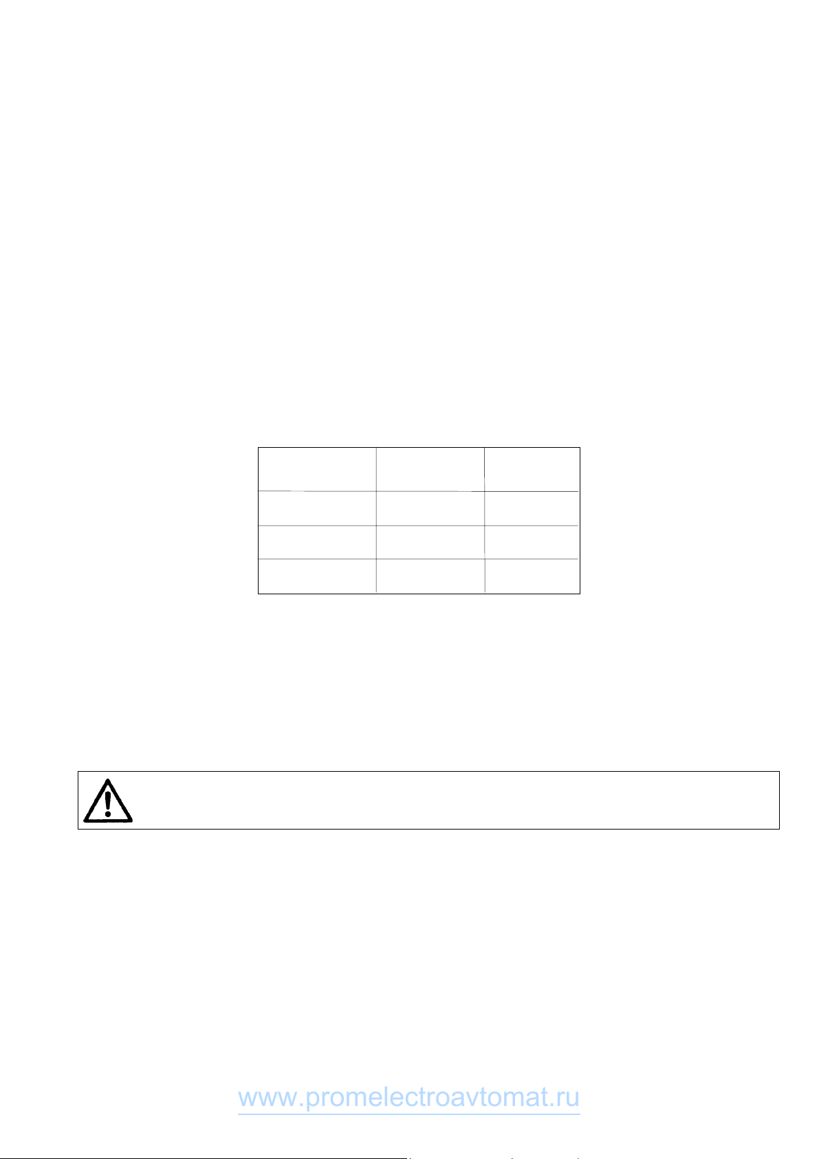
Machine noise level
The machine noise level has been measured in accordance with the standards ISO3746, ISO 11204 at the top sewing speed.
Laeq = equivalent noise level of the machine proper on its working place, converted to the % of machine operating time (dB) -
see the Table.
2. Machine description
It is a single-needle post bed sewing machine with two-step upper feed and lower wheel feed, with needle feed during the first
feeding step. The principal mechanisms are seated in antifriction bearings, rocking shafts and pins, in plain bearings. The feed is
transmitted from the stitch length regulation mechanism via friction clutch to the lower feed shaft, and from it by a roller chain
to the feed wheel. The top roller is driven from the lower feed shaft via indented belt, upper feed shaft, through the gear
transmission, vertical articulated shaft, and bevel gearing. The needle feed is derived from the same mechanism as the top roller/
feed wheel feed.The stitch length can be adjusted by a dial situated on the machine arm.
Caution!
Sewing speed prescribed as top limit speed for a given operation must not be exceeded under the risk of damage to
the feeding mechanism.
The reverse stitching is controlled by a hand lever or by a microswitch. A sewing set with interchangeable throat plate inlays
corresponding to the chosen needle size and distance between the needle axis and the work trimmer is mounted on the machine.
Top rollers with ø25 or ø 35 mm are available.The vertical hook is fitted with positive bobbin case opening and is secured by
overload release clutch with adjustable release moment. The machine uses a wick lubrication system with central oil supply.
The machine is fitted with standard vertical hook situated to the left of the needle, with friction-type bobbin winder. The machine
can be fitted with thread trimmer, electromagnetically actuated top roller lifting and reverse stitching, accessory lighting with
halogen lamp and, as the case may be, with further equipment. In machines without electromagnetically actuated top roller
lifting, the lifting is actuated by a knee lever or, for deliveries to Czech customers, by left-side treadle. In higher sub-classes, the
stop motor is either situated on the machine table top or as a minimotor integrated on the machine head.
The machine stand is fitted with a wedge and, depending on the top roller lifting version, with one or two treadles. The lower
horizontal work trimmer, spring-biassed both upwards, serves to trim he lining edge in inner and outer arches as well as in acute
angles. The trimmer knife is driven by a lever system from a separate motor situated under the bed plate. When switched out by
a press-button, it automatically takes up its inoperative position, and automatically switches on again when returned by the lower
lever to its operative position. The trimming motion length is adjustable. Various trimmer knives and a tilting sewn work guide can
be ordered with the machine.
Machine Noise level % of machine
type in dB operating time
4181i-3XX-100 82 20
4181i-3XX-200 79 20
4181i-3XX-300 73 20
www.promelectroavtomat.ru
2
3. Machine sub-classes and sewing categories
3.1 Sub-class
Table 1
* only for Czech republic
3.2 Sewing categories
This code indication includes the equipment assembled on the machine head, both necessary equipment and optional equip-
ment. The standard configuration of the equipment has been preset, according to the under mentioned table, in the factory which
includes only necessary equipment. If the buyer demands a different configuration then the factory allocates a new code
indication.
Table 2
Standard configuration - the numbers in brackets stand for ordering Nos. when ordering separately the Equipment in question
(needles - delivered in 10 pcs pack).
4. Survey of equipment
This survey does not include the equipment assembled on the stand.
4.1 Basic necessary equipment (at least one of each from the following group of equipment is assembled)
4.1.1 Needles
M 159 - needle 134 LL size 80
M 160 - needle 134 LL size 100
M 161 - needle 134 LL size 130
4.1.2 Wheel feeders
M 060 - wheel feeder with pitch of teeth 0.4 mm
M 059 - wheel feeder with pitch of teeth 0.6 mm
M 058 - wheel feeder with pitch of teeth 1.2 mm
4.1.3 Top rollers holders
M 156 - holder for the top roller ø 25 mm
M 157 - holder for the top roller ø 35 mm
M 295 - holder for the top roller ø 45 mm
4.1.4 Top rollers
M 172 - top roller ø 25 mm
M 173 - top roller ø 35 mm
M 174 - rubberized top roller ø 25 mm
M 175 - rubberized top roller ø35 mm
M 310 - smooth top roller ø 25 mm
M 311 - smooth top roller ø 35 mm
M 296 - top roller ø 45 mm - width 3.8 mm
M 297 - top roller ø 45 mm - width 2.0 mm
Type of the Hook Top roller lift Reverse stitching Thread
machine trimmer
Class-sub-clas Standard Via knee Treadle Via electro Via electro Via hand Via electro
-sewing small lever mag. + mag. + lever mag. +
category knee lever treadle hand lever
4181i-311-XXX
4181i-321-XXX*
4181i-347-XXX
4181i-357-XXX*
••••
•
••
••
•
Type Needle size Top roller Wheel feeder Throat plate insert Throat plate
Width of hole/distance
between the needle axis
Class-sub-class Diameter Pitch of teeth and the work trimmer line
-sewing category 0.01mm mm mm mm -
80 35 0,4 1,2/0,8
4181i-3XX-100 (S548 000220) (M 173) (M 060) (M 096)
100 35 0,4 1,5/1,2
4181i-3XX-200 (M 093)
(S548 000250) (M 173) (M 060) (M 097)
4181i-3XX-300 130 35 0,6 2/1,5
(S548 000245) (M 173) (M 059) (M 150)
•
•
•
•
www.promelectroavtomat.ru
3
4.1.5 Throat plate
M 091 - throat plate
4.1.6 Throat plate inserts
M 096 - insert for throat plate (for needle 60-80; trimmed edge 0.8)
M 097 - insert for throat plate (for needle 80-110; trimmed edge 1.2)
M 150 - insert for throat plate (for needle 110-140; trimmed edge 1.5)
M 199 - insert for throat plate (for needle 60-80; trimmed edge 0.8; stitch length max. 2 mm)
M 200 - insert for throat plate (for needle 80-110; trimmed edge 1.2; stitch length max. 2 mm)
4.1.7 Trimmer knife
M 170 - trimmer knife 119 202
4.1.8 Guide
M 018 - sewn work guide
4.1.9 Connecting cables of the head to the drive
M 163 - connecting cable to the drive EFKA DC 1600/DA82GA; EFKA VD 552/6F82FA and EFKA VD 554/6F82FA
M 055 - connecting cable without any specified drive (with free cable end)
Note: For the machine provided with a minimotor, the cable is component part of the drive thereof.
4.2 Optional equipment
M 010 - built-in lighting (including transformer 230/12V)
M 242 - setting gauge
4181 311001V - high mortality spare parts kit in plastic box for sub-class without thread trimmer
4181 347001V - high mortality spare parts kit in plastic box for sub-class with thread trimmer
S794 222012 - halogen lighting (12 V, 20 W - contains transformer)
5. Technical data
Table 3
Stitch type Double thread lock-stitch 301
Stitch length max. 5 mm ±10%
Top roller stroke 5.5 ±0.5 mm - via hand lever
12.5 ±1 mm via knee lever, treadle, electromagnet
Hook R 816 - vertical small
Needle System 134 LL; LR; EK; D
Trimmer knife 119 202 (in table No. 4 indicated *)
Driving unit Stopmotor min. 0.4 kW
Weight of the head max. 52 kg
Weitght of the stand max. 60 kg
Height of post bed 173 mm
Opening space of machine head 270 x 298 mm
Dimension of bed plate 178 x 518 mm
Sewing Sewn material Distance be- Stitch length Labelled Number Sewing Hook
category tween the number of of needle speed
needle axis polyester
and the work thread
trimmer line
Standard
mm - mm mm mm - - 0,01mm 0,01mm SPM SPM
-100
-light 0,8 2 0,8 2 3 70 80-60 80 60-80 2500 3500 R 816
-200
-medium 1 2 1,2 2,5 5 40 50-30 100 80-110 2500 3000 R 816
-300 -me-
dium heavy 1,5 2 1,5 3 5 20 30-20 130 110-140 2000 2000 R 816
Thickness of one
layer
Number of layers
Standard
Standard
Maximum
Standard
Range
Standard
Range
Standard
Maximum
www.promelectroavtomat.ru
4
Sewn material fine leather, boxcalf, goat leather, box patent leather, split
leather, lining, leathers, artificial leather, etc.,
medium-weight leathers, textile materials, also in combi-
nation with artrificial leathers
Trimmed material lining of relatively stiff materials - max. 2.5 mm
Distance between the needle axis and the work trimmer line 0.8 - 1.5 mm (according to sewing category)
Power outut of the work trimmer motor 25 W
Stroke frequency of the work trimmer knife 3300 strokes/min (constant)
Stroke range of the work trimmer knife 1.4 to 4.2 mm (adjustable)
Length of trimmed thread ends 8 - 11 mm
Input machine with stop motor 600 W
Equivalent level of acoustic pressure of the sole machine
at work place by 20% use of the machine during
a shift under standard sewing conditions 82 dB/A
Layout dimensions of the machine (including the stand) 1060 x 550 mm
Height of the machine (including the stand) 1680 mm
Applicable knives
Tab. 4
The upper No. in the column - Ordering No. - applies to orders placed with the company Maier, the lower one for those placed with
Minerva.
* supplied as standard can be ordered with Minerva as well to be ordered with the company Maier
Grinding the work trimmer knife
To obtain due quality of trimming, the knife should be ground on special grinding machines at short intervals (of about 2 to 5
hours) corresponding to the durability of the knife trimmer edge. The special grinding machines are produced by the following
companies:
FORTUNA WIEN GmBH, A-1151 WIEN-Pelzgasse 13, Postfach 91
MAIER UNITAS GmBH, NÜRTINGER Strasse 19, D-7316, KÖNGEN, Postfach 1130
Tooling steel, For normal lining
long cutting edge, material with
front end turned up cross-sections
High-speed steel, For very soft and
long cutting edge, synthetic materials
front end turned up with cross-sections
Tooling steel, For normal lining
long cutting edge material without
smooth top cross-sections
High-speed steel, For very soft and
long cutting edge, synthetic materials
smooth top without cross-sections
Tooling steel, For normal lining
short cutting edge, material with
front end turned up cross-sections and
tihgt curves
Tooling steel, For normal lining
short cutting edge, material without
smooth top cross-sections,
with tight curves
119 202 *
S425 311018
10,5 2,5
119 202 HSS
S425 311019
119 444
S425 311021
10,5 2,5
119 444 HSS
119 714 - 05
S425 311023
8,5 2,5
119 715 - 05
S425 311024
Ordering No. Side of Height of Illustrations Features Applications
trimmer (mm) trimmer (mm)
www.promelectroavtomat.ru
5
6. Operation of the machine
6.1 Threading a thread
Caution! Risk of injury!
Before threading a thread, turn the main switch
off and wait until the machine stops!
Thread the threads as it is shown in picture.
Caution!
Not following the correct method of threading a
thread may cause serious damage to the function
of the machine.
6.2 Bobbin thread winding
- Insert the bobbin (1).
- Spool counter-clockwise manually onto the bobbin, mini-
mum six threads of the lower thread (3).
- Insert the thread ends into the equipment (4) and cut off the
ends.
- Press the lever (2) until it reaches its limit.
- Switch on the machine.
- The winder will automatically switch off after winding.
- Take off the hook bobbin and cut off the end in the equip-
ment (4).
- The nut (5) is instrumental to thread tension control for
winding. Turning clockwise sense the thread tension is in-
creased and the single threads are more firmly fixed on the
bobbin.
- The tension cannot be so extensive as far as slipping of the
winder friction drive has occured.
6.3 Inserting the bobbin and threading
the lower thread
Caution! Risk of injury!
Turn the main switch off and wait until the motor
stops!
- Tilt the shutter (1) up.
- Insert the bobbin (2) with thread end (3) in the direction as
shown in the picture.
- Pass the thread through the notch (4) and then through the
gap between the part (5) and the hook (6) into the notch (7),
as shown in illustration.
- Close the hook cover (8) and cut with scissors the thread
end close at the cover.
3
2
7
5
4
1
8
6
1
2
4
3
5
www.promelectroavtomat.ru
6
6.4 Regulating the thread tension
The thread tension must conform to the thickness of the sewn
threads, thickness and hardness of sewn material (thin and
soft material will fold with high tension) and the kind of seam.
An ordinary fitting seam should be formed with stitches knit-
ted in the middle of the sewn material.
A decorative seam is mostly used with rough threads (20) on
thin material and it has tied up threads on the reverse side of
the material for achieving a decorative appearance.
Thread tension adjustment is by standard sewing (par. 5, ta-
ble 3) conditions in accordance with table No. 4.
If achieving of a decorative seam with stitch knitting on the
underside is wished, it is necessary to decrease the upper
thread tension, it is carried out by turning of nuts (1), in the
counter-clockwise sense.
Thread tension
Table 4
Sewing Kind of seam Identified Maximum
category value upper tension of
thread tension lower thread
NN
1- 31
2 - 4.5 1.5
3Fitting 8 2
Decorative 5
If the maximum lower thread tension exceeds the
values given in table No. 4, it may cause problems
in the beginning of sewing after the previous
thread trim.
Measurement of tension is done by dynamometer.
Warning:
The upper thread tensioner has been loosened automatically
after every trimming and top roller lifting. In these cases the
thread tension cannot be measured.
Regulating the thread tension
Caution! Risk of injury!
Before regulating the lower thread tension, turn
the main switch off and wait until the motor stops.
The upper thread tension is adjusted with nuts (1). Its clock-
wise turning increases the tension.
The tension of the auxiliary tensioner (3) should be as low as
possible but it should be on a level so that the upper thread
would not pull out of the tensioner when the work is being
removed.
The lower thread tension is adjusted with a screw (2). Its clock-
wise turning increases the tension.
Tension correlation rate defines the depth of the seam tied
through. The result of raising the upper tension will be the
decreasing depth of tie through. The opposite will apply with
the lower thread.
1
2
Montání ev
Okrasný ev
1
3
Provázání stehu
Provázání stehu
www.promelectroavtomat.ru
7
6.5 Needle replacement
Caution! Risk of injury!
Before remowing and inserting the needle turn
the main switch off and wait until the motor
stops!
- Turn with the hand wheel as far as the top needle (1) position
has been reached.
- Loosen the screw (2) and take the needle out.
- When inserting a new needle, care is to be taken that groove
(3) above the needles eye was in the same direction as the
hook.
- Tighten the screw (2).
The inserted needle must respond to the sewing
category according to paragraph No. 5, table 3.
Otherwise it will cause damage to sewing, or even-
tually the machine could be broken.
6.6 Regulation of pressing the top roller
The pressing of the top roller should be as low as possible but
on a level so that the top roller would not fly over when needle
comes off the material and that the feeding power got over
the thread pull by stitch tightening.
By turning of the screw (1) clockwise pressing of the top roller
has been increased, by counter-clockwise turning pressing of
the top roller has been decreased.
6.7 Lifting the top roller up
Mechanical lifting of the top roller is enabled by means of the
hand lever (1), which contemporarily, after it has been lifted in
the arrow direction, is locking the top roller in its top position
and turning (adjustment) of the machine is possible. The top
roller can be lifted via knee lever or left treadle - depending on
the machine sub-class. Automatical lifting by means of elec-
tromagnet is described in the paragraph No. 7.
When lifting top roller via knee lever or the treadle
or electromagnet, the needle must be in the upper
position and the machine has to come to a full
stop.
1
1
1
3
2
www.promelectroavtomat.ru
8
6.8 Reverse stitching
The change of direction of sewn work can be mechanically
controlled via a reverse stitching lever (1) by its depression in
the arrow direction (down). The sub-class defines whether
the machine has electromagnetic reverse stitching  see para-
graph No. 7.
6.9 Stitch length adjustment
Stitch length adjustment is by dial (2) by its turning. Turning
clockwise stitch length is decreased, turning counter-clock-
wise stitch is length increased.
6.10 Safety clutch
The machine is provided with a safety clutch which disen-
gages the driving unit, when the hook is blocked. Reconnec-
tion must be done in the following way:
Caution! Risk of injury!
Before assembly turn the main switch off and wait
until the motor stops!
- Turn the manually operated wheel as far as you can reach the
suitable point for inserting a screwdriver into the space(1).
- Continue turning the manually operated wheel in direction
of the arrow located on it, until you feel the drop in of the
safety clutch.
6.11 To exchange and set the trimmer knife
Caution! Risk of injury!
Before assembly turn the main switch off and wait
until the motor stops!
- Loosen the screw (1).
- Take the trimmer knife (2) out in the direction of the arrow.
- Set the angle of 180° on the handwheel (lower dead point of
the needle). Tilt the machine head and rotate by hand the
drive shaft of the work trimmer so as to set the knife holder
to its rear end position.
- Insert the new trimmer knife (2) and set it at the distance
A= 0.5 to 1 mm from the needle.
- Loosen the screw (1).
- Be sure in maintaining the minimum clearance between the
knife trimmer edge and the throat plate insert, correct even-
tually the distance with the screw (4) after having loosened
the screw (3). Tighten the screw (3).
1
1
2
A
3
4
1
2
www.promelectroavtomat.ru
9
7. Electronic control of the machine
(it is valid for sub-classes equipped with stop motor)
7.1 Control of sewing by means of control elements
7.1.1 Via treadle (treadle positions and function
possibilities)
The position of the treadle is read by the reader, which can
recognise 16 levels. Its meaning is shown on the table.
Treadle Treadle Meaning
position
-2 Foot full backwards Command for thread
trimming (seam finishing)
-1 Foot slightly Commandlifting
the top roller up
0 Neutral position Note
1Slightly forwards Command releasing
top roller
2Continually Sewing at minimum
forwards speed (1. gear)
3Continually Sewing at second
forwards speed level
: : :
13 Fully forwards Sewing at maximum
speed (12. gear)
Note: It is possible to pre-adjust the needle position (up/down)
and foot position (up/down) by stopping in seam (introduc-
ing the treadle in neutral position). Foot position (up/down)
after seam finishing (pressing the treadle by foot fully back-
wards).
7.1.2 Via pushbutton panel
There are four built-in pushbuttons in the panel with fixed
adjustable functions:
T1 - bar operation (by pressing this pushbutton during sew-
ing the sewn work is feed back)
T2 - needle up/down (each press of the pushbutton changes
the needle position)
T3 - temporary cancelling (recalling) bar (in case) the bar is
pre programmed at the start and end of the seam, by
pressing the pushbutton down will uniformly switch off;
if it is not chosen it will switch on by pressing the push-
button
T4 - revolutions limitation (valid for motor Efka DA82GA)
- reduction of pressure of the presser foot for Mini-stop
EFKA DA320 (see The instructions for assembling with
Mini-stop, par. 5.2.4)
7.1.3 Via control panel Efka V 810/V 820
These functions are standardly assigned to the pushbuttons
A, B:
A - cancelling (recalling) the bar (the same function as T3 of
the pushbutton panel)
B - needle up/down(the same function as T2 of the push-
button panel)
Note: function of the A,B pushbuttons can be changed by
different adjustment of parameters 293,294 (see the parame-
ters list of driving unit Efka DA82GA).
T 1 T 2 T 3 T 4
1 ÷ 13
0
-1
-2
www.promelectroavtomat.ru
10
7.2 Adjustment of automatic functions via control
panel for stop motor
7.2.1 By using stop motor Efka with panel V 810
Functioning pushbuttons engagement:
Pushbutton P Recalling and program mode termination
Pushbutton E Confirmation of program mode changes
Pushbutton + Increase of value displayed in program
mode
Pushbutton - Decreasing value displayed in program
mode
Pushbutton 1 Start bar SINGLE/DOUBLE/OFF
Pushbutton 2 End bar SINGLE/DOUBLE/OFF
Pushbutton 3 Automatic top roller lifting after stopping
at the seam ON/OFF
Automatic top roller lifting after thread
trimming (end of seam) ON/OFF
Automatic presser foot lifting after
thread trimming (end of seam) ON/OFF
Automatic reduction of pressure of the
presser foot ON/OFF (only for DC 1550/
DA320; see The instructions for assem-
bling with Mini-stop, par. 5.2.4)
Pushbutton 4 Basic position of needle UP/DOWN
Pushbutton A For cancelling respectively recalling
the bar
Pushbutton B For switch over the needle position
UP/DOWN respective shift pushbutton
in program mode
Symbol C Connection of automatic revolutions
Symbol D Connection of lighting barrier
Symbol E The machine is running
Symbol F The revolutions limitation switch on
Symbol G Connection of lower thread controller,
flashing light indicator symbol when
the threads supply on the bobbin is
running out
The arrows on the display indicate switching the functions
which are displayed by symbols above the pushbuttons on.
7.2.1.1 Adjustment by means of buttons with fixed setting
function
Note: It is important to finish the seam in order to reach
effective button pressing (press the treadle fully backwards
down).
Setting start bar:
Drive enables sewing start bar automatically. It is necessary to
choose the type (single, double, off) and number of stitches
which will be sewn forwards and backwards.
The arrow above its symbol shows the type of bar (chosen by
gradually pressing pushbutton 1). It will be displayed follow-
ing after pressing pushbutton 1.
Arv (SAv) XXX - number of stitches of start (fancy) bar for-
wards or
Arr (SAr) XXX - number of stitches of start (fancy) bar back-
wards) for about 3 sec.
At this time you can change the number of stitches by gra-
dually pressing the pushbutton + or -.
By setting the treadle to its zero position during the sewing of
the start bar (par. 215 - OFF), you stop the machine at the
completion of the start bar. You can then switch on the sewn
work cutter.
Setting end bar:
The same applies to the start bar (setting by the means of
pushbutton 2).
Erv (SEv) XXX - end (fancy) bar number of stitches forwards
Err (SEr) XXX - end (fancy) bar number of stitches backwards
Note: The last section of end bar must have at least 3 stitches.
www.promelectroavtomat.ru
11
Foot position adjustment by stopping at the seam (by neutral
position of treadle) and after finishing seam (by neutral posi-
tion of treadle):
Setting is by means of pushbutton 3, arrow indication above
the corresponding symbol.
Needle position adjustment by stopping at the seam:
Setting is by means of pushbutton 4.
7.2.1.2 Setting by means of parameters
Drive memory contains the parameters which enables sewing
system tuning. These parameters have exact meaning and
they are divided into 3 levels. Further parameters which are
available only for operation will be quoted. Each parameter
has its (sequence) number and value.
General procedure by changing parameters of operation level:
- switch the main switch on or finish the seam by pressing the
treadle fully backwards down
- press pushbutton P on the panel V 810
- it will be displayed on the display F 000 (000 it is the number
of parameter)
- by several times pressing + (or -) set the requested number
of parameter
- push pushbutton E down and it will be shown the value of
parameter on the display
- you can change the value by means of pushbutton + or 
- by pushing pushbutton E down you will change the sequence
to the following number of parameter
- by pushing pushbutton P down you will leave the mode of
changing parameters
Note: 1. For permanent memory storing of changed pa-
rameter, it is necessary to press treadle forwards
down after changing of parameters.
2. Mode of changing parameters is possible only af-
ter finishing of the seam.
Number of stitches in bars:
Number of stitches is stored in parameters number.
No. of parameter Value range Description
of parameter of parameters
000(080) 0-254 Number of stitches of
start (fancy) bar forwards
001(081) 0-254 Number of stitches of
start (fancy)bar backwards
002(082) 0-254 Number of stitches of
end (fancy) bar backwards
003(083) 0-254 Number of stitches of
end (fancy)bar forwards
Sewing according to sewing program:
Drive with panel V810 automatically enables sewing of 1 seam
with setting number of stitches. It is necessary to set in corre-
sponding number of stitches, and initialisation of sewing pro-
gram.
No. of parameter Value range Description
of parameter of parameters
007 0-254 Number of stitches
015 ON/OFF ON/OFF sewing under
sewing program
www.promelectroavtomat.ru
12
ON/OFF thread trimmer:
No. of parameter Value range Description
of parameter of parameters
013 ON/OFF Thread trimmer
ON/OFF
7.2.2 By using stopmotor Efka with panel V 820
Functioning pushbuttons engagement:
Pushbutton P Call and termination of programming mode
Pushbutton E Confirmation when changing programming
mode
Pushbutton + Increasing the value displayed in program-
mingmode
Pushbutton - Reducing the value displayed in program-
ming mode
Pushbutton 1 Start bar SINGLE/DOUBLE/OFF
Pushbutton 2 Stitch counting FORWARD/BACK/OFF
Pushbutton 3 Light barrier function
LIGHT-DARK/DARK-LIGHT/OFF
Pushbutton 4 End bar
SINGLE/DOUBLE/OFF
Pushbutton 5 Function
TRIMMING/TRIMMING+EJECTOR/OFF
Pushbutton 6 Automatic top roller lifting after having
stopped inside the seam ON/OFF
Automatic top roller lifting after trimming
ON/OFF
Automatic presser foot lifting after thread
trimming (end of seam) ON/OFF
Automatic reduction of pressure of the
presser foot ON/OFF (only for DC 1550/
DA320; see The instructions for assem-
bling with Mini-stop, par. 5.2.4)
Pushbutton 7 Basic needle position UP/DOWN
Pushbutton 8 Lower thread waste controlling ON/OFF
Pushbutton 9 Operation pushbutton - programmable
Pushbutton 0 Programming/processing of 40 possible
sewing sections (seams)
Pushbutton A For cancelling or calling the bar
Pushbutton B For switching needle position UP/DOWN,
resp. shifting pushbutton in the program-
ming mode
Symbol C Designating symbol C for code number
Symbol D Designating symbol F for parameter
number
Symbol E Programme number in TEACH IN mode
Symbol F Seam number in TEACH IN mode
Symbol G Run blocking ON
Symbol H Blocked insertion by pushbutton
Symbol I Fault reporting
Symbol J Insertion of stitch number in TEACH IN
mode
Symbol K Connected lower thread controller, flash-
ing symbol when running out thread re-
serve on bobbin
Symbol L Limitation of revolutions ON
Symbol M Right needle disconnected
symbol N Evening stitches for light barriee in the
TEACH IN mode
AB
CD E F GHI JKLMNOPQ
www.promelectroavtomat.ru
13
Symbol O Machine is running
Symbol P Automatic revolutions ON
Symbol Q Left needle disconnected
The arrows on the display indicate switching the functions
which are displayed by symbols above the pushbuttons on.
7.2.2.1 Adjustment by means of buttons with fixed setting
function
Note: It is important to finish the seam in order to reach
effective button pressing (press the treadle fully backwards
down).
Setting start bar:
Drive enables sewing start bar automatically. It is necessary to
choose the type (single, double, off) and number of stitches
which will be sewn forwards and backwards.
The arrow above its symbol shows the type of bar (chosen by
gradually pressing pushbutton 1). It will be displayed follow-
ing after pressing pushbutton 1.
Arv (SAv) XXX - number of stitches of start (fancy) bar for-
wards or
Arr (SAr) XXX - number of stitches of start (fancy) bar back-
wards for about 3 sec.
At this time you can change the number of stitches by gra-
dually pressing the pushbutton + or -.
By setting the treadle to its zero position during the sewing of
the start bar (par. 215 - OFF), you stop the machine at the
completion of the start bar. You can then switch on the sewn
work cutter.
Setting end bar:
The same applies to the start bar (setting by the means of
pushbutton 4).
Erv (SEv) XXX - end (fancy) bar number of stitches forwards
Err (SEr) XXX - end (fancy) bar number of stitches backwards
Note: The last section of end bar must have at least 3 stitches.
Foot position adjustment by stopping at the seam (by neutral
position of treadle) and after finishing seam (by neutral posi-
tion of treadle):
Setting is by means of pushbutton 6, arrow indication above
the corresponding symbol.
Needle position adjustment by stopping at the seam:
Setting is by means of pushbutton 7.
Trimming switched ON/OFF:
To be set using pushbutton 5.
Sewing programme ON:
To be switched on using pushbutton 0.
Switching ON/OFF the function of the pushbutton F:
The pushbutton F on panel can have assigned one of the
following functions: Sst - softstart
SrS - fancy bar
Frd - reverse angle after trimming
7.2.2.2 Setting by means of parameters
Drive memory contains the parameters which enables sewing
system tuning. These parameters have exact meaning and
they are divided into 3 levels. Further parameters which are
available only for operation will be quoted. Each parameter
has its (sequence) number and value.
General procedure by changing parameters of operation level:
- switch the main switch on or finish the seam by pressing the
treadle fully backwards down
- press pushbutton P on the panel V 820
- on the display there is no data shown
- by depressing the pushbutton E several times, set the
required parameter (without having displayed the parameter
number)
AB
CD E F GHI JKLMNOPQ
www.promelectroavtomat.ru

Other manuals for 4181i

1

Other Duerkopp Adler Sewing Machine manuals

Duerkopp Adler 1180-5 Troubleshooting guide

Duerkopp Adler

Duerkopp Adler 1180-5 Troubleshooting guide

Duerkopp Adler 589 User manual

Duerkopp Adler

Duerkopp Adler 589 User manual

Duerkopp Adler 550-16-23 User manual

Duerkopp Adler

Duerkopp Adler 550-16-23 User manual

Duerkopp Adler 251-140040 User manual

Duerkopp Adler

Duerkopp Adler 251-140040 User manual

Duerkopp Adler 4181i-1 Guide

Duerkopp Adler

Duerkopp Adler 4181i-1 Guide

Duerkopp Adler 745-7 Guide

Duerkopp Adler

Duerkopp Adler 745-7 Guide

Duerkopp Adler Tape Feeder User manual

Duerkopp Adler

Duerkopp Adler Tape Feeder User manual

Duerkopp Adler 1230i-6 Guide

Duerkopp Adler

Duerkopp Adler 1230i-6 Guide

Duerkopp Adler 171 User manual

Duerkopp Adler

Duerkopp Adler 171 User manual

Duerkopp Adler 869-M PREMIUM User manual

Duerkopp Adler

Duerkopp Adler 869-M PREMIUM User manual

Duerkopp Adler 171 Guide

Duerkopp Adler

Duerkopp Adler 171 Guide

Duerkopp Adler 467-65 Guide

Duerkopp Adler

Duerkopp Adler 467-65 Guide

Duerkopp Adler 867-70 ECO User manual

Duerkopp Adler

Duerkopp Adler 867-70 ECO User manual

Duerkopp Adler 510 User manual

Duerkopp Adler

Duerkopp Adler 510 User manual

Duerkopp Adler 887 User manual

Duerkopp Adler

Duerkopp Adler 887 User manual

Duerkopp Adler 550-767 User manual

Duerkopp Adler

Duerkopp Adler 550-767 User manual

Duerkopp Adler 511 User manual

Duerkopp Adler

Duerkopp Adler 511 User manual

Duerkopp Adler 550-12 Guide

Duerkopp Adler

Duerkopp Adler 550-12 Guide

Duerkopp Adler 578 Guide

Duerkopp Adler

Duerkopp Adler 578 Guide

Duerkopp Adler 69 User manual

Duerkopp Adler

Duerkopp Adler 69 User manual

Duerkopp Adler 211 Guide

Duerkopp Adler

Duerkopp Adler 211 Guide

Duerkopp Adler 550-19-2 Guide

Duerkopp Adler

Duerkopp Adler 550-19-2 Guide

Duerkopp Adler 530-211 User manual

Duerkopp Adler

Duerkopp Adler 530-211 User manual

Duerkopp Adler 527 User manual

Duerkopp Adler

Duerkopp Adler 527 User manual

Popular Sewing Machine manuals by other brands

Bernina 710 manual

Bernina

Bernina 710 manual

Janome COVER PRO 900CP instruction manual

Janome

Janome COVER PRO 900CP instruction manual

Brother BAS-612 parts book

Brother

Brother BAS-612 parts book

Viking 2780 operating manual

Viking

Viking 2780 operating manual

Singer MX231 instruction manual

Singer

Singer MX231 instruction manual

Singer 6105 user manual

Singer

Singer 6105 user manual

Brother BAS-364E parts list

Brother

Brother BAS-364E parts list

Singer 271K11 Service manual

Singer

Singer 271K11 Service manual

Singer 144W103 parts list

Singer

Singer 144W103 parts list

DURKOPP ADLER 381 operating instructions

DURKOPP ADLER

DURKOPP ADLER 381 operating instructions

Dürkopp Adler 1767 operating instructions

Dürkopp Adler

Dürkopp Adler 1767 operating instructions

DURKOPP ADLER 275 Series Spare parts

DURKOPP ADLER

DURKOPP ADLER 275 Series Spare parts

Bernina 1230 Service manual

Bernina

Bernina 1230 Service manual

Beisler 1500/70 Series operating instructions

Beisler

Beisler 1500/70 Series operating instructions

DURKOPP ADLER D868 Service instructions

DURKOPP ADLER

DURKOPP ADLER D868 Service instructions

Happy Industrial Corporation HCS2 Instruction book

Happy Industrial Corporation

Happy Industrial Corporation HCS2 Instruction book

Singer DSXII List of parts

Singer

Singer DSXII List of parts

Brother Entrepreneur Pro PR-1000 Operation manual

Brother

Brother Entrepreneur Pro PR-1000 Operation manual

manuals.online logo
manuals.online logoBrands
  • About & Mission
  • Contact us
  • Privacy Policy
  • Terms and Conditions

Copyright 2025 Manuals.Online. All Rights Reserved.