manuals.online logo
Brands
  1. Home
  2. •
  3. Brands
  4. •
  5. Dukane
  6. •
  7. Power Supply
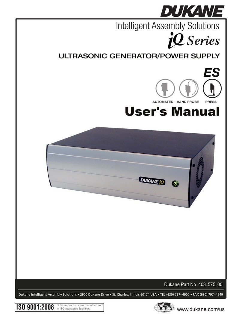
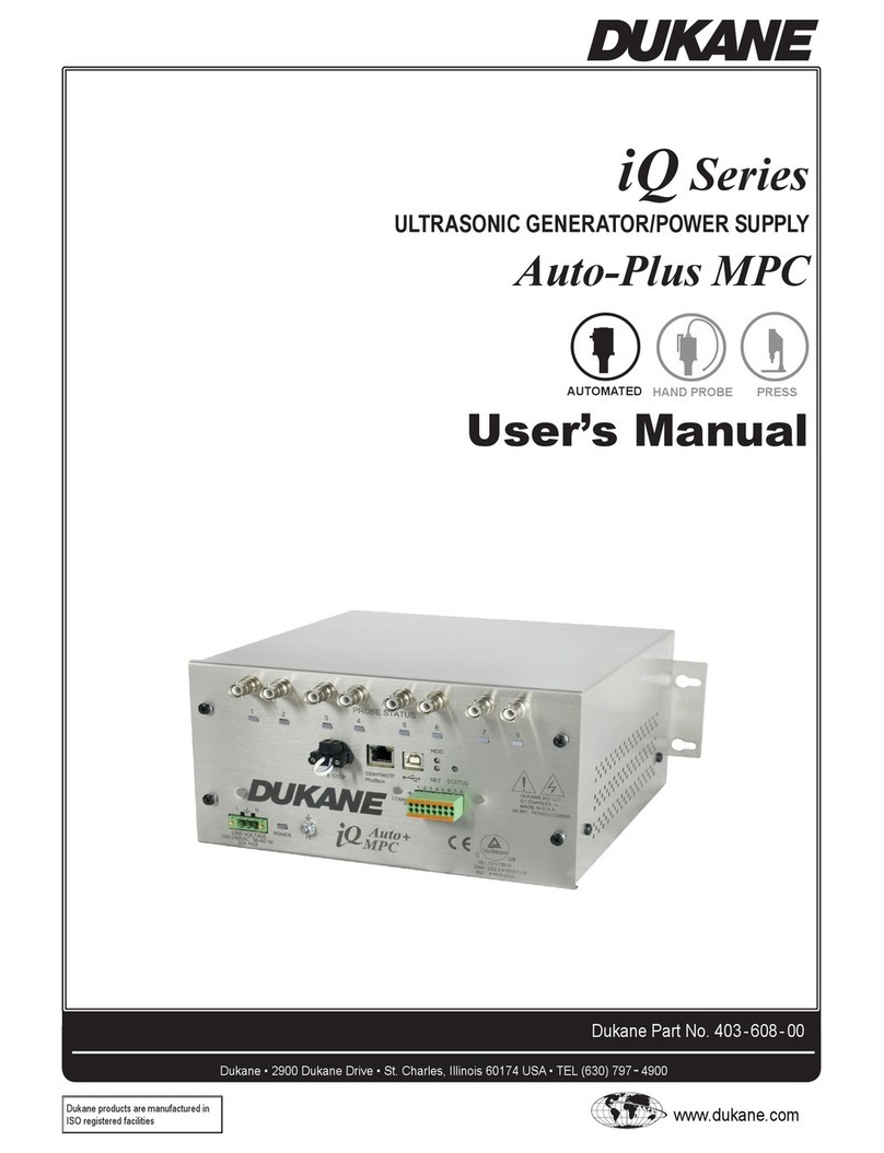
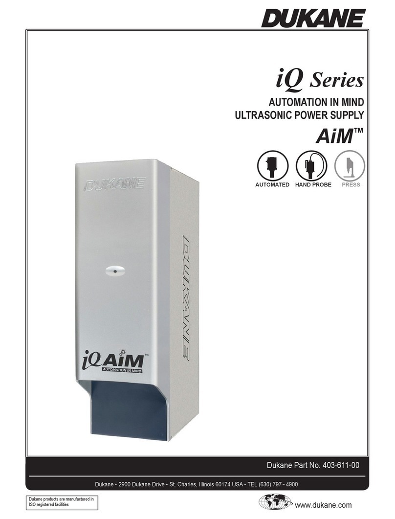
  8. •
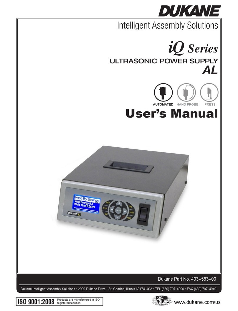
  9. Dukane iQ Series Installation and operating instructions

Dukane iQ Series Installation and operating instructions

AN502 (REV 07) © Dukane 2016. All Rights Reserved.
Page 1 of 16
DUKANE
APPLICATION NOTE
AN502
Intelligent Assembly Solutions
iQ Series
ULTRASONIC PROBE SYSTEM
LS/LS-E
Automation Interface Guidelines
AN502 (REV 07) © Dukane 2016. All Rights Reserved.
Page 2 of 16
DUKANE
APPLICATION NOTE
AN502
Intelligent Assembly Solutions
Index
System Inputs
System Input Cable Pinouts / System Input Cables 3
Connecting System Inputs (PLC Sourcing Output Card) 4
Connecting a PLC Sinking Output Card 5
Connecting a Relay Contact Closure 6
System Outputs
System Output Cable Pinouts / System Output Cables 7
Connecting System Outputs (PLC Sourcing Input Card) 8
Connecting a PLC Sinking Input Card 9
Connecting a Relay Contact Closure 10
Remote Setup Switching 11
Connecting an Automation Safety Circuit 12
iQ LS / LS-E Automation Controlled Probe Generator Timing Diagrams
LS / LS-E (Weld-by-Automation) Timing Diagram 13
LS / LS-E (Weld-by-Time) Timing Diagram 14
LS / LS-E with MPC (Weld-by-Automation) Timing Diagram 15
LS / LS-E with MPC (Weld-by-Time) Timing Diagram 16
AN502 (REV 07) © Dukane 2016. All Rights Reserved.
Page 3 of 16
DUKANE
APPLICATION NOTE
AN502
Intelligent Assembly Solutions
System Input Cable Pinouts
Pin
Color
Description
J2-1
BLK
+22V CURRENT LIMITED POWER SUPPLY (250mA MAX)
J2-2
WHT
+22V RETURN (iQ CHASSIS GROUND)
J2-3
RED
REMOTE SETUP SELECTION BIT 0 INPUT
J2-4
GRN
REMOTE SETUP SELECTION BIT 1 INPUT
J2-5
ORN
REMOTE SETUP SELECTION BIT 2 INPUT
J2-6
BLU
REMOTE SETUP SELECTION BIT 3 INPUT
J2-7
WHT/BLK
REMOTE SETUP SELECTION BIT 4 INPUT (NOT USED)
J2-8
RED/BLK
ULTRASOUND ACTIVATION / CYCLE START INPUT
J2-9
GRN/BLK
AUTOMATION THRUSTER CONTROL INPUT (NOT USED)
J2-10
ORN/BLK
FRONT PANEL CONTROL LOCK
J2-11
BLU/BLK
PRESS INHIBIT FOR HAND PROBES (DUKANE USE ONLY)
J2-12
BLK/WHT
SYSTEM LATCH RESET INPUT
J2-13
RED/WHT
ISOLATED COMMON (SOURCING OR SINKING INPUTS)
J2-14
GRN/WHT
OPEN CONNECTION
J2-15
BLU/WHT
AUTOMATION CYCLE STOP INPUT
Note: For detailed signal descriptions, please refer to the product manual.
System Input Cables
Part Number
Length
200-1380-03M
3 meters
200-1380-05M
5 meters
200-1380-07M
7 meters
200-1380-09M
9 meters
200-1380-11M
11 meters
200-1380-13M
13 meters
AN502 (REV 07) © Dukane 2016. All Rights Reserved.
Page 4 of 16
DUKANE
APPLICATION NOTE
AN502
Intelligent Assembly Solutions
Connecting System Inputs
All System Inputs are optically isolated from the internal circuits and can be connected to sinking or sourcing PLC output
cards. The inputs will draw approximately 10mA with a 24Vdc supply. The Systems Inputs can also be configured for a
contact closure if necessary.
PLC Sourcing Output Card
Notes:
1. All System Inputs share the same Isolated Common (J2-13). It is critical that the isolated common is connected
to the positive supply or ground.
2. J2-1 can be used in place of the 24Vdc supply. If so, J2-13 must be connected to J2-2.
Warning: Any connection to the Ultrasound Activation/Cycle Start Input (J2-8) or the Automation Thruster Control Input
(J2-9) should be disabled during an emergency stop condition.
+24Vdc Supply
(+30Vdc max)
PLC Output Card
Contact closure or
transistor output
iQ System Inputs
0Vdc Return
Isolated Common
J2-13
PLC Digital Outputs
Sourcing Current
iQ Digital Input
Sinking Current
AN502 (REV 07) © Dukane 2016. All Rights Reserved.
Page 5 of 16
DUKANE
APPLICATION NOTE
AN502
Intelligent Assembly Solutions
Connecting a PLC Sinking Output Card
Notes:
1. All System Inputs share the same Isolated Common (J2-13). It is critical that the isolated common is connected
to the positive supply or ground.
2. J2-1 can be used in place of the 24Vdc supply. If so, J2-13 must be connected to J2-1 and 0Vdc to J2-2.
Warning: Any connection to the Ultrasound Activation/Cycle Start Input (J2-8) or the Automation Thruster Control Input
(J2-9) should be disabled during an emergency stop condition.
+24Vdc Supply
(+30Vdc max)
PLC Output Card
Contact closure or
transistor output
iQ System Inputs
0Vdc Return
Isolated Common
J2-13
PLC Digital Outputs
Sinking Current
iQ Digital Input
Sourcing Current
AN502 (REV 07) © Dukane 2016. All Rights Reserved.
Page 6 of 16
DUKANE
APPLICATION NOTE
AN502
Intelligent Assembly Solutions
Connecting a Relay Contact Closure
Notes:
1. All System Inputs share the same Isolated Common (J2-13). It is critical that the isolated common is connected
to the positive supply or ground.
2. Dukane’s current limited power supply can be substituted for the +24Vdc supply above. Connecting +22Vdc
(J2-1) to Isolated Common (J2-13) would allow a dry contact closure between any System Input and 0V Return
(J2-2). Connecting the System Inputs in this way would be similar to activating DPC series System Inputs.
Warning: Any connection to the Ultrasound Activation/Cycle Start Input (J2-8) or the Automation Thruster Control Input
(J2-9) should be disabled during an emergency stop condition.
iQ Digital Input
Sourcing Current
+24Vdc Supply
(+30Vdc max)
PLC Output Card or External Relay
iQ System Inputs
0Vdc Return
Isolated Common
J2-13
PLC Digital Outputs
Sinking Current
AN502 (REV 07) © Dukane 2016. All Rights Reserved.
Page 7 of 16
DUKANE
APPLICATION NOTE
AN502
Intelligent Assembly Solutions
System Output Cable Pinouts
Pin
Color
Description
J3-1
BLK
+22V CURRENT LIMITED POWER SUPPLY (250mA MAX)
J3-2
WHT
OPEN CONNECTION
J3-3
RED
+22V RETURN (iQ CHASSIS GROUND)
J3-4
GRN
PROGRAMMABLE STATUS OUTPUT 1
J3-5
ORN
PROGRAMMABLE STATUS OUTPUT 2
J3-6
BLU
ULTRASOUND ACTIVE STATUS OUTPUT
J3-7
WHT/BLK
ANY FAULT STATUS OUTPUT
J3-8
RED/BLK
PRESS TRIGGER STATUS OUTPUT
J3-9
GRN/BLK
SYSTEM OVERLOAD STATUS OUTPUT
J3-10
ORN/BLK
SYSTEM ONLINE STATUS OUTPUT
J3-11
BLU/BLK
PRESS TOP OF STROKE STATUS OUTPUT
J3-12
BLK/WHT
CURRENT LOOP STATUS OUTPUT (NOT USED)
J3-13
RED/WHT
ANALOG MONITOR OUTPUTS GROUND (iQ CHASSIS GROUND)
J3-14
GRN/WHT
NOT USED (iQ CHASSIS GROUND)
J3-15
BLU/WHT
POWER SIGNAL MONITOR OUTPUT (1mV = 1 WATT)
J3-16
BLK/RED
AMPLITUDE MONITOR OUTPUT (10.0V = 100%)
J3-17
WHT/RED
AMPLITUDE/POWER REGULATION STATUS OUTPUT
J3-18
ORN/RED
MPC SYSTEM READY STATUS OUTPUT (NOT USED)
J3-19
BLU/RED
SYSTEM POWER STATUS OUTPUT
J3-20
RED/GRN
BAD PART STATUS OUTPUT
J3-21
ORN/GRN
GOOD PART STATUS OUTPUT
J3-22
BLK/WHT/RED
SYSTEM READY STATUS OUTPUT
J3-23
WHT/BLK/RED
SUSPECT PART STATUS OUTPUT
J3-24
RED/BLK/WHT
ISOLATED COMMON (SINKING AND SOURCING OUTPUTS)
J3-25
GRN/BLK/WHT
OPEN CONNECTION
Note: For detailed signal descriptions, please refer to the product manual.
System Output Cables
Part Number
Length
200-1381-03M
3 meters
200-1381-05M
5 meters
200-1381-07M
7 meters
200-1381-09M
9 meters
200-1381-11M
11 meters
200-1381-13M
13 meters
AN502 (REV 07) © Dukane 2016. All Rights Reserved.
Page 8 of 16
DUKANE
APPLICATION NOTE
AN502
Intelligent Assembly Solutions
Connecting System Outputs
All System Outputs are optically isolated from the internal circuits and can be connected to sinking or sourcing PLC input
cards. When J3-1 is used to power the outputs, the total maximum output current for all outputs combined is 250mA. If
an external supply is used, as shown in the drawing below, each output can sink or source up to 500mA.
PLC Sourcing Input Card
Notes:
1. All System Outputs share the same Isolated Common (J3-24). It is critical that the isolated common is connected
to the positive supply or ground.
2. J3-1 can be used in place of the 24Vdc supply. If so, J3-24 must be connected to J3-3.
iQ Digital Outputs
Sinking Current
+24Vdc Supply
iQ System Outputs
PLC Input Card
0Vdc Return
Isolated Common J3-24
PLC Digital Input
Sourcing Current
AN502 (REV 07) © Dukane 2016. All Rights Reserved.
Page 9 of 16
DUKANE
APPLICATION NOTE
AN502
Intelligent Assembly Solutions
Connecting a PLC Sinking Input Card
Notes:
1. All System Outputs share the same Isolated Common (J3-24). It is critical that the isolated common is connected
to the positive supply or ground.
2. J3-1 can be used in place of the 24Vdc supply. If so, J3-24 must be connected to J3-1 and 0Vdc to J3-3.
iQ Digital Outputs
Sourcing Current
iQ System Outputs
PLC Input Card
0Vdc Return
Isolated Common J3-24
PLC Digital Input
Sinking Current
+24Vdc Supply
(+30Vdc max)
AN502 (REV 07) © Dukane 2016. All Rights Reserved.
Page 10 of 16
DUKANE
APPLICATION NOTE
AN502
Intelligent Assembly Solutions
Connecting a Relay Contact Closure
Notes:
1. All System Outputs share the same Isolated Common (J3-24). It is critical that the isolated common is connected
to the positive supply or ground.
2. J3-1 can be used in place of the 24Vdc supply. If so, J3-24 must be connected to J3-3.
+24Vdc Supply
iQ Digital Outputs
Sinking Current
iQ System Outputs
RELAY
0Vdc Return
Isolated Common J3-24
AN502 (REV 07) © Dukane 2016. All Rights Reserved.
Page 11 of 16
DUKANE
APPLICATION NOTE
AN502
Intelligent Assembly Solutions
Remote Setup Switching
J2-7
J2-6
J2-5
J2-4
J2-3
Setup
J2-7
J2-6
J2-5
J2-4
J2-3
Setup
Selected
Selected
0
0
0
0
0
1
N/A
N/A
N/A
N/A
N/A
17
0
0
0
0
1
2
N/A
N/A
N/A
N/A
N/A
18
0
0
0
1
0
3
N/A
N/A
N/A
N/A
N/A
19
0
0
0
1
1
4
N/A
N/A
N/A
N/A
N/A
20
0
0
1
0
0
5
N/A
N/A
N/A
N/A
N/A
21
0
0
1
0
1
6
N/A
N/A
N/A
N/A
N/A
22
0
0
1
1
0
7
N/A
N/A
N/A
N/A
N/A
23
0
0
1
1
1
8
N/A
N/A
N/A
N/A
N/A
24
0
1
0
0
0
9
N/A
N/A
N/A
N/A
N/A
25
0
1
0
0
1
10
N/A
N/A
N/A
N/A
N/A
26
0
1
0
1
0
11
N/A
N/A
N/A
N/A
N/A
27
0
1
0
1
1
12
N/A
N/A
N/A
N/A
N/A
28
0
1
1
0
0
13
N/A
N/A
N/A
N/A
N/A
29
0
1
1
0
1
14
N/A
N/A
N/A
N/A
N/A
30
0
1
1
1
0
15
N/A
N/A
N/A
N/A
N/A
31
N/A
1
1
1
1
16
N/A
N/A
N/A
N/A
N/A
32
Note: Remote setup mode is available in the LS-E model. It is enabled by selecting “Automation” from the front panel Setup
screen. These system inputs receive a Binary code from the automation that is used to select a setup to be used for the next
welding cycle. Setup selections 17-32 are reserved and are not available (N/A). An external +24VDC supply can be used
instead of the generator internal supply. See the drawings on pages 4 and 5 for more information.
Remote Setup Inputs
Remote Setup Selection Bit 1 Input
J2-5
J2-4
Remote Setup Selection Bit 2 Input
J2-6 Remote Setup Selection Bit 3 Input
PLC
Sourcing
Outputs
Remote Setup Selection Bit 0 Input
J2-3
+22VDC Return (Ground)
Isolated Common
J2-2
J2-13
Remote Setup Inputs
Remote Setup Selection Bit 1 Input
J2-5
J2-4
Remote Setup Selection Bit 2 Input
J2-6 Remote Setup Selection Bit 3 Input
PLC
Sinking
Outputs
Remote Setup Selection Bit 0 Input
J2-3
+22VDC Power Supply
Isolated Common
J2-1
J2-13
AN502 (REV 07) © Dukane 2016. All Rights Reserved.
Page 12 of 16
DUKANE
APPLICATION NOTE
AN502
Intelligent Assembly Solutions
Connecting an Automation Safety Circuit
Notes:
1. To operate the LS / LS-E Generator, J17 (Left Side) and J17 (Right Side) must be maintained in a closed
connection.
2. If the connection between J17 (Left Side) and J17 (Right Side) is opened, the ultrasonic output will be disabled.
WARNING: Consult the appropriate local regulatory agency (OSHA, UL, CE, etc.) regarding all of the
safety requirements for your automated machine. Dukane is not responsible for injuries related to
improper safety circuits or safety guarding used in an automated machine. EN 12100-1/-2 and
EN 60204-1 safety standards are recommended.
Automation E-Stop (Abort) Switch
or Similar Safety Circuit
iQ E-Stop (Abort) Circuits
N.C.
Internal +22Vdc Supply
J17 (Left Side)
J17 (Right Side)
To System E-Stop (Abort) Relay
AN502 (REV 07) © Dukane 2016. All Rights Reserved.
Page 13 of 16
DUKANE
APPLICATION NOTE
AN502
Intelligent Assembly Solutions
iQ LS / LS-E Automation Controlled Probe Generator Timing Diagrams
L
LS
S
/
/
L
LS
S-
-E
E
(
(W
We
el
ld
d-
-b
by
y-
-A
Au
ut
to
om
ma
at
ti
io
on
n)
)
T
Ti
im
mi
in
ng
g
D
Di
ia
ag
gr
ra
am
m
Normal Weld Cycle -A normal weld cycle lasts as long as the U/S Activate input is in a high state. This cycle shows the
timing between activation/deactivation of the U/S Activate input, U/S Status output and Ready Status output signals.
The Ready Status Output: The Ready Status output is used to determine if the generator is ready to start a new weld
cycle. As seen in Figure 1, the Ready Status output requires a minimum of 3ms to change to its deactivated state after the
U/S Activate input is activated. For correct operation, a PLC controlling an LS or LS-E Automation generator must delay at
least 3ms after activating the U/S Activate input before checking the Ready Status output. At the end of a normal cycle,
the Ready Status output requires a minimum of 19.5ms to change to its activated state after the U/S Activate input has
deactivated. For correct operation, a PLC controlling an LS or LS-E Automation generator must delay at least 19.5ms
after deactivating the U/S Activate input before checking the Ready Status output. It is possible that the stack ring down
time (stack stops vibrating), which is stack and application dependent, will make this time much longer.
The U/S Status Output: The U/S Status output is used to determine when the generator has activated its ultrasound
ouput to the ultrasonic stack. As seen in Figure 1, the U/S Status output requires a minimum of 5ms to change to its
activated state. For correct operation, a PLC controlling an LS or LS-E Automation generator must delay at least 5ms after
activating the U/S Activate input before checking the U/S Status output. At the end of a normal cycle, the U/S Status
output requires a minimum of 18.0ms to change to its deactivated state after the U/S Activate input has deactivated. For
correct operation, a PLC controlling a LS or LS-E Automation generator must delay at least 18.0ms after deactivating the
U/S Activate input before checking the U/S Status output.
Weld Cycle with an Overload -This weld cycle shows the same timing relationship as a normal weld cycle except the
ultrasound output, indicated by the U/S Status output, is terminated early due to an overload condition.
The Any Fault Status Output: The Any Fault Status output is used to determine when the generator has terminated the
weld cycle due to an overload. When an overload occurs, the Any Fault Status output activates at the same time the U/S
Status output deactivates. The Ready Status output doesn’t activate until the U/S Activate output deactivates. The Ready
Status output requires a minimum of 20.0ms to change to its activated state after the U/S Activate input has deactivated.
For correct operation, a PLC controlling an LS or LS-E Automation generator must delay at least 20.0ms after deactivating
the U/S Activate input before checking the Ready Status output.The Any Fault Status output will deactivate the next time
the U/S Activate input is activated, but is delayed up to 3ms.
The Overload Status Output: The Overload Status output is also used to determine when the generator has terminated
the weld cycle due to an overload.The Overload Status output has the same timing as the Any Fault Status output and will
deactivate the next time the U/S Activate input is activated, but is delayed up to 3ms.
Figure 1: LS / LS-E Weld-by-Automation Cycle Timing Diagram
AN502 (REV 07) © Dukane 2016. All Rights Reserved.
Page 14 of 16
DUKANE
APPLICATION NOTE
AN502
Intelligent Assembly Solutions
L
LS
S
/
/
L
LS
S-
-E
E
(
(W
We
el
ld
d-
-b
by
y-
-T
Ti
im
me
e)
)
T
Ti
im
mi
in
ng
g
D
Di
ia
ag
gr
ra
am
m
N
No
or
rm
ma
al
l
W
We
el
ld
d
C
Cy
yc
cl
le
e:
:
This is a Weld-by-Time cycle, meaning the Ultrasound output lasts as long as the Time Setting,
which is 200ms in this case. A LS / LS-E generator requires communications interface such as Ethernet/IP to configure
the weld by Time, Peak Power, and Energy settings. While it is strongly reccomended that the communications network
be used instead of the descrete I/O, the network and descete I/O can be used together. Figure 2 shows the timing for
weld cycles that were configured via the network interface, but ultrasound is activated using the US Activate input instead
of the network. As with Weld-by Automation, the Ready Status output should be used to determine if the generator is
ready to start a new weld cycle. As seen in Figure 2, the Ready Status output requires a minimum of 3ms to change to its
deactivated state after the U/S Activate input is activated. At the end of the normal weld time, there is stack ring down
time, which is stack and application dependent, and may make this time much longer. The Ready Status output activates
after a minimum of 1.5ms or when the ring down time is complete, whichever occurs first. For correct operation, a PLC
controlling an LS / LS-E generator must delay at least 1.5ms after activating the U/S Activate input before checking the
Ready Status output. Since the U/S Status output takes up to 5.0ms to change state, a 5.0ms minimum delay is required
when monitoring this output. If a network is connected to the generator, then the US Activation can be controlled by the
network. The same is true for monitoring the status outputs. The delays will vary with the network based on network
settings, number of devices on the network, etc.
Cycle With an Overload: This weld cycle shows the same timing relationship except the ultrasound output, indicated by
U/S Status, is terminated early, in this case after 100ms, due to an overload condition.. The Any Fault Status and
Overload Status outputs activate at the same time U/S Status deactivates. The Ready Status output activates after a
minimum of 3.0ms or when the ring down time is complete, whichever occurs first. The Any Fault Status and Overload
Status outputs will deactivate the next time the U/S Activate input is activated, but are delayed up to 3.0ms.
Figure 2: LS / LS-E Weld-by-Time Cycle Timing Diagram
AN502 (REV 07) © Dukane 2016. All Rights Reserved.
Page 15 of 16
DUKANE
APPLICATION NOTE
AN502
Intelligent Assembly Solutions
L
LS
S
/
/
L
LS
S-
-E
E
W
Wi
it
th
h
M
MP
PC
CQ
Q
(
(W
We
el
ld
d-
-b
by
y-
-A
Au
ut
to
om
ma
at
ti
io
on
n)
)
T
Ti
im
mi
in
ng
g
D
Di
ia
ag
gr
ra
am
m
Probe selection changed between weld cycles: Although the probe selection can be changed at any time this method
is the safest and most predictable. The PLC program should monitor the MPC Ready output and when it becomes active
change the probe selection using the Remote Setup inputs. This will insure that the stack ring down from the previous
cycle is finished. After a delay of at least 33ms, the MPC Ready output will change to inactive (low in this case) again and
stay that way for 33ms. See Figure 3 where Remote Setup 0 changes from low to high. The PLC should continue to
monitor the MPC Ready output and start the next cycle when MPC Ready activates (high in this case).
Probe selection changed during a weld cycle: Alternately the Remote Setup inputs can change during the weld cycle.
The MPC circuitry will not select a new probe when the MPC Ready output is not active. As can be seen in Figure 3,
Remote Setup 0 input is changed to inactive before the weld cycle completes. Once the stack ring down completes the
relays switch so that probe 1 is selected almost immediately, but the relay takes up to 8ms to settle. The MPC Ready
output will remain inactive for 33ms after ring down completes. In this case the PLC must monitor the MPC Ready output
and not activate the U/S Activate input until the MPC Ready signal is active.
Figure 3 LS / LS-E with MPCQ Weld Cycle (Weld-by-Automation)
Timing Diagram Notes: All Signals are active high and the grey areas indicate that the output could be either high or low.
The symbol indicates a time break so that the time where nothing is happening doesn’t need to be shown.
AN502 (REV 07) © Dukane 2016. All Rights Reserved.
Page 16 of 16
DUKANE
APPLICATION NOTE
AN502
Intelligent Assembly Solutions
Dukane
Intelligent Assembly Solutions
2900 Dukane Drive
St. Charles, IL 60174 USA
Tel: (630) 797-4900
Fax: (630) 797-4949
http://www.dukane.com/
Disclaimer: Dukane Corporation assumes no responsibility for any errors which may appear in this document, reserves the right to change devices or
specifications detailed herein at any time without notice, and does not make any commitment to update the information contained herein.

Other manuals for iQ Series

8

This manual suits for next models

2

Other Dukane Power Supply manuals

Dukane ES User manual

Dukane

Dukane ES User manual

Dukane AiM iQ Series User manual

Dukane

Dukane AiM iQ Series User manual

Dukane AiM iQ Series User manual

Dukane

Dukane AiM iQ Series User manual

Dukane iQ Series AL User manual

Dukane

Dukane iQ Series AL User manual

Dukane iQ Auto-Plus 20AT060-U Series User manual

Dukane

Dukane iQ Auto-Plus 20AT060-U Series User manual

Dukane iQ Series User manual

Dukane

Dukane iQ Series User manual

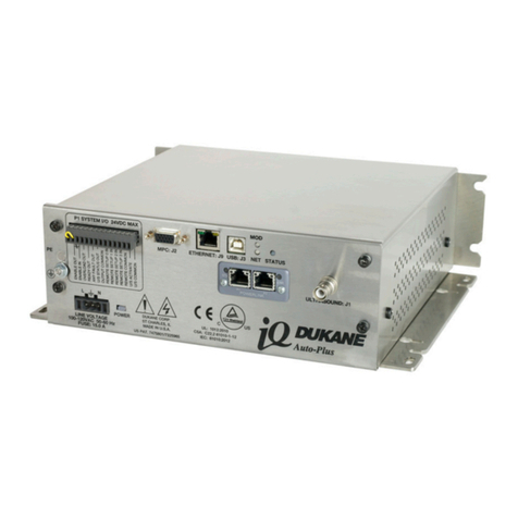
Dukane Auto-Plus MPC iQ Series User manual
Dukane

Dukane Auto-Plus MPC iQ Series User manual

Dukane iQ Series LS User manual

Dukane

Dukane iQ Series LS User manual

Dukane iQ Series User manual

Dukane

Dukane iQ Series User manual
Popular Power Supply manuals by other brands

Licht-Technik PS75-04 manual

Licht-Technik

Licht-Technik PS75-04 manual

JVA M1.5 Installation and user manual

JVA

JVA M1.5 Installation and user manual

CEA EA500-518WH-1 Series manual

CEA

CEA EA500-518WH-1 Series manual

Puls ML30.102 installation manual

Puls

Puls ML30.102 installation manual

PACOM PAC-24WM0808 user manual

PACOM

PACOM PAC-24WM0808 user manual

Dialight SafeSite DHZCPSD4C8 manual

Dialight

Dialight SafeSite DHZCPSD4C8 manual

AGRO ELECTRO DL 3200 user manual

AGRO ELECTRO

AGRO ELECTRO DL 3200 user manual

Huawei UPS5000-H-800K-NTN quick guide

Huawei

Huawei UPS5000-H-800K-NTN quick guide

XS Power Batteries Performance IntelliSUPPLY PSC15 user guide

XS Power Batteries

XS Power Batteries Performance IntelliSUPPLY PSC15 user guide

Antec VP550P V2 user manual

Antec

Antec VP550P V2 user manual

Scientific PSD3203 user manual

Scientific

Scientific PSD3203 user manual

Best Power Patriot SMT 280 A user manual

Best Power

Best Power Patriot SMT 280 A user manual

Riden RD6012P instructions

Riden

Riden RD6012P instructions

Altronix LPS3AC Installation instructions manual

Altronix

Altronix LPS3AC Installation instructions manual

axing ZU 99-22 Operation instructions

axing

axing ZU 99-22 Operation instructions

Pulsar PSBEN 1012B manual

Pulsar

Pulsar PSBEN 1012B manual

Altronix VertiLine8 Series installation guide

Altronix

Altronix VertiLine8 Series installation guide

Honeywell HP300ULM Product installation document

Honeywell

Honeywell HP300ULM Product installation document

manuals.online logo
manuals.online logoBrands
  • About & Mission
  • Contact us
  • Privacy Policy
  • Terms and Conditions

Copyright 2025 Manuals.Online. All Rights Reserved.