dunkermotoren ServoTube 25 / 38 User manual

User guide
Dunkermotoren GmbH | Allmendstraße 11 | D-79848 Bonndorf/ Schwarzwald
Version 03/2018
Operating Manual ServoTube 25/38 Module
Publication Ref: UM03016/B
Betriebanaleitung ServoTube 25/38 Module
Publikation Ref: UM03016/B
ServoTube 25 / 38 Module

Version 03.2018 | Page/ Seite 2 www.dunkermotoren.com
WARRANTY
Dunkermotoren guarantees its equipment against faulty components for a period of twelve months from delivery.
Replacement components will be free of charge. Dunkermotoren shall not in any event be liable for consequential
damage or loss.
Dunkermotoren operates a customer care facility and all requests for repair and replacement should be directed to
the Customer Care Department. The serial number of the equipment should be quoted in any communications. The
right to change specication and price is reserved by Dunkermotoren.
DISCLAIMER
Dunkermotoren makes no guarantees of any kind with regard to this User Guide. Dunkermotoren shall not be liable
for errors contained herein or for consequential or incidental damages incurred as a result of acting on information
contained in the manual.
CUSTOMER CARE
For enquiries relating to the operation and use of the ServoTube 25/38 Module described in this User Guide, please
contact the Sales department, Telephone : +49 (0)7703 930-0.

Version 03.2018 | Page/ Seite 3 www.dunkermotoren.com
ServoTube 25/38 Module
USER GUIDE
Contents
Preliminary pages
Title page ..................................................................................................................... 1
Copyright notice / disclaimer........................................................................................ 2
Contents list (this page) ............................................................................................... 3
Warnings ..................................................................................................................... 4
Cautions....................................................................................................................... 4
Reader’s notes............................................................................................................. 5
Chapters
1 Product overview ................................................................................................... 6
2 Installation.............................................................................................................. 7
3 Maintenance ........................................................................................................ 12
4 Service................................................................................................................. 23
Appendices
A Glossary of terms & Abbreviations....................................................................... 24
B Trouble Shooting.................................................................................................. 26
C Technical Specication ........................................................................................ 27

Version 03.2018 | Page/ Seite 4 www.dunkermotoren.com
WARNINGS
Warning symbols and meanings
In this User Manual warning symbols are used. These are intended to alert you to the potential hazards to personnel
which are associated with the equipment described, in all aspects of use, including handling, installation, operation
and maintenance.
Heart pacemakers. Personnel tted with pacemakers must not handle or work on this equipment.
Strong magnets. The thrust rod contains powerful magnets and will strongly attract ferrous objects.
Damage can occur to computer disks and credit cards.
Electric shock. Potentially lethal voltages may be present during the commissioning and servicing of
this equipment. Isolate and disconnect all sources of electrical supply before working on the equipment.
Particular care needs to be taken when working on or around motor phase connections.
Crush hazard. The forcer may move unexpectedly. Always isolate all sources of electrical supply before
working on the equipment.
Heavy object. May need two people to lift.
General hazard. Follow the advice given.
Electrical safety
This equipment must be earthed.
EMC precautions
This equipment is intended for use in a light industrial environment. It is recommended that the following precautions
be observed during installation:
• Keep all cable lengths to a minimum.
• Provide as much physical separation as possible between power and sensor cables. In particular, avoid long,
parallel runs of cables.
• Maintain screen continuity throughout the cable run.
• Use 360 degree screen terminations where possible. “Pig-tail” terminations are not recommended.
• Ensure compliance with any local electrical and EMC regulations in force at the time of installation. This is the
responsibility of the User.

Version 03.2018 | Page/ Seite 5 www.dunkermotoren.com
READER’S NOTES
GENERAL
This manual describes the Installation, Maintenance and Spares of the ServoTube module.
ASSOCIATED PUBLICATIONS
The following publications are associated with the ServoTube 25/38 Module User Guide.
Title Reference Number
ServoTube 25/38 Module Data sheet DS01100
Copley Xenus (XTL-S) User Guide -
Copley Xenus (XTL-S) Data Sheet -

Version 03.2018 | Page/ Seite 6 www.dunkermotoren.com
The ServoTube Module with fully integrated bearing
rail and position encoder oers unprecedented value in
high performance applications. The ServoTube Module
is a cost eective alternative to ballscrew and belt drive
systems where high speed and exibility are required.
accuracy, from a non-contact, integral position sensor.
The standard ServoTube position encoder output is
an industry standard 1V pk-pk sin/cos signal. For
applications requiring higher levels of accuracy, the
ServoTube Module is available with a fully integrated
optical position encoder giving a resolution of up to 1
micron.
The non-contact nature of the direct linear drive results
in life expectancy far above that for typical belt drive
and ballscrew systems, with the added advantage of no
deterioration in accuracy or repeatability over the entire
life of the product.
The ServoTube Module is an ideal OEM solution for
easy integration into pick-and-place gantry and general
purpose material handling machines. The load is
mounted directly to the forcer giving a very stable base.
Servotube Modules can be easily integrated with each
other or with other ServoTube products to create multi-
axis systems with minimal design eort.
The ServoTube has superior thermal eciency, radiating
heat uniformly. High duty cycles are possible without the
need for forced-air or water cooling.
Servotube is complemented by a range of matched, self
tuning servo-ampliers and indexers complete with plug
and play cabling. Ampliers interface easily to PLCs and
feature CANopen network connectivity for distributed
control applications.
Chapter 1
Product Overview
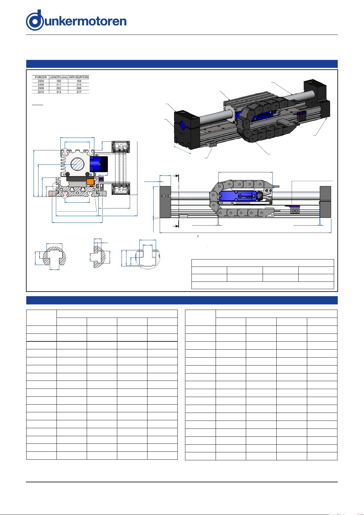
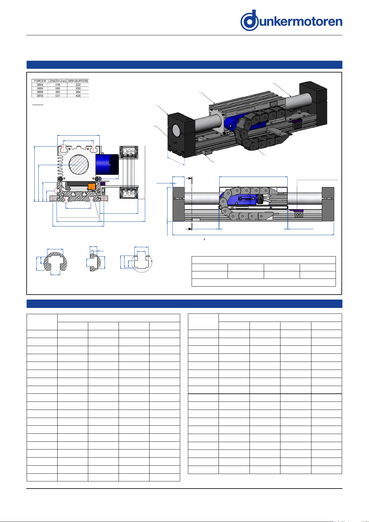
Eight models deliver a continuous force of 51 to 276 N
(11 to 62 lb) with peak forces of up to 1860 N (418 lb).
Standard stroke lengths of 21 mm to 1323 mm are
available.
The magnetic design of ServoTube generates
12 micron repeatability and 350 micron absolute

Version 03.2018 | Page/ Seite 7 www.dunkermotoren.com
Chapter 2
Installation
UNPACKING
• Check packaging for signs of damage.
• Remove packaging. Do not discard. In the event of items requiring return, it is recommended that the original
packaging be used.
• Metal surfaces may be hot or below 0oC following prolonged storage.
• Ensure that the delivery note correctly reects your order and the items delivered.
• Check equipment for signs of damage. Never use the equipment if it appears damaged in any way.
• Read the User Guide before installing and using this equipment.
INSTALLATION
Intended operating environment
This equipment is intended for use in an environment within the following conditions:
Operating temperature 0 to +40 °C
Storage temperature -20 °C to +70
°C
Altitude (above mean sea
level) 1000 m
Overvoltage category II
Pollution degree 2
EMC light industrial
Mechanical
Mounting module to user’s surface
For all modules, ensure that the mounting surface is as at as possible. The module can be mounted by two methods:
• Using the system clamp top xings. Both sides should be clamped with a distance between clamp centres of no
more than 150 mm. Each M6 bolt should be tightened to a torque of 15 Nm.
• Using the M5 T-nut slots on the underside of the module. This requires access from underneath the mounting
surface. Both sides should be xed with a distance between xing centres of no more than 150 mm. Each M5
bolt should be tightened to a torque of 12 Nm.
All torque gures are non lubricated i.e. no thread lock.
Mounting user’s payload to module moving forcer
The payload is mounted to the moving forcer top surface using the T-nut slots provided. It is recommended that a
minimum of four xings are used.
• On the SM25 modules, the xings are M5 and should be tightened to a torque of 12 Nm.
• On the XM38 modules, the xings are M6 and should be tightened to a torque of 20 Nm.

Version 03.2018 | Page/ Seite 8 www.dunkermotoren.com
Length
Stroke
2504 2506 2508 2510
253 23 - - -
278 48 - - -
304 74 23 - -
330 100 49 - -
355 125 74 23 -
381 151 100 49 -
406 176 125 74 23
432 202 151 100 49
458 228 177 126 75
483 253 202 151 100
509 279 228 177 126
535 305 254 203 152
560 330 279 228 177
586 356 305 254 203
612 382 331 280 229
637 407 356 305 254
663 433 382 331 280
Length
Stroke
2504 2506 2508 2510
689 459 408 357 306
714 484 433 382 331
740 510 459 408 357
766 536 485 434 383
791 561 510 459 408
817 587 536 485 434
868 638 587 536 485
919 689 638 587 536
971 741 690 639 588
1022 792 741 690 639
1073 843 792 741 690
1125 895 844 793 742
1176 946 895 844 793
1227 997 946 895 844
1279 1049 998 947 896
1330 1100 1049 998 947
1381 1151 1100 1049 998
SM25 OUTLINE DRAWINGS
SM25 STROKE TABLES
85
DRAG CHAIN
FOR CABLE ROUTING
(LARGER SIZE OPTIONAL)
SYSTEM CLAMPS
(MOUNTED NOT MORE
THAN 150mm APART)
EACH SIDE, IF REQUIRED
BEARING
LUBRICATION PORT
LH THRUST ROD
SUPPORT
FORCER
MAGNETIC THRUST ROD
(NOT LOAD BEARING)
RH THRUST ROD
SUPPORT
(SEE NOTE)
33.0
93.00.5
NOM.
STANDARD SYSTEM LENGTH 253mm MIN. TO 1381mm MAX.
2.0
(RUBBER BUFFER)
2.0
(RUBBER BUFFER)
FORCER LENGTH
0.5
EACH END
A
A
CUSTOMER ADJUSTABLE LIMIT
SWITCHES (OPTIONAL)
FACTORY SET FOR 5.0mm FROM
END OF STROKE
NOTE: RH THRUST ROD SUPPORT SHOWN IS FOR 2504 MODULES ONLY, FOR ALL
OTHER SIZES THIS SUPPORT WILL BE AS LH THRUST ROD SUPPORT.
68
86
64
17
18.5
38.5
65
94
50
50
102
(CLAMP BOLT CENTRES)
78
21
C
B
D
SECTION A-A
1
SYSTEM LENGTH (
0.5) = STROKE REQUIRED + FORCER LENGTH + 66.0mm (THRUST ROD SUPPORTS)
+ 4.0mm (RUBBER BUFFERS) [+10.0mm FOR LIMIT SWITCHES]
LINEAR ENCODER (OPTIONAL)
DATUM ACTUATION AT
20.0mm FROM END OF STROKE
5.2
4.8
2.5
8.2
DETAIL C
6.2
10.5
4.5
9.0
DETAIL B
6.2
11.0
5.3
10.3
10.9
DETAIL D
23
CABLES:
Ø7.6 POWER CABLE
1.
Ø5.8 SENSOR CABLE
2.
Ø4.5 ENCODER CABLE (OPTIONAL)
3.
SLOTS FOR M5 T-NUTS &
M6 SQUARE / HEX. NUTS
SLOTS FOR M4 SQUARE NUTS
SLOTS FOR M6 T-NUTS &
M8 SQUARE / HEX. NUTS
(FOR LARGER DRAG CHAIN)
(ORDER REF. I3)
Approximate module mass (kg)
2504 2506 2508 2510
(0.0108 x L)+2.35 (0.0108 x L)+3.04 (0.0108 x L)+3.58 (0.0108 x L)+3.96
where L = Length in mm

Version 03.2018 | Page/ Seite 9 www.dunkermotoren.com
85
MAGNETIC THRUST ROD
(NOT LOAD BEARING)
BEARING
LUBRICATION PORT
SYSTEM CLAMPS
(MOUNTED NOT LESS
THAN 150mm APART)
EACH SIDE, IF REQUIRED
DRAG CHAIN
FOR CABLE ROUTING
(LARGER SIZE OPTIONAL)
FORCER
THRUST ROD
SUPPORT
FORCER LENGTH
38.0
109.00.5
NOM.
STANDARD SYSTEM LENGTH 338mm MIN. TO 1621mm MAX.
0.5
EACH END
2.0
(RUBBER BUFFER)
2.0
(RUBBER BUFFER)
A
A
CUSTOMER ADJUSTABLE LIMIT
SWITCHES (OPTIONAL)
FACTORY SET FOR 5.0mm FROM
END OF STROKE
(FOR LARGER DRAG CHAIN)
(ORDER REF. I3)
86
76
84.0
38.5
73
110
38
50
102
(CLAMP BOLT CENTRES)
60.0
90
21
B
C
D
SECTION A-A
1
SYSTEM LENGTH ( 0.5) = STROKE REQUIRED + FORCER LENGTH + 76.0mm (THRUST ROD SUPPORTS)
+ 4.0mm (RUBBER BUFFERS) [+10.0mm FOR LIMIT SWITCHES]
LINEAR ENCODER (OPTIONAL)
DATUM ACTUATION AT 20mm
FROM END OF STROKE
6.2
4.5
10.5
9.0
DETAIL B
SLOTS FOR M4 SQUARE NUTS
4.8
2.5
5.2
8.2
DETAIL C
8.2
14.0
6.8
11.8
13.0
DETAIL D
23
CABLES:
Ø7.6 POWER CABLE
1.
Ø5.8 SENSOR CABLE
2.
Ø4.5 ENCODER CABLE (OPTIONAL)
3.
SLOTS FOR M5 T-NUTS &
M6 SQUARE / HEX. NUTS
SLOTS FOR M6 T-NUTS &
M8 SQUARE / HEX. NUTS
Approximate module mass (kg)
3804 3806 3808 3810
(0.0108 x L)+4.26 (0.0108 x L)+5.23 (0.0108 x L)+6.21 (0.0108 x L)+7.19
where L = Length in mm
Length
Stroke
3804 3806 3808 3810
338 40 - - -
373 75 - - -
409 111 40 - -
445 147 76 - -
480 182 111 40 -
516 218 147 76 -
551 253 182 111 40
587 289 218 147 76
623 325 254 183 112
658 360 289 218 147
694 396 325 254 183
730 432 361 290 219
765 467 396 325 254
801 503 432 361 290
837 539 468 397 326
872 574 503 432 361
908 610 539 468 397
944 646 575 504 433
979 681 610 539 468
Length
Stroke
3804 3806 3808 3810
1015 717 646 575 504
1051 753 682 611 540
1086 788 717 646 575
1122 824 753 682 611
1158 860 789 718 647
1193 895 824 753 682
1229 931 860 789 718
1264 966 895 824 753
1300 1002 931 860 789
1336 1038 967 896 825
1371 1073 1002 931 860
1407 1109 1038 967 896
1443 1145 1074 1003 932
1478 1180 1109 1038 967
1514 1216 1145 1074 1003
1550 1252 1181 1110 1039
1585 1287 1216 1145 1074
1621 1323 1252 1181 1110
SM38 OUTLINE DRAWINGS
SM38 STROKE TABLES

Version 03.2018 | Page/ Seite 10 www.dunkermotoren.com
Electrical
All electrical connections to the ServoTube Module are made via two cables. One carries power to the forcer and the
other carries signals from the position sensor. These cables are supplied either pre-terminated for a specic drive
amplier or with ying leads. Where they are pre-terminated, simply plug the cables into the relevant connectors on
the drive amplier.
AMPLIFIER
Copley Xenus (XTL-S)
ESR new Amplier series
The connections for the three options are shown in the table below:
SENSOR FUNCTION D-(XTL-S) F-Flying leads N-ESR plug
+SIN 14 Blue 6
-SIN 13 Red 7
+COS 12 White 11
-COS 11 Brown 12
+5Vd.c. 4 Yellow 10
0V 5 Green 15
+TH (Thermistor) 10 Pink 5
-TH (Thermistor) 15 Grey 15
SCREEN 1+ shell Screen Shell
Connector type 15-way high
density D -15-way high
density D
Amplier connection J8 - X6.2
POWER FUNCTION
Forcer phase U 4 Black 1 U
Forcer phase V 3 Black 2 V
Forcer phase W 2 Black 3 W
Earth (forcer body) 1 Green/Yellow PE
SCREEN 1 Screen Shell
Connector type
4-way 5mm
pluggable
terminal
-4-way pluggable
terminal
Amplier connection J2 - X3

Version 03.2018 | Page/ Seite 11 www.dunkermotoren.com
ADDITIONAL ENCODER
If an additional encoder has been specied there will be a third cable that should be connected to the relevant
encoder input on the drive amplier used.
Connections are available via a 9-way D-sub male connector.
FUNCTION +5Vd.c. 0V A+ A- B+ B- Z+ Z- Screen
PIN NUMBER 5 1 2 6 4 8 3 7 Case
LIMIT SWITCHES
WARNING. These limit switches are not intended as safety devices or as part of a system
intended to ensure personal safety. When two switches are mounted in close proximity (as
in the case of a left and right limit switch), a minimum of 30mm spacing between sense areas
must be maintained.
If limit switches have been specied there will be an additional cable per limit switch. These should be connected to
the relevent I/O on the drive amplier.
The output for all types can be normally closed (NC) or normally open (NO) open collector transistor. The NC ouptuts
switch open when a limit is detected and current stops owing in the LOAD. The NO ouputs switch closed when a
limit is detected and current starts owing in the LOAD.
A red indicator shows when a limit is detected.
OVER-TEMPERATURE SENSOR
CAUTION. It is strongly recommended that the forcer over-temperature sensor is connected to
the drive amplier or servo controller at all times in order to reduce the risk of damage to the
forcer due to excessive temperatures.
Black (LOAD)
Blue (0V)
NPN
LOAD
Brown (+V)
Black (LOAD)
Blue (0V)
PNP
LOAD
Brown (+V)

Version 03.2018 | Page/ Seite 12 www.dunkermotoren.com
Chapter 3
Maintenance
WARNING
ISOLATE AND DISCONNECT ALL SOURCES OF ELECTRICAL SUPPLY BEFORE WORKING ON
THE EQUIPMENT.
PREVENTATIVE MAINTENANCE
ALL MODULES
Bearing System
The ServoTube modules are supplied as complete, ready to use mechanical systems. Each system incorporates a
prole rail re-circulating ball bearing system for support and guidance. The bearing carriages, to which the moving
forcer is attached, are fully charged with grease before delivery. During the life of the system, this grease will need to
be replenished. The interval for replenishment will vary depending on the parameters of operation. Systems carrying
heavy payloads and travelling at high speeds with fast acceleration and deceleration will need re-greasing more often
than systems carrying light payloads and travelling at slower speeds. However, as a general guide, re-greasing is
recommended at intervals of 1000 km.
In order to re-grease the bearing carriages eectively and with minimum spillage, a delivery tube with a specially
designed nozzle to engage with the lubrication nipples on the bearing carriages is required. These are available from
your supplier complete with a fully charged, small (70 g) side lever grease gun.
CAUTION. Dierent types of grease should never be mixed as they can cause damage
to the bearing rail due to their incompatibility. The bearing system must only be
lubricated via the bearing carriages. Do not lubricate the bearing rail. Do not lubricate
the thrust rod, it is not a bearing surface.

Version 03.2018 | Page/ Seite 13 www.dunkermotoren.com
RE-GREASING
Introduction
The ServoTube Modules are supplied as complete, ready to use, mechanical systems. Each system incorporates
a prole rail re-circulating ball bearing system for support and guidance. The bearing carriages, to which the forcer
is attached, are fully charged with grease before delivery. During the life of the system, this grease will need to be
replenished.
There is a standard bearing type supplied on ServoTube modules: HR type, general recommended re-greasing
interval of every 100Km of travel.
This interval will vary depending on the parameters of operation. Systems carrying heavy loads and travelling at high
speeds with fast acceleration and deceleration will need re-greasing more often than systems carrying light loads and
travelling slower.
Equipment
In order to re-grease the bearing carriages eectively and with minimum spillage, a delivery tube with a specially
designed nozzle to engage with the lubrication nipples on the bearing carriages is required. Due to dierent nipples
being tted to the dierent types of bearing, a dierent nozzle is required for each of the bearing types.
These are available from the factory complete with a fully charged, small (120cc) side lever grease gun. There are 3
types of grease available depending on the type originally supplied.
Dierent types of grease should never be mixed as they can cause damage to the
bearing system due to their incompatibility.
Standard Lithium based grease (-30°C to +150°C operating temperature range).
Food industry approved grease (-20°C to +110°C operating temperature range). This grease is made from FDA listed
ingredients and is USDA H1 classied.
Wet environment grease (-40°C to +200°C operating temperature range). This is for environments where the unit may
be splashed or where condensation is likely, it does NOT protect against submersion.
HR type
Standard lithium based grease: (Example: THK, MG70 set)
Food approved grease: On request
Wet environment grease: On request
QT00008/B
DS01018/D Page 2 of 2
2.2. -HR type
Standard lithium based grease: Order code 400.999.120
Food approved grease: Order code 400.999.121
Wet environment grease: Order code 400.999.122
Grease Nipple (Tapered)
Grease Gun Nozzle
-HR Carriage
3. Lubrication procedure
The basic components thatcomprise a ThrustTube module are the forcer, thrust rod, bearing system, linear
encoder, base plate and end supports. Before re-greasing the bearing carriages, read through the following
procedure, which applies for both types of bearing.
i. Disconnect electrical power to the forcer.
ii. Move the forcer to one endof travel.
iii. Each end support has an M10 through hole, which lines up with the bearing carriage lubrication nipple.
iv. Insert the grease gun delivery tube through the M10 hole, where the forcer is, and engage the nozzle
with the bearing carriage lubrication nipple.
v. The grease gun nozzle does not attach itself to the bearing carriage lubrication nipple, so opposing
pressure will need to be applied to the grease gun and the forcer, to ensure the grease is going into
the bearing carriage duringre-greasing.
vi. Transfer of grease into the bearing carriages is achieved by squeezing the grease gun lever. In order
to transfer enough grease the lever will need to be squeezed 3-4 times. If grease isseen comingout
of the bearingcarriages, stop squeezing the lever. (Over greasing does not degrade the bearings but
is not desirable).
vii. Remove the grease gun and move the forcer to the opposite end oftravel. Repeat operations iv. to
vi. above, in order to re-grease the other bearing carriage. (M2504 modules have only one bearing
carriage, at the opposite end of the forcerto the cable exit).
viii. By hand, move the forcer upand down the length of travel several times, in order to distribute the
grease throughout the bearing carriage.
ix. If too much grease has been transferred into the bearing carriages this will bedispelled. Thisshould
be cleaned away. If left, it may interfere with the function of the encoder system, especially if an
optical encoder is fitted.
4. Points to note
The bearing system must only be lubricated via the bearing carriages. Do not lubricate the bearing rail.
Do not lubricate the thrust rod; this isnot a bearing surface.
Do not mix types of grease. Lithium based greases should not be mixed with silicone based greases etc.
Lubrication nipple
Thrust rod end support
M10 through hole
for access to
lubrication nipple

Version 03.2018 | Page/ Seite 14 www.dunkermotoren.com
Thrust rod
The thrust rod must be kept clean and central to the forcer bore to avoid damage to the windings inside the forcer.
Check that the thrust rod is centrally aligned by moving the forcer along the entire length of the thrust rod and
observing the gap between the thrust rod and forcer bore.
If the thrust rod is becoming polished in places, this is usually an indication that the forcer is coming into contact with
the thrust rod. Check the surface of the thrust rod for any raised areas that may damage the inside lining of the forcer.
A soft cloth can be used to clean the thrust rod and self adhesive tape can be used to lift o any ferrous debris that
may be attracted to it.
Forcer
Forcers have a uoropolymer inner lining that does not require maintenance. However, when carrying out checks, a
visual inspection should be made to ensure there is nothing trapped in the ends of the forcer.
Cables
Check that all connecting cables are secured and not under strain. Inspect cables for signs of wear.
Encoder (where tted)
The encoder scale should be cleaned with a soft, lint free cloth to remove any oil, grease or dirt. Under no circumstances
must solvents be used on optical encoder scales as the protective lacquer coating may become damaged.
Lubrication Procedure
The basic components that comprise a ServoTube Module are the forcer, thrust rod, bearing system, linear encoder,
base plate and end supports. Before re-greasing the bearing carriages, read through the following procedure, which
applies for both types of bearing.
1. Disconnect electrical power to the forcer.
2. Move the forcer to one end of travel.
3. Each end support has an M10 through hole, which lines up with the bearing carriage lubrication nipple.
4. Insert the grease gun delivery tube through the M10 hole, where the forcer is, and engage the nozzle with the
bearing carriage lubrication nipple.
5. The grease gun nozzle does not attach itself to the bearing carriage lubrication nipple, so opposing pressure will
need to be applied to the grease gun and the forcer, to ensure the grease is going into the bearing carriage during
re-greasing.
6. Transfer of grease into the bearing carriages is achieved by squeezing the grease gun lever. In order to transfer
enough grease the lever will need to be squeezed 3-4 times. If grease is seen coming out of the bearing carriages,
stop squeezing the lever. (Over greasing does not degrade the bearings but is not desirable).
7. Remove the grease gun and move the forcer to the opposite end of travel. Repeat operations 4. to 6. above, in
order to re-grease the other bearing carriage. (SM2504 modules have only one bearing carriage, at the opposite end
of the forcer to the cable exit).
8. By hand, move the forcer up and down the length of travel several times, in order to distribute the grease throughout
the bearing carriage.
9. If too much grease has been transferred into the bearing carriages this will be dispelled. This should be cleaned
away. If left, it may interfere with the function of the encoder system, especially if an optical encoder is tted.
Points to note
The bearing system must only be lubricated via the bearing carriages. Do not lubricate the bearing rail.
Do not lubricate the thrust rod; this is not a bearing surface.
Do not mix types of grease. Lithium based greases should not be mixed with silicone based greases etc.

Version 03.2018 | Page/ Seite 15 www.dunkermotoren.com
CORRECTIVE MAINTENANCE
The corrective maintenance by the user is limited to the following items:
• Power and Sensor cables
• Thrust rod
• Forcer
• Encoder readhead
CABLE REPLACEMENT
Note. It is not possible to replace an encoder cable. If an encoder cable needs replacing, the complete encoder
assembly will have to be replaced. See ENCODER READHEAD on page 31 in this chapter.
CAUTION. If the optional Renishaw encoder is tted, it has an integral cable that also
runs through the drag chain. Take care not to damage this item when releasing the other
cables.
Removal
• Unclip the covers of all links in the drag chain. These are shown coloured green in Figure3.3. They can be
removed as a single item by progressively pulling up the tongue of the rst cover until all are unclipped.
• Remove any cable ties that have been used to hold the cables in position.
• With the cover section removed the cables can now be removed from the drag chain, see Figure 3.4.
Link covers
identified by
green highlight
Link covers
removed
Figure 3.3
Figure 3.4

Version 03.2018 | Page/ Seite 16 www.dunkermotoren.com
• To gain access to the cable termination connectors inside the pod, unscrew the four M3 xing screws, see
Figure 3.5.
Note that the pod lid xing screws are of dierent lengths. Make a record from where each xing is removed so
they can be correctly replaced later.
• Remove the pod lid from the termination box to reveal the cable termination connectors inside, see Figure 3.6
and Figure 3.7.
• Loosen the two xings on the cable clamp to fully free the cables.
• Disconnect the power cable from the PCB mounted screw terminal connector TB1, and unscrew the earth/
screen terminal to remove the eyelet fastened to the cable screen terminal.
• Unplug the sensor cable from the vertical PCB at connector PL1 (see Figure 3.7).
• Unscrew the pressure nut from the cable gland and carefully pull the two cables out of the pod through the cable
gland. The cable assembly will comprise sensor and power cables, the pressure nut and at the other end of the
cables, the amplier connectors.
Note. The cable assembly is the replacement item when either power or sensor cable needs to be replaced.
Replacement
Re-tting the cable assembly is the reverse of the removal procedure.
• Feed the power and sensor cables to be connected to the connectors in the pod, through the cable gland to
reach TB1 and PL1.
• Plug PL1 into its connector on the edge-mounted PCB.
• Connect the power cable leads to TB1 and the earthing point. Refer to Figure 3.6 for the connection table.
PL1
PIN NUMBER FUNCTION
1 +SIN
2 -SIN
3 +COS
4 -COS
5 +5Vd.c.
6 0V
7 +TH (Thermistor)
8 -TH (Thermistor)
Figure 3.7
TB1
PIN NUMBER FUNCTION
1 Phase U
2 Phase V
3 Phase W
Chassis Earth/Screen
Figure 3.6
Figure 3.5
Power cable
Sensor cable M3 lid fixing screws (4 off)
Pod lid

Version 03.2018 | Page/ Seite 17 www.dunkermotoren.com
• Ret and tighten the cable retaining clamp.
• Screw on and tighten the pressure nut.
• Replace the pod cover taking care not to damage the sealing gasket on the pod.
• Fit the M3 xings according to the record made when they were removed, and tighten to a torque of 0.7 Nm.
• Place the cables back inside the drag chain.
• Fit new cable ties to secure the cables as originally tted.
• Re-clip the covers that were previously unclipped.
THRUST ROD REPLACEMENT
SM25 and XM38
Removal
• Move the forcer to the centre of the module, Figure 3.12.
• Place spacers around or under the thrust rod to prevent it coming into contact with the bearing rail or other
ferrous material. Foam pipe insulation or wooden blocks are ideal for this.
• Loosen the two M10 bolts on each of the thrust rod end supports.
Forcer
Position forcer to
centre of module
Figure 3.12
WARNING. If people with Pacemaker work with this equipment, the Pacemaker could interfere or fail.
» People with Pacemakers or metal implants must not handle or work with the thrust rod
CAUTION. Thrust Rod contains powerful magnetic components and must be handled with care. If you do
not follow the instructions below, it may cause personal injury, such as bruises, up to amputation of limbs
(e.g. ngers).
» Only handle one rod at a time
» Never remove safety sleeving if not absolutely necessary, and handle/transport the thrust rods
in the original packaging
» Never use thrust rod, if it appears damaged

Version 03.2018 | Page/ Seite 18 www.dunkermotoren.com
CAUTION. The linear modules can be particularly heavy and can not be lifted alone.
» Lift linear modules always together with another person
NOTICE. The magnetic eld from the thrust rod can damage magnetic media and credit cards when in
close proximity.
» Keep away any magnetic media and credit cards from the thrust rod
Note. When an SM2504 is tted with an optional encoder, one of the thrust rod supports has only one M10 bolt).
Important. There is a serial number label on one end of the thrust rod. Record the end that
has the serial number and its orientation. It is important when replacing the thrust rod this
parameter is maintained. The serial number should be horizontal and read left to right as
shown right.
• Carefully slide the thrust rod out through the thrust rod supports and forcer (Figure 3.13) until it
is clear of the module assembly, see Figure 3.14.
• Store the thrust rod in a safe place away from ferrous material.
Thrust rod support
Thrust rod support
Thrust rod
Loosen
Loosen
Carefully slide
thrust rod out of module
Figure 3.13
Thrust rod removed
from module
Figure 3.14

Version 03.2018 | Page/ Seite 19 www.dunkermotoren.com
Replacement
• Check the orientation of the thrust rod with regard to the end with the serial number label.
• Carefully slide the thrust rod in through the rst thrust rod support. Place spacers around or under the thrust rod
as soon as it passes through the thrust rod support.
• Continue to slide the thrust rod to pass through the forcer and into the other thrust rod support.
• Check the orientation of the thrust rod serial number label.
• Tighten the M10 xings in the thrust rod support to a torque of 50 Nm.
FORCER REPLACEMENT
When the forcer is removed from the module, it will have the following items attached that will need to be transferred
to the replacement forcer.
• Bearing carriage(s). There will be 1 or 2 bearing carriages depending on the particular version.
• The encoder readhead bracket tted with the encoder readhead.
• The limit switch actuator if tted.
• The drag chain upper mounting bracket.
The pod base however, is an integral part of the forcer and is programmed for the forcer it is attached to. The
replacement forcer will have its own specically programmed pod base.
Removal
• Remove the thrust rod as described on page 26.
• Follow the procedure for Cable Replacement described on page 22 and free the cables from the drag chain, but
do not remove the cables from the pod. Additionally remove the drag chain link that secures the drag chain to
the upper mounting bracket which is tted to the forcer.
SM25 and XM38
• For the SM25 or XM38, see Figure 3.16. Remove the three M6 xings securing a thrust rod support to the
backing bar and slide the thrust rod support out of the backing bar.
• Remove the forcer by sliding it o the bearing rail taking care to keep the forcer square to the bearing rail so that
balls are not lost from the re-circulating bearing carriage(s). If balls do fall out they can be re-inserted into the
carriages. Push the ball bearings using a small screwdriver into the end of the re-circulating path at the plastic
end plates on the carriage.
Forcer
Remove these screws and thrust rod support
Bearing rail
Thrust rod support
Backing bar
Figure 3.16

Version 03.2018 | Page/ Seite 20 www.dunkermotoren.com
Preparation of replacement forcer
Transfer the following items from the removed forcer to the replacement forcer:
• Bearing carriage(s). On SM25 align the bearing carriages level with and parallel to the datum edge. On XM38
align the bearing carriages to be 8 mm below and parallel to the datum edge
• The encoder readhead bracket tted with the encoder readhead (optional items)
• The limit switch actuator (optional).
• The drag chain upper mounting bracket.
Bearing carriage
Bearing carriage
Encoder readhead bracket
Encoder readhead
Upper drag chain bracket
Pod housing (non-removable)
with removable lid fitted
Forcer
Datum edge
Encoder cable clamp
Figure 3.20
Table of contents
Popular Control Unit manuals by other brands

KSB
KSB LevelControl Basic 2 Supplementary Operating Manual

Dynamite
Dynamite DYN4073 Installation and operation guide

EOS
EOS ECON H3 Installation and operating instruction

Rockwell Automation
Rockwell Automation Allen-Bradley 2198-R031 installation instructions

ArduCAM
ArduCAM IMX219 quick start

Telit Wireless Solutions
Telit Wireless Solutions ME910C1 Series user guide