dupol up200-gsm User manual

UP200-GSM Rev.1.2 08/01/2014
UP200-GSM
Intercom and access control unit
operating on mobile GSM network
INTRODUCTION
The UP200-GSM is an intercom unit which as a cell
phone can call the owner’s mobile or landline phone.
By pressing the call button on the intercom, it makes
the voice connection in a few seconds, just like when
talking via a conventional intercom system. This way it
makes possible for the owner to receive the visitor’s
calls and talk to them at anytime and anywhere, even
when not at home.
The unit does not need any special installation or
complicated wiring, it needs power only and an active
SIM card.
FUNCTIONS
Wireless intercom with 2 pushbuttons
(for 1 or 2 apartments)
2 phone numbers can be assigned to each
pushbutton (set as primary and secondary)
Gate control function by free call, 100 user phone
numbers can be configured
Direct control for electric lock, can be controlled
during the conversation using the phone’s keys
The output can be activated by pushing the unit’s
call button (existing doorbell can be connected)
The outputs can be controlled by the contact input
(optional button for local control of the electric lock)
SMS forwarding (e.g. to forward the balance
information of pre-pay SIM card)
Configuring via USB using the PC software found
in the intercom unit
Remote configuring by SMS message
FEATURES
Compact design, all functions on 1 panel
Wide power voltage range, from 14V to 24V DC or
AC, regardless to polarity
Solar powered version is available (UP200-GSM-S)
1 contact input
1 relay output, max load: 1A@24V DC
1 voltage output with short circuit and overcurrent
protection, max power: 1A@12V DC
Programming port: mini USB B type
Communication: (2G) GSM 850, EGSM 900,
DCS 1800, PCS 1900 MHz
Network independent, accepts any SIM card
Operating temperature: -30°C / +60°C
Protection: IP54
APPLICATION AREA
Modern solution for wireless intercom system
(private homes, resorts, offices, premises)
Remotely controllable access control unit
Keyless door opening
Garage door opening/closing by phone
Emergency call unit
Info columns
ADVANTAGES
No missed clients or visitors, since the intercom
unit calls the owner’s mobile phone, no matter
where the owner is.
On call, the owner can let in the guest, client or
courier remotely.
In case of absence, burglary attempts can be
prevented by imitating the apparent presence.
Fast and easy installation, easy configuration
using a PC.
The solar powered version can be operated where
no power supply is available.
Possibility for communication from any fixed place.

UP200-GSM Rev.1.2 08/01/2014
OPERATION
Visitor mode
When the visitor pushes the call button, the device
initiates a voice call to the configured phone number.
If the called party accepts the call, the communication
establishes for the configured duration. During the
call, the connection cannot be interrupted nor by
making a call to the device, nor by pressing the button
again. The call is ended automatically when the
configured communication time expires, or the called
party can hang up the call at anytime on his/her
phone. The call is ended automatically if the called
party does not answer or is not available.
A new call is initiated only if the button is pressed
again.
Listen-in mode
The intercom unit can be called from any phone
number. In this case the unit accepts the call without
ringing and the voice connection establishes. The call
can be ended on the caller’s phone or by pressing the
call button on the unit.
If the call is initiated from a phone number which
is configured in the unit as gate opener number,
the device will consider the call as a gate opening
call. In this case voice connection is not
established, but the relay output is activated.
To make a “listen-in” call from such phone number,
use the #31# code in front of the number, this hides
the caller’s phone number (e.g.:
#31#0036301234567). The unit will already accept the
call received from unknown phone number.
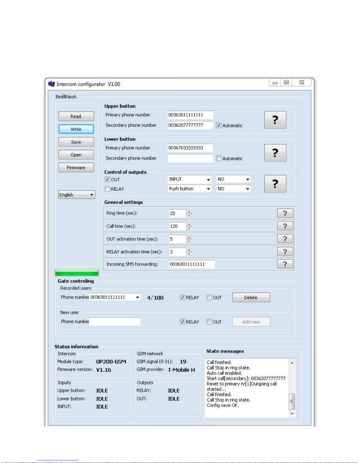
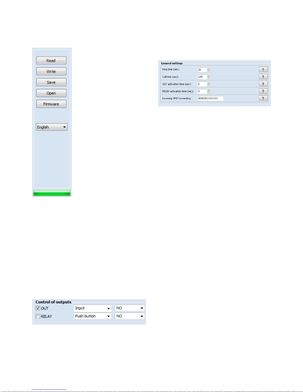
Controlling the relay output
The RELAY (normally open, NO) relay output can be
controlled as follows, depending on the usage:
controlling by free call:
on incoming call, after identifying the caller ID, the
unit rejects the call and activates the output
e.g. garage door or barrier opening, for which max
100 user phone numbers can be configured
controlling by the pushbutton:
the relay activates when the call button is pushed
e.g. possibility to connect an existing door bell
controlling by the INPUT contact input:
the relay activates on external contact
e.g. garage door opening or closing
controlling by the phone’s:
while in call by pressing 1# of the phone’s
numbered keys the relay activates for the
configured time period
ATTENTION:
The RELAY and –OUT+ outputs is activated in
parallel and independently from each other by
both menu items, the Control of outputs and the
Gate control. Please take this into consideration
when planning the usage!
Controlling the voltage output
The –OUT+ voltage output can be controlled as
follows:
controlling by the INPUT contact input:
after activating the input, the output activates for
the configured time period
e.g. optional indoor pushbutton for electric lock
control
controlling by the phone’s keys:
while in call by pressing 2# of the phone’s
numbered keys the output activates for the
configured time period
e.g. direct control of the electric lock
The voltage output is protected against short circuit
and overcurrent, thereby the output turns off upon
overcurrent and becomes operable again after the
termination of the fault.
Forwarding incoming SMS messages
The unit forwards the SMS messages received on its
SIM card (e.g. balance information in case of a
prepaid card) to the configured phone number. After
forwarding, the received message is deleted from the
SIM card. If there is no phone number configured, the
unit deletes the incoming messages without
forwarding.
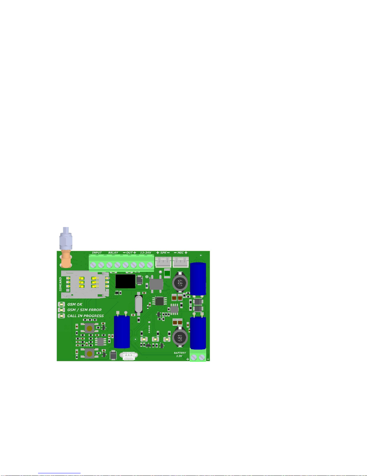
Status LED indications
LED
Color
GSM OK
green
Is lit after connecting to the
GSM network and reaching
the sufficient GSM signal.
The sufficient signal is: 10
(on 0-31 scale)
GSM / SIM
ERROR
red
Is lit continuously if the device
cannot connect to the GSM
network.
Possible reasons:
- the GSM antenna is faulty or
is not connected
- the SIM card is not inserted,
- or the PIN code request is
not disabled,
- or the SIM card is faulty.
CALL IN
PROGRESS
green
Communication in progress.
A call or conversation is in
progress.
-OUT+
red
Voltage output activated
RELAY
red
Relay output activated

UP200-GSM Rev.1.2 08/01/2014
SETTING WITH MS WINDOWS APPLICATION
The intercom unit parameters (phone numbers, controls) can be configured using the Intercom configurator
software found on the internal storage of the device. You can run the program directly from the unit’s drive after
connecting to USB (Widows XP and Windows 7 compatible).

UP200-GSM Rev.1.2 08/01/2014
Administration operations
These menu items serve for reading, writing, saving
etc. the settings.
Buttons
The intercom unit calls the phone numbers entered
here when the appropriate button is pressed. If both
phone numbers are set to any button, the unit calls the
primary phone number first.
In case of an unsuccessful call (e.g. if the called
number is not available or the call is not accepted),
calling the secondary phone number can be done by
pushing the button again (within 60 seconds). If the
Automatic option is enabled, then the unit calls the
secondary phone number if the primary fails without
having to push the button again.
Control of outputs
The two outputs of the unit can be controlled by
multiple configured events. You can choose the
activation event according to the usage.
OUT
The voltage output, e.g. for direct control of an electric
lock.
RELAY
The relay contact output, e.g. for garage door control.
You can select the activation event and the normal
state of the output (idle state) from the drop-down
menus. Upon activation, the output state changes for
the configured time period.
General settings
Ring time (10-120 sec)
The maximum time allowed for ringing from pushing
the call button. This function is useful to avoid
switching to voicemail.
Call time (10-600 sec)
The maximum time allowed for a call initiated from the
intercom.
OUT active time (1-120 sec, monostable)
The voltage output activation time.
RELAY active time (1-120 sec, monostable)
The relay contact output activation time.
SMS forward
Forwards the SMS messages received on the unit’s
SIM card to the specified phone number, e.g. balance
information received from the GSM service provider. It
is recommended to configure this in case of using a
pre-pay type SIM card.
Gate control
When calling the intercom from the phone numbers
specified here, control of the output or outputs
assigned to the given phone number is performed.
The incoming call is not accepted, thereby this
function works with free calls. Maximum 100 user
phone numbers can be added.
Status information
Displays information about the switching state of the
peripheries and the actual status of the mobile
network.
State messages
The messages shown in this window give information
about the internal operation of the unit. This helps in
identifying an internal process, an incorrect
configuration or other malfunction.
The question marks placed next to the settings in the
Intercom configurator give assistance to the
parameter settings of the given section.
Read
Click to read and displays the
settings from the unit.
Write
Click to write the settings to the
unit’s memory.
Save
Click to save the settings to file.
Open
Click to open saved settings
from file.
Firmware
Click to update the intercom’s
firmware.
English/Magyar
Click to change the Intercom
configurator’s interface
language.
Progress bar

UP200-GSM Rev.1.2 08/01/2014
SETTING WITH SMS COMMANDS
Configuration of the unit is possible by sending the appropriate commands in SMS to the module’s phone number. It
is possible to send more commands (settings) in the same SMS, but the length of the message must not exceed 140
characters! Each message must begin with the password using the PWD=password#command and each command
must end with #character, else the module does not apply the modifications. The following table contains the
configuring and query commands:
Configuration commands
PWD=1234#
Password for programming, default setting:1234
PWC=new password #
Changing the password. The password is a 4-digit number.
RESET#
Resetting the settings and the password to default.
UPTEL1=phone number#
Primary phone number for upper pushbutton.
UPTEL2=phone number#
Secondary phone number for upper pushbutton.
UPAUTO=ON# vagy OFF#
In case the call to UPTEL1 fails, UPTEL2 phone number will be called
without having to push the button again, if the parameter is ON.
LOWTEL1=phone number#
Primary phone number for lower pushbutton.
LOWTEL2=phone number#
Secondary phone number for lower pushbutton.
LOWAUTO=ON# or OFF#
In case the call to LOWTEL1 fails, LOWTEL2 phone number will be called
without having to push the button again, if the parameter is ON.
OUT=activation event#
Voltage output control: OFF: disable, BUTTON: when button is pressed
INPUT: when input is activated, PHONE: during call, pressing any of the
phone’s keys, IN+PHONE: INPUT and PHONE enabled
RELAY=activation event#
Relay control: OFF: disable, BUTTON: when button is pressed
INPUT: when input is activated
RINGTIME=duration#
Ringing time of the telephone to restrict the reach of voice mail. (10-120sec)
CALLTIME=duration#
Maximum duration of the conversation. (10-600 sec)
RTIME=duration*NO# or NC
Duration and idle mode of the relay output activation. (1-120 sec)
OUTTIME=duration*NO# or NC
Duration and idle mode of the voltage output activation. (1-120 sec)
RTEL=phone number*REL*OUT#
Setting the phone numbers for relay or voltage output activation. For output
activation the suffix after the phone number is necessary.
*REL: switch the realy, *OUT: switch the voltage out,
*REL*OUT switch both. Up to 100 users.
RTELDEL=phone number#
Delete the selected phone number.
STATUS?#
Query of the settings except RTEL list.
RTEL?#
Query of the RTEL list.
INFOSMS=phone number#
Forwards the incoming SMS messages.
This scenario shows the configurations for the following requirements: phone number 2 only for upper pushbutton,
auto switch to the secondary phone, VOUT control (for electric lock) by phone and input contact, duration is 10sec,
both phone numbers are able to control the gate control’s relay by a free call, relay activation time is 5sec.
Other call parameters: Ringingtime=25sec; maximum duration of the conversation=120sec; forwarding prepaid card
information to primary phone number
SMS message:
PWD=1234#UPTEL1=0036309999999#UPTEL1=0036201111111#UPAUTO=ON#OUT=IN+PHONE#
OUTTIME=10*NO#RTEL=0036309999999*REL#RTEL=0036201111111*REL#RTIME=5*NO#
RINGTIME=25#CALLTIME=120#INFOSMS=0036201111111#

UP200-GSM Rev.1.2 08/01/2014
INSTALLATION
Mounting
Measure the GSM signal with your mobile phone. It
may happen that in the desired place of installation
the signal strength is not satisfactory. In this case
you can move the unit or the GSM antenna in a
more suitable place before installation.
Do not mount the unit where it could be affected by
strong electromagnetic disturbances.
Antenna: the GSM antenna supplied with the unit
provides good transmission under normal reception
circumstances. In case of having signal strength
problems and/or noisy communication, use other
type of higher gain antenna or find a more suitable
place for the antenna.
Inserting the SIM card: pull the metallic part of the
SIM case towards the center of the panel to open up
the SIM slot for inserting the card. Insert the SIM
card into the slot so that its contact surface should
point towards the contact pins of the card case
when turned down, as well as the cut corner of the
card should fall towards the edge of the panel, in the
direction of the LEDs. Fasten the SIM card by
pulling back the metallic part of the SIM case.
Connection diagram
Putting into operation
Disable PIN code request, voicemail and missed
call notification service on the SIM card.
Enable caller identification and caller ID sending
service on the SIM card at the GSM service
provider.
Make sure the SIM card is inserted properly into its
case.
Make sure the antenna is fixed properly into the
SMA connector.
Make sure the wires are connected as shown in
the connection diagram.
Make sure the power supply is sufficient for the
operation of the unit! If it is, and all connections are
done, the unit can be powered up.
If operated without an electric lock from a 16V AC
transformer, the current requirement is 300mA
(5VA).
When operated with an electric lock, the
minimum power requirement is 20VA!
① ②③④⑤⑥⑦
⑪ ⑩ ⑨ ⑧
⑬
⑫
①GSM antenna connector
②Contact input
③Relay contact output
④Voltage output
⑤Power input
⑥Speaker output
⑦Microphone input
⑧Battery connector
solar powered version only!
⑨Name plate lighting
⑩USB mini B port
⑪Call pushbuttons
⑫Status LEDs
⑬SIM card case

UP200-GSM Rev.1.2 08/01/2014
EXTRA FUNCTIONS
With the help of lang.ini which contains the Intercom configurator’s settings the below settings can be done:
Changing audio settings
SpkAnalog= volume (0-70), default value: 30
MicAnalog= michrophone sensitivity (0-13), default value: 10
Attention: By changing the above values echoing can increase!
Backlight brightness
Light= brightness (0-10), default value: 5
After changing the settings and saving lang.ini it is necessary to run Intercom configurator program again and to
upload the new settings on the module to validate the changes.
TECHNICAL SPECIFICATION
Name
Other conditions
Minimum
Typical
Maximum
Unit
Power supply
DC mode
12
16
34
VDC
AC mode
12
14
24
VAC
Current consumption
for 16VDC
40
50
400
mA
Relay output load
DC switching
24
V
1
A
AC switching
125
V
0.5
A
Voltage output
11.5
12
13
V
1
A
Contact input switching
0
0
100
Ohm
Operating temperature
-30
+60
°C
Outdoor protection
IP54
Package contents
UP200-GSM
GSM 900MHz / 1800MHz antenna
Antenna bracket + fixing screws
Other data
Transmission frequency GSM850 / EGSM900
DCS1800 / PCS1900
Dimensions height:165mm
width:122mm
depth: 40mm
Table of contents