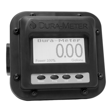
DURA DURA-METER DP-HFM2 User manual

3” HIGH-FLOW DURA-METER™
INSTALLATION GUIDELINES
This page details mounting and installation guidelines for the Dura-Meter®
High Flow paddle wheel meter. These are location and installation guidelines.
This is not a troubleshooting guide for mechanical/electrical issues.
About 95% of the ow metering issues are
traceable back to the following 5 simple principles.
THE FLOW RATE MUST BE WITHIN THE RECOMMENDED RANGE
FOR THE PIPE SIZE THE METER IS INSTALLED ON.
All ow meters all have a minimum ow rate they will measure for each pipe size. No ow meter
reads down to 0. This lower limit is a result of the ow velocity not containing enough momentum
to keep the paddle wheel spinning. At some point the ow velocity drops and the paddle no longer
spins linearly with respect to the ow rate. This is the lowest ow rate the meter can accurately
measure. The meter may indicate ow rates below this value but will contain a large inaccuracy. At
some point the ow velocity becomes too low and the meter will indicate 0, even though there is
still ow.
The bottom line – if you don’t have an adequate ow rate you need to either reduce the pipe
diameter or nd a different ow meter. You won’t get satisfactory results trying to monitor ows
below the recommended minimum value.
1
HFM3_Assembly_Installation_120623
3” HIGH-FLOW DURA-METER™
QUICK ASSEMBLY INSTRUCTIONS
1
2
3
4
5
Connect paddle wheel circuit wire to faceplate
Connect the (2) 9V batteries
Install 9V batteries into meter body
Install the (4) 10-32 bolts and slightly snug
to tightness
Secure face plate to meter body
and ensure you do not pinch any cables

THE PIPE MUST BE FULL OF FLUID AT ALL TIMES
The pipe must be completely full of liquid! This is particularly an issue when the meter is installed on
pipes that have a downward ow direction. Vertical pipes with a downward ow are the most prone
to this issue. Huge ow variations can be noted on the meter if the pipe isn’t full. On horizontal runs
with partially lled pipes the results will be either no ow reading if the paddle isn’t in the ow path
due to the meter paddle wheel being mounted on top of the pipe, or readings that are mysteriously
high or erratic. If keeping the pipe uid full is a challenge, a partially closed valve downstream will
restrict the ow and keep the pipe full.
THERE MUST BE A SUFFICIENT LENGTH OF STRAIGHT PIPE
BEFORE AND AFTER THE METER.
To develop a uniform ow prole in the pipe, a sufcient straight section of pipe must be both
upstream and downstream of the meter. The diagram is a general idea of necessary lengths of pipe
needed to develop uniform ow and get accurate results from the ow meter.
If an adequate run of straight pipe isn’t possible, a reduction in accuracy may result. Typically the
error is uniform (linear) across the ow range. The ow rate can be determined by meter calibration,
the ow meter can be adjusted for repeatability and thus accuracy. The instruction manual illustrates
methods for calibration.
INSTALLATION OF METER WITH
HORIZONTAL OR VERTICAL PIPE
Install ow meter at the location where the pipe is lled with liquid.
A. Horizontal Pipe
optimal option:
THE FLUID ENTERING THE METER MUST BE FREE OF DEBRIS.
A lter should be installed before the ow meter to lengthen service life and improve measurement
accuracy. The lter should be installed before the ow meter to remove impurities or foreign objects
from the uid that can interfere with the mechanical components.
2
3
4
5
Slanted upward 45o
Horizontal Pipe
Paddle
Fluid Flow Direction
B. Vertical pipe
optimal option:
>7" >7"
Pipe diameters needed to
develop uniform ow
Fluid Flow Direction

TECHNICAL SPECIFICATIONS
Nominal Size 2” 3”
Model DP-HFM2 DP-HFM3
Connection M220 ange M300 ange
Meter Accuracy +/- 0.5% +/- 0.5%
Non-conductive Fluids Ye s Ye s
Fluid Flow Initiates Measurement Ye s Ye s
Battery Size/Voltage (2) 9 Volt (2) 9 Volt
Battery Life Indicator Ye s Ye s
Backlit Display Ye s Ye s
Maximum Pressure 150 PSI 150 PSI
Minimum GPM 15 15
Maximum GPM 300 700
Minimum Temp + 32 °F + 32 °F
Maximum Temp + 140 °F + 140 °F
Meter Type/Style Paddlewheel Paddlewheel
Body Construction Material
GF Polypropylene GF Polypropylene
Paddle Bearing Construction Material Sapphire Sapphire
Electrodes Construction Material No No
Minimum Straight Inlet * 7” * 7” *
Minimum Straight Outlet * 7” * 7” *
Field Calibration Capability * Yes * Yes *
cP Viscosity Range 0-50 Centipoise 0-50 Centipoise
* Must calibrate to achieve +/- 0.5% Accuracy
The meter will turn ON with any button press
or when uid passes through the meter. It will
turn OFF when not in use.
Use buttons to navigate the four main menus;
Reset, Program, Calibration, Info. The buttons
correspond to the on screen indicators.
(2) 9 Volt batteries provide about 35 hours of
use with the backlight turned ON. Battery life
is extended with the backlight OFF.
HIGH-FLOW
DURA-METER™

NOTE: Use a primed system. Verify your calibration. Fluid viscocity changes with temperature.
CALIBRATION
QUICK
CALIBRATION
MANUAL
CALIBRATION
PREFERRED METHOD
Select a viscocity
reference number using
water as the baseline.
Check
Dispense approximately
100 gallons and verify
accuracy.
Adjust
Each viscosity reference number
represents 1% change. (i.e.) If
the meter reads high, lower the
viscosity reference number. Adjust
the value Up or Down
Repeat as needed.
/ Great for eet use / Most accurate
/ Usually only takes one attempt
/ Adjustable to compensatefor
different measurement containers
Method 1: With a Calibrated Container
Fill a calibrated container.
Method 2: Without a Calibrated Container
Fill a container that can be weighed with
approxiamtely 100 gallons. Divide the weight by uid
density to determine gallons dispensed.
Adjust
Adjust the default value Up or Down
to match the volume dispensed.
Press Save as uid
#1 - #5 and Verify!
This manual suits for next models
1
Other DURA Measuring Instrument manuals
Popular Measuring Instrument manuals by other brands

EM-Technik
EM-Technik 4Z Series Assembly and operation instructions

Siemens
Siemens US2:9810T24V user manual

janitza
janitza UMG96RM installation manual

PURGE SOLUTIONS
PURGE SOLUTIONS CYCLOPS Z quick start guide

Dimplex
Dimplex FD 9405 / L20 operating instructions

LaserLiner
LaserLiner RollPilot S6 quick start guide