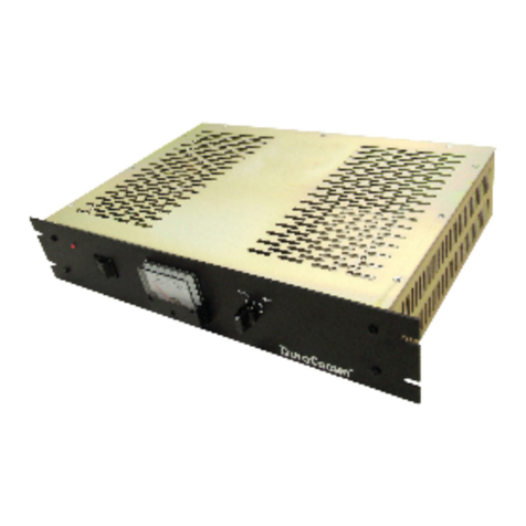
DuraComm DC-RMCU1 User manual

DC‐RMCU1
DC‐PoweredRemoteMonitoringandControlUnit
OwnersGuide
(These instructions are intended for use by a technician familiar with electronic products)
RemoteMonitoringandControlUnit
WebReady/WebGUI/MobileStatusPage
6IsolatedVoltageinputswithadjustablehighandlow
alarmthresholds.(CH1settomeasurecurrent)
4DigitalOutputs(Open‐DrainMOSFET)
4DigitalInputs
Configureemailsforalarmswithexternalemailaccount
SNMPTrapsforBoot‐upandAlarms
SNMPControlofDigitalOutputs
Remotereboot
2UserLevelswithdifferentpermissions
ManualorNTPTimeSetting
TempSensorInput(UsesLM35)
ACVoltageMonitorInput,300VAC
MonitoringSamplescanbeLoggedandDownloaded
BatterybackedupRealTimeClocktoTimestampLogged
NewLiveInformation
WideInputDCSupplyRange,9to60VDC
AccessoryKitSupplied
3yearwarranty
DESCRIPTION
The new DC-RMCU1 DC-Powered Remote Monitoring and Control Unit, provides the ability to remotely monitor AC Line
voltage up to 300 VAC, up to 6 DC Voltages and 1 temperature, monitor the status of up to 4 external alarms, as well as the ability to
remotely control the state of 4 digital open-drain MOSFET outputs, all via the internet using any standard web browser. The Channel 1
DC voltage input is configured at the factory to measure current using the included 100 Amp/50mV shunt. Additional channels can be
configured at the factory for current measurement. A mobile friendly version of the status page is also included. Alarms and email
notifications can be configured for the 6 analog voltage channels (high and low voltage), and email notifications can be configured for
the Alarm inputs. A high-temperature alarm threshold can be configured to send an email notification, as well as control one of the
digital outputs internally. The DC-RMCU1 also sends SNMP Traps for alarm conditions. The DC-RMCU can also be set to log
measurements to a 2 GB internal micro SD card, and the measurements are time-stamped with a real-time clock.
Guest users will see the status page that displays the AC Voltage, measured values and alarm condition of all active voltage
channels, temperature value and alarm condition, as well as alarm input status, and control status.
Admin and Control Users will be able to configure all of the input and output settings, and set the state of the digital outputs.
Admin and Control users can set device settings for logging, time, and Site Name.
Admin users have exclusive control of network configuration, including manual time setting or NTP, soft reboot of the DC-
RMCU1, factory reset of the entire configuration, and Control or Admin user passwords.
The DC-RMCU1 comes with the DuraComm three-year warranty.

2 of 32 January 20, 2016

3 of 32 January 20, 2016
TABLE OF CONTENTS
DESCRIPTION....................................................................................................................................................................................................................0
SPECIFICATIONS................................................................................................................................................................................................................4
AccessoryKit(Included)....................................................................................................................................................................................................4
INSTALLATION..................................................................................................................................................................................................................5
InputPower.................................................................................................................................................................................................................5
10/100Ethernet...........................................................................................................................................................................................................5
DCRMUBoardLayoutandConfiguration....................................................................................................................................................................6
ConnectingTOTheDC‐RMCU1VIAtheInternet..............................................................................................................................................................8
Prerequisites................................................................................................................................................................................................................8
DeterminingtheIPAddressoftheDC‐RMCU1.................................................................................................................................................................8
UsingDHCP..................................................................................................................................................................................................................8
UsingStaticDC‐RMCU1IPandNetworkConfiguration...............................................................................................................................................8
OpenaWebConnectiontotheDC‐RMCU1................................................................................................................................................................9
REMOTEMonitoringandControlSetup.........................................................................................................................................................................10
UserLogin..................................................................................................................................................................................................................10
NetworkSetup................................................................................................................................................................................................................11
NetworkSetupNotes.................................................................................................................................................................................................11
SNMPTrapsSetup..........................................................................................................................................................................................................12
EmailSetup.....................................................................................................................................................................................................................13
EmailSetupNotes......................................................................................................................................................................................................13
DeviceSetup...................................................................................................................................................................................................................14
DeviceInfo.................................................................................................................................................................................................................15
Logging.......................................................................................................................................................................................................................15
DateandTimeSettings..............................................................................................................................................................................................15
MiscellaneousSettings..............................................................................................................................................................................................15
SensorSetup...................................................................................................................................................................................................................16
SensorSetupNotes....................................................................................................................................................................................................17
SensorCalibration..........................................................................................................................................................................................................18
SensorCalibrationNotes...........................................................................................................................................................................................19
AnalogandDigitalWiring...............................................................................................................................................................................................20
ACLineVoltageMeasurement..................................................................................................................................................................................20
AnalogChannels:DCVoltageMeasurement............................................................................................................................................................20
AnalogChannels:DCAmperageMeasurement.........................................................................................................................................................21
TemperatureMeasurement......................................................................................................................................................................................21
SensorSetup–DigitalInputs(Alarms).......................................................................................................................................................................22
SensorSetup–DigitalOpen‐DrainOutputs...............................................................................................................................................................23
AlarmSetup....................................................................................................................................................................................................................24
AlarmSetup...............................................................................................................................................................................................................25
FactoryDefaultAlarmSettings..................................................................................................................................................................................25
UserSetup......................................................................................................................................................................................................................26
UserSetupNotes.......................................................................................................................................................................................................27
REMOTEMonitoringandControlstatuspage................................................................................................................................................................28
Statusscreen..............................................................................................................................................................................................................28
MOBILESTATUSSCREEN................................................................................................................................................................................................29
RMCUMaintenance.......................................................................................................................................................................................................29
Battery.......................................................................................................................................................................................................................29
CONDUCTORPRETREATMENT........................................................................................................................................................................................30
RECOMMENDEDCOPPERWIRESIZEFORCURRENTCAPACITY......................................................................................................................................30
LIMITEDWARRANTY.......................................................................................................................................................................................................32

4 of 32 January 20, 2016
SPECIFICATIONS
Hardware Revision...........................................................................................................................................................................2.0
Firmware Revision............................................................................................................................................................................2.4
DC Input Power........................................................................................................................................9 to 60 VDC @ 500 mA max
Internal +5VDC supply current (Source for external Logic)...............................................................................................300 mA Max
Voltage Input Channels (6 channels) – Max Voltage ........................(Internally Isolated) +/-2 V with jumper, +/-100 V without jumper
Digital Alarm Input Channel Thresholds (4 channels) ..........................LED with 220 Ohm Series Resistor, 50 mA Max (per channel)
Digital Output (4 Channels)..................................................................Open Collector, 60 VDC Max, 500 mA sink Max (per channel)
Network Connector.............................................................................................................RJ-45 (10/100 Ethernet) with activity LEDs
Terminal Connector........................................................................................................................................(factory diagnostics only)
Backup Battery (for Real Time Clock)......................................................................................................................................CR2032
Memory Card .......................................................................................................................................................... 2GB min Micro SD
Voltage Measurement Range..................................................................................................................................0 VDC to 100 VDC
Current Measurement Range...............................................................................................................................0 Amps to 100 Amps
Alarm Response Time................................................................................................................................................................ 250ms
Alarm Notifications .................................................................................................................................................Email and/or SNMP
Logging Rate............................................................................................................................1 minute resolution, 1 minute to 1 hour
Log Download Format................................................................................................................Comma Separated Values (CSV) File
Temperature Measurement Range using LM35 connection (J8) .....................................................+36 F to +300 F (+2 C to +150 C)
Working Temperature Range.............................................................................................................-22 F to +140 F (-30 C to +60 C)
Storage Temperature.........................................................................................................................-40 F to +185 F (-40 C to +85 C)
Dimensions .............................................................................................................................................................. 8”H x 3.2”W x 5”D
Weight........................................................................................................................................................................................1.7 lbs.
ACCESSORY KIT (INCLUDED)
Ethernet Cable.............................................................................................................................................................................3 feet
Current Measurement Shunt..................................................................................................................................... 100 Amp / 50 mV
Temperature Sensor ....................................................................................................................................................................LM35
Rubber Feet........................................................................................................................................................................................4
Wall Mounting Bracket ................................................................................................................2 brackets and 4 sheet metal screws

5 of 32 January 20, 2016
INSTALLATION
Input Power
TheDC‐RMCU1DCPWRconnectionsonthepowerstrip.Pleasebesuretoconnectthepositiveterminaltothe
positive(+)supplylead,andthenegativeterminaltothenegative(‐)supplylead.Thesupplyvoltagemaybe9VDCto60
VDC.
NOTE:TheDC‐RMCU1is“ON”assoonaspowerisapplied.
10/100 Ethernet
ConnecttheRJ‐45ontheDC‐RMCU1toyournetworkwithanEthernetpatchcable.Ashort3footcableisprovidedwith
theDC‐RMCU1.
NOTE:TheUSBconnectorisforfactorydiagnosticsonly.

6 of 32 January 20, 2016
DCRMU Board Layout and Configuration
Figure1:PCBLayout
TheDC‐RMCU1comeswithajumperinstalledonP1toconfigureanalogchannel1for+/‐2Vtomeasurecurrentshunt
voltage.
SeetheSensorSetupSectionforsensorwiringandconfiguration.
Figures2and3ShowconnectorwiringfortheDC‐RMCU1inputsfortroubleshootingpurposes.

7 of 32 January 20, 2016
Figure2:J1andJ3Wiring
Figure3:J2Wiring

8 of 32 January 20, 2016
CONNECTING TO THE DC-RMCU1 VIA THE INTERNET
Prerequisites
SystemadministratorsmustdecidewhethertheDC‐RMCU1willoperateonthenetworkwithDHCPorafixedIPaddress.
Thefactory‐setDC‐RMCU1willhavethesestaticaddresses:IPaddress:192.168.100.220,gatewayaddress:
192.168.100.1,netmask:255.255.255.0,andDNSaddress:192.168.100.1.
IfyouconfigureittouseDHCP,theDC‐RMCU1willrequestanavailableIPaddressonyournetwork.Youwillneedto
determinewhataddressithasbeengiven.
IfDHCPisnotused,systemadministratorsmustalsochooseanunusedIPaddress,andothernetworksettingstousein
theNetworkSetupscreen.Systemadministratorswillalsoneedtochooseanemailserviceandaddresstousefor
notifications,ifneeded.ThesewillbeusedintheEmailSetupScreen.
DETERMINING THE IP ADDRESS OF THE DC-RMCU1
PoweruptheDC‐RMCU1thenconnecttheDC‐RMCU1tothenetworkwithanEthernetcable.A3footcableisprovided.
Using DHCP
TheDC‐RMCU1willattempttoconnecttothenetworkviaDHCPwhenitisfirstconnected,orwhenyouperforma
factoryreset.
YouwillneedtogettheIPaddressinoneoftwoways.YoucangettheIPaddressfromtheDHCPserver’sclientlist,or
youcanuseaPConthesamenetworktoscanforthenewIPaddressbyusingasoftwaretoolsuchasAngryIPScanner.
InAngryIPScanner,youshouldaddtheMACaddress“Fetcher”under“Tools>Fetchers”.TheDuraCommMAC
addressesallstartwithabaseaddressof70‐B3‐D5‐6B‐3.WritedowntheIPaddressoftheDC‐RMCU1,then
proceedtothesectioninthismanualnamed“OpenaWebConnectiontotheDC‐RMCU1”.
Using Static DC-RMCU1 IP and Network Configuration
IfyournetworkisnotsetupforDHCP,youwillneedtomanuallyconfigurethesettingstomatchthenetworkitwillbe
usedon.Beforeyoucandothat,youwillneedtoconfigureacomputertotalktotheDC‐RMCU1atthedefault
configurationsettingsshownabove.WewilluseWindows7asanexample.Otheroperatingsystemswillvary,butthe
overallconceptisthesame.
1. DisconnectyourPCfromallnetworks.
2. ConnectitdirectlytotheDC‐RMCU1withanEthernetcable(YoumayneedtouseanEthernetcrossovercableifthePC
doesnotautomaticallydetectthisconfiguration).
3. OpenthecontrolpanelonyourPCandselect“ViewNetworkStatusandTasks”
4. Clickon“ChangeAdapterSettings”ontheleftsideofthescreen.
5. Rightclickon“LocalAreaConnection”andclickon“Properties”
6. Clickon“InternetProtocolVersion4(TCP/IPv4)”tohighlightit,thenclickthe“Properties”button.
7. Beforeyoumakeanychanges,recordtheexistingsettings,sothatyoucanchangethembackwhenyouarefinishedsetting
uptheDC‐RMCU1.
8. Enable“UseTheFollowingIPAddress”
9. Nowenter192.168.100.221fortheIPaddress.
10. Enter255.255.255.0Subnetmask
11. ClickOKtosavethenetworkconfiguration.
12. Jumptothesectioninthisownersguidenamed“OpenaWebConnectiontotheDC‐RMCU1”tologinandenterthefinal
networksettingsfortheDC‐RMCU1.

9 of 32 January 20, 2016
Open a Web Connection to the DC-RMCU1
Useyourfavoritedeviceandbrowser(Chrome,Firefox,internetExplorer,etc.),andentertheIPaddressofthe
powersupplyonyournetworkintotheURLboxonthebrowser(seethescreenshotbelow).TheDC‐RMCU1should
respondwiththe“Status”screen.

10 of 32 January 20, 2016
REMOTE MONITORING AND CONTROL SETUP
Click “Network Setup” in the menu at the top of the screen. All setup requires an administrative user to log into the DC-RMCU1. See
default passwords below.
User Login
Enter the user name and password. Factory default username and password are as follows:
Admin Users have full control of the device.
Username: admin (cannot be changed)
Password: admin
Control users have limited control capability.
Username: control (cannot be changed)
Password: control
These two users are the only ones available in the DC-RMCU. “Control” users can access all screens except the User Setup screen.

11 of 32 January 20, 2016
NETWORK SETUP
Network Setup Notes
Anetworkadministratorforyourcompanymustchoosethesettingsforthispage.ThedefaultHTTPportis80.Ifa
differentHTTPportisused,itwillneedtobeaddedtotheURLtoaccesstheRMCU.Forexample:iftheportischanged
to8080thentheaddresswouldbechangedtohttp://192.168.0.253:8080
NOTE:Youmustrebootthedeviceforchangesinthesesettingstotakeeffect.

12 of 32 January 20, 2016
SNMP TRAPS SETUP
Thissectionissimplified,andmeantfornetworkadministratorswhoalreadyunderstandSNMPtrapsandhowto
configurecapableequipmentintotheirsystem.ForthosewhowanttounderstandthebenefitsofusingSNMPtraps,
youcansearchfortrainingmaterialonlineunder“SNMPTraps”,“MIBBrowsers”,and“SNMPMonitoring”.
TheMIBfilefortheDC‐RMCU1canbedownloadedfromtheDC‐RMCU1afteryouconnecttoitwithyourbrowser.Goto
theDeviceSetuppageandlogintotheDC‐RMCU1.HalfwaydownthepagethereisalinktotheMIBfile.Rightclickon
thelinkandclick“SaveLinkAs”todownloadthefile.
Afterdownload,importtheMIBfileintoyourMIBbrowserorMonitoringsoftwaretoconfigureitforusewiththeDC‐
RMCU1.
WhentheMIBfilehasbeenloaded,completethe“SNMPSetup”sectiononthe“NetworkSetup”pageoftheDC‐RMCU1
toconfigureitforusewithyourmonitoringsolution.
TheDC‐RMCU1willsendtrapsforallconfiguredalarmconditionsincludingbootup,temperature,analogalarms,and
digitalalarms.

13 of 32 January 20, 2016
EMAIL SETUP
Email Setup Notes
EntertherequiredemailsetupparametersgiventoyoubyyourSystemAdministrator.Youcanalsosendatestemail
fromthisscreen.TheexampleshowshowtosetupaGmailaccountconnection.Note:theGmailaccountneedstobe
set2‐stepauthorization“Off”.LogintotheGmailaccount,gotoaccountsettings,gotothe“SigningIn”section,and
verifythat2‐stepauthorizationis“Off”.

14 of 32 January 20, 2016
DEVICE SETUP

15 of 32 January 20, 2016
Device Info
Acustomsitenamecanbeenteredhere,andthemodelnumber,serialnumber,softwareversion,andhardwareversion
areshownhere.
Logging
TheDC‐RMCU1willlogallmeasurementsandalarmstoanSDcardthatispluggedintotheDC‐RMCU1board.Userscan
settheratehere,aswellasclearthecard,orappendnewmeasurements.TheCSVlogfilecanbedownloadedhere,as
wellastheStatuspage.YoucanalsoexaminethelogfileusingaterminalconnectionthroughtheUSBport.IftheSD
cardfillsup,theoldestsampleisdiscardedwhenanewoneisstored.TheDC‐RMCU1customdevicenameisstoredwith
theloggeddata,sothatthesourceofthecardcanbeidentifiedafteritremovedfromtheRMCU.
ADC‐RMCU1connectedtoabatterybackuppowersystemcanmonitorandloginformationaboutACmainspower
outages,aswellasalltheothermeasurementsforaslongasthebatterybackuplasts.
Whenalogfilereaches5MB,itisrenamed,andanewoneisstarted.Downloadalllogfilesbeforeclearingthelog.
WithREV2.4Firmware,theDC‐RMCU1hastheabilitytosavelogentrieswhenanalarmoccursbychoosing“Log
Alarms”>“Yes”.Youcanlogalarms,logperiodicallybysettingthe“LoggingRate”minutes,logboth,orlognoneby
choosing“LogAlarms”>”No”andsettingthe“LoggingRate”to“0”.TheAlarmlogentryisidentifiedwithlabelentry
beforethedataentry,asinthisexample:
Date and Time Settings
Configurationforalldateandtimesettings.Dateandtimeisbatterybackeduponthecard,andthevaluesaresavedin
theloggedsamples.Thereal‐time‐clockcansynchronizeit’stimetothenetworkthroughanNTPserver,oritcanbeset
manuallyifanetworkisnotavailable.
TheNISTNTPserverscanbeusedbyentering
time.nist.govorpool.ntp.org,
oranotherNTPserveraddress
into
the
NTPServerbox.
Miscellaneous Settings
Thenumberofsignificantdigitstotherightofthedecimalpointfortheanalogchannelscanbeconfiguredhere.Note:
Bestresolutionisabout1in1000.
TemperaturecanbeconfiguredtoreadinFahrenheitorCelsius.
.

16 of 32 January 20, 2016
SENSOR SETUP

17 of 32 January 20, 2016
Sensor Setup Notes
Theadminusercansetcustomnamesforeachinputoroutput.Factorysetnameswillbesupplied,buttheycanbere‐
writtentobemoredescriptive,ortomanagelargersystems.Alarmcolorscanbesetheretorepresenttheproper
logicalstateforyoursystem.Ifanyofthenamefieldsontheleftareleftblank,thechannelwillbehiddenonthestatus
screen.
DigitalOutputscanbeuser‐configuredtomatchyourcircuit.“Active”referstotheoutputMOSFETbeing“ON”or
conducting.Youmayalsoconfigureeachoutputtoprovideapositiveornegative500uSpulse.Buttoncolorsand
orientationarealsoselectable.Auser‐nameforActiveandInactivestatescanalsobeconfigured.
Analoganddigitalalarmsaresetupinthe“AlarmSetup”screen.Seethe“AlarmSetup”sectionformoreinformation.

18 of 32 January 20, 2016
SENSOR CALIBRATION

19 of 32 January 20, 2016
Sensor Calibration Notes
SensorcalibrationsisprovidedtoconvertthenativevoltagemeasurementsoftheDC‐RMCU1intootherunitsforlinear
transducers.Forexample,thecurrenttransducerprovidedwiththeDC‐RMCU1willhave50mvacrossitwhen100Amps
isflowingthroughit.Theconversionfactorisenteredonthispage.
Channelsthatonlymeasurevoltagedonotneedaconversionfactor,andtheentriescanbeleftat0.Whenaphysical
jumperisplacedonchannel1,itischangedfroma+/‐100Voltmaxrangetoa+/‐2Vmaxrangetogainresolutionfor
smallervoltages.The“Jumpered”drop‐downmustbesetto“Yes”forachannelwithajumpersothatitisscaled
properly.Sinceacurrentshuntisdesignedforatypicalvoltagedropof50mvatfullscale,Channel1isconfiguredwitha
physicaljumper,the“Jumpered”dropdownissetto“Yes”,andcalibrationfactorsareentered.Since0vwillbeequalto
0Amps,wedon’tneedtochangethelowerleftcalibrationfactors.Wechangetheverticalmaximumto0.05VDC
(50mv)andthehorizontalmaximumto100.Wethentype“Amps”astheuserunits.
Bydefining2pointsonthelineargraph,wecancalibrateanylineartransducer,withinthevoltagemeasurementrange
oftheDC‐RMCU1.Thiswillallowyoutouseabroadrangeofexistingtransducerstomeasuremanydifferentthingslike
pressure,temperature,force,etc.Even4‐20matransducerscanbeusedbymeasuringthevoltageacrossaresistor
placedinserieswiththetransducer.Thesetransducersrequirethatboththelower‐leftandupperrightcalibration
pointsbeconfiguredonthegraph.

20 of 32 January 20, 2016
ANALOG AND DIGITAL WIRING
AC Line Voltage Measurement
Figure4
Analog Channels: DC Voltage Measurement
Figure5
DC‐RMCU1
+12V
L
N
FG
L
FG
NUsersACVoltage
300VACMax
Table of contents
Other DuraComm Control Unit manuals
Popular Control Unit manuals by other brands

Sony
Sony HDCU4300 Operation manual

Kallista
Kallista P23052-CR installation instructions

IDT
IDT ZWIR451 Series Programming guide

American Standard
American Standard SELECTRONIC 605XTMV1070 installation instructions

Atest Gaz
Atest Gaz Sigma MOD DRV user manual

DH Instruments
DH Instruments CONSTANT VOLUME VALVE installation instructions