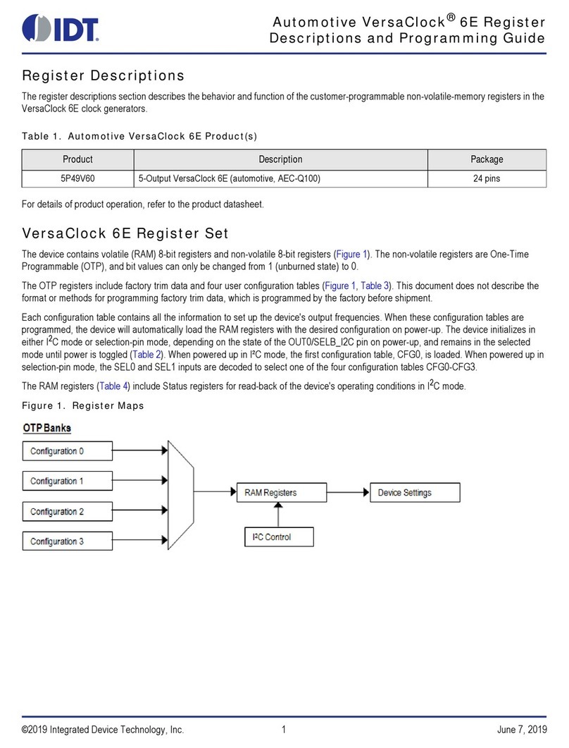
IDT ZWIR451 Series Operating instructions

ZWIR451x Programming Guide
© 2016 Integrated Device Technology, Inc.
1
April 12, 2016
Content
1Introduction.........................................................................................................................................................5
1.1. IPv6..............................................................................................................................................................6
1.2. 6LoWPAN....................................................................................................................................................6
1.3. Organization of this Document....................................................................................................................6
2Functional Description........................................................................................................................................7
2.1. Requirements Notation................................................................................................................................7
2.2. Terms...........................................................................................................................................................7
2.3. Naming Conventions ...................................................................................................................................8
2.4. Library Architecture .....................................................................................................................................8
2.5. Operating Modes.........................................................................................................................................9
2.5.1. Device Mode .........................................................................................................................................9
2.5.2. Gateway Mode....................................................................................................................................10
2.5.3. Sniffer Mode........................................................................................................................................10
2.6. Operating System......................................................................................................................................11
2.6.1. Initialization .........................................................................................................................................11
2.6.2. Normal Operation................................................................................................................................11
2.6.3. Power Modes......................................................................................................................................13
2.6.4. Error Handling.....................................................................................................................................14
2.7. Firmware Version Information ...................................................................................................................14
2.7.1. Vendor ID............................................................................................................................................15
2.7.2. Product ID ...........................................................................................................................................15
2.7.3. Major Firmware Version......................................................................................................................15
2.7.4. Minor Firmware Version......................................................................................................................15
2.7.5. Firmware Version Extension...............................................................................................................15
2.7.6. Library Version....................................................................................................................................15
2.8. Addressing.................................................................................................................................................15
2.8.1. Address Types....................................................................................................................................16
2.8.2. IPv6 Addresses...................................................................................................................................16
2.8.3. IPv6 Address Auto-configuration ........................................................................................................18
2.8.4. Validation of Address Uniqueness......................................................................................................18
2.9. Data Transmission and Reception ............................................................................................................20
2.9.1. User Datagram Protocol .....................................................................................................................20
2.9.2. Data Transmission and Reception......................................................................................................20
2.9.3. Address Resolution.............................................................................................................................22
2.9.4. Recommendations..............................................................................................................................23
2.10. Mesh Routing.............................................................................................................................................23
2.10.1. Multicast Traffic...................................................................................................................................24
2.10.2. Unicast Traffic.....................................................................................................................................24
2.10.3. Mesh Routing Parameter Configuration Recommendations ..............................................................24
2.11. Network and Device Status .......................................................................................................................26

ZWIR451x Programming Guide
© 2016 Integrated Device Technology, Inc.
2
April 12, 2016
2.12. Security......................................................................................................................................................26
2.12.1. Internet Protocol Security (IPSec).......................................................................................................27
2.12.2. Internet Key Exchange Version 2 (IKEv2) ..........................................................................................28
2.12.3. Recommendations..............................................................................................................................28
2.13. Firmware Over-the-Air Updates.................................................................................................................28
2.13.1. Functional Description ........................................................................................................................29
2.13.2. Firmware Constraints..........................................................................................................................30
2.14. Memory Considerations.............................................................................................................................30
2.14.1. Call Stack............................................................................................................................................31
2.14.2. IDT Network Stack Dynamic RAM Requirements ..............................................................................31
2.14.3. Using Dynamic Memory Allocation.....................................................................................................32
2.15. Supported Network Standards ..................................................................................................................33
3Core-Library Reference....................................................................................................................................36
3.1. Initialization................................................................................................................................................36
3.2. Program Control ........................................................................................................................................37
3.3. Networking.................................................................................................................................................41
3.3.1. Address Management.........................................................................................................................41
3.3.2. Socket and Datagram Handling..........................................................................................................44
3.3.3. Radio Parameters...............................................................................................................................49
3.3.4. Gateway Mode Functions ...................................................................................................................51
3.3.5. Miscellaneous .....................................................................................................................................52
3.4. Power Management ..................................................................................................................................55
3.5. Firmware Version Information ...................................................................................................................59
3.6. Properties and Parameters........................................................................................................................60
3.7. Error Codes ...............................................................................................................................................61
4UART Library Reference..................................................................................................................................62
4.1. Symbol Reference.....................................................................................................................................62
4.2. Custom UART I/O Configuration...............................................................................................................64
4.3. Error Codes ...............................................................................................................................................65
5GPIO Library Reference...................................................................................................................................66
5.1. Symbol Reference.....................................................................................................................................66
6IPSec Library Reference..................................................................................................................................71
6.1. Symbol Reference.....................................................................................................................................71
6.2. Error Codes ...............................................................................................................................................74
7IKEv2 Library Reference..................................................................................................................................75
7.1. Symbol Reference.....................................................................................................................................75
7.2. Library Parameters....................................................................................................................................76
8Over-the-Air Update Library.............................................................................................................................77
8.1. Library Reference......................................................................................................................................77
8.2. Inclusion of the OTAU Library ...................................................................................................................79
8.3. Error Codes ...............................................................................................................................................80

ZWIR451x Programming Guide
© 2016 Integrated Device Technology, Inc.
3
April 12, 2016
9NetMA Libraries................................................................................................................................................81
9.1. NetMA1 Library..........................................................................................................................................81
9.1.1. NetMA1 Library Symbol Reference ....................................................................................................81
9.1.2. Inclusion of the NetMA1 library...........................................................................................................86
9.2. NetMA2 Libraries.......................................................................................................................................87
9.2.1. NetMA2 Library Symbol Reference ....................................................................................................87
9.2.2. Inclusion of the NetMA2 Libraries.......................................................................................................88
10 Accessing Microcontroller Resources..............................................................................................................89
10.1. Internal Microcontroller Configuration .......................................................................................................89
10.2. Backup Data Registers..............................................................................................................................89
10.3. Interrupt Handlers......................................................................................................................................89
10.4. Default I/O Configuration...........................................................................................................................92
11 Certification.......................................................................................................................................................96
11.1. European R&TTE Directive Statements....................................................................................................96
11.2. Federal Communication Commission Certification Statements................................................................96
11.2.1. Statements..........................................................................................................................................96
11.2.2. Requirements......................................................................................................................................96
11.2.3. Accessing the FCC ID.........................................................................................................................97
11.3. Supported Antennas..................................................................................................................................97
12 Alphabetical Lists of Symbols...........................................................................................................................98
12.1. Functions and Function-Like Macros ........................................................................................................98
12.2. Data Types ................................................................................................................................................99
12.3. Variables and Constants .........................................................................................................................101
13 Related Documents........................................................................................................................................102
14 Glossary .........................................................................................................................................................103
15 Document Revision History............................................................................................................................105
List of Figures
Figure 1.1 ZWIR451x Application Domain.............................................................................................................5
Figure 2.1 Library Architecture...............................................................................................................................9
Figure 2.2 Application Interface into the Protocol Stack in Different Operating Modes.......................................10
Figure 2.3 IPv6 Unicast Address Layout..............................................................................................................17
Figure 2.4 IPv6 Multicast Address Layout ...........................................................................................................17
Figure 2.5 Resolving Address Conflicts in Local Networks .................................................................................19
Figure 2.6 Working Principle of IPSec.................................................................................................................27
Figure 2.7 Memory Layout of OTAU-Enabled Applications.................................................................................29
Figure 2.8 Heap Memory Scattering....................................................................................................................32
Figure 5.1 ZWIR_GPIO_ReadMultiple Result Alignment in ZWIR4512AC1 Devices.........................................67
Figure 5.2 ZWIR_GPIO_ReadMultiple Result Alignment in ZWIR4512AC2 Devices.........................................67
Figure 11.1 FCC Compliance Statement to be Printed on Equipment Incorporating ZWIR4512 Devices............97

ZWIR451x Programming Guide
© 2016 Integrated Device Technology, Inc.
4
April 12, 2016
List of Tables
Table 2.1 Naming Conventions Used in C-Code..................................................................................................8
Table 2.2 Event Processing Priority in the Main Event Loop..............................................................................12
Table 2.3 Power Modes Overview......................................................................................................................13
Table 2.4 Interrupts that Result in a System Reset............................................................................................14
Table 2.5 Unicast Socket Examples...................................................................................................................21
Table 2.6 Multicast Addressing Examples..........................................................................................................22
Table 2.7 Stack Parameter Dynamic Memory Size Requriements ....................................................................31
Table 2.8 Supported RFCs and Limitations........................................................................................................33
Table 3.1 Configurable Stack Parameters and Their Default Values.................................................................60
Table 3.2 Error Codes Generated by the Core Library.......................................................................................61
Table 4.1 Error Codes Generated by the UART Libraries..................................................................................65
Table 6.1 Error Codes Generated by the IPsec Libraries...................................................................................74
Table 7.1 Overview of IKEv2 Library Parameters and Properties......................................................................76
Table 8.1 Error Codes Generated by the OTAU Library ....................................................................................80
Table 10.1 STM32 Interrupt Vector Table ............................................................................................................90
Table 10.2 STM32 Default I/O Configuration........................................................................................................93

ZWIR451x Programming Guide
© 2016 Integrated Device Technology, Inc.
5
April 12, 2016
1 Introduction
This guide describes the usage of the 6LoWPAN application programming interface (API) for application devel-
opment using ZWIR451x modules. These modules provide bidirectional IPv6 communication over an IEEE
802.15.4 wireless network. Using IPv6 as the network layer protocol allows easy integration of sensor or actor
nodes into an existing Internet Protocol (IP) infrastructure without the need for additional hardware. Refer to the
data sheet for the ZWIR451x module for detailed information about the module, including pin assignments.
Figure 1.1 ZWIR451x Application Domain
Figure 1.1 shows a typical network configuration. The Personal Area Network (PAN) is built from a set of various
ZWIR451x modules. The network is connected via a border router to the local area network (LAN) and from there
to a wide area network (WAN) such as the Internet. With this setup, each module can be accessed from
anywhere in the world with just its unique IPv6 address.
The radio nodes are typically organized in a mesh topology. Routing of IP packets over this topology is handled
by the software stack transparently for the user. The network allows dropping in new nodes or removing existing
nodes without requiring manual reconfiguration. Routes to new nodes will be found automatically by the stack.
Application software runs on an STM32F103RC ARM® Cortex™ M3*microcontroller (MCU) on top of the
ZWIR451x API. The MCU is clocked with up to 64 MHz and provides 256 kByte flash memory and 48 kByte RAM,
which allows the implementation of memory and computationally intensive applications. The API provides
functions to communicate with remote devices, access different I/O interfaces, and support power-saving modes.
* The ARM® and Cortex™ trademarks are owned by ARM, Ltd.
Cloud /
Internet
ZWIR45xx
Device
Computer
ZWIR45xx
Gateway
LAN
Router
Handheld
Device
Specific Devices:
Off-the-Shelf
Components:
LAN
WANPAN

ZWIR451x Programming Guide
© 2016 Integrated Device Technology, Inc.
6
April 12, 2016
1.1. IPv6
IPv6 is the successor of the IPv4 protocol, which has been the major network protocol used for Internet
communication over the past decades. One of the main advantages of IPv6 over IPv4 is its huge address area,
which provides 2128 (about 3.4 x 1038) unique addresses. This enormous address space allows assignment of a
globally unique IP address to every imaginable device that could be connected to the Internet. Another advantage
with respect to sensor networks is the stateless address auto-configuration mechanism, allowing nodes to obtain
a unique local or global IP address without requiring a specific server or manual configuration.
The use of IPv6 makes it possible to connect sensor networks directly to the Internet. Basically this is possible
with other network protocols, too, but those require a dedicated gateway that translates network addresses to IP
addresses and vice versa. Usually this translation requires application knowledge and maintenance of the
application state in the border router, and therefore changing the border router software might be required with
each application update. The protocol gateway might also introduce an additional point of attack if secure
communication between devices inside and outside of the PAN is required.
IDT’s 6LoWPAN implementation supports IPSec, which is the mandated standard for secure communication over
IPv6. The use of IPv6 throughout the whole network allows real end-to-end security.
1.2. 6LoWPAN
IPv6 has been designed for high bandwidth internet infrastructure, which does not put significant constraints on
the underlying network protocols due to the vast amount of memory, computing power, and energy. In contrast,
the IEEE 802.15.4 standard is intended for low data-rate communication of devices with very limited availability of
all these resources. In order to make both standards work together, the 6LoWPAN standard (RFC 4944) has
been developed by the Internet Engineering Task Force (IETF) to carry IP packets over IEEE 802.15.4 networks.
6LoWPAN adds an adaption layer between the link layer and network layer of the Open Systems Interconnection
(OSI) reference model. This layer performs compression of IPv6 and higher layer headers as well as
fragmentation to get large IPv6 packets transmitted over IEEE 802.15.4 networks. The 6LoWPAN layer is
transparent for the user, and therefore on 6LoWPAN devices, the IPv6 protocol is used in exactly the same way
as on native IPv6 devices. The presence of the 6LoWPAN adaption layer does not restrict IP functionality. The
user of a 6LoWPAN system does not recognize the existence of the 6LoWPAN layer.
1.3. Organization of this Document
Sections 2 to 7 cover the API documentation, which is divided into two parts. The first part, covered by section 2
provides a functional description of the network stack. It explains the correlation of the different API functions and
provides background information about stack internals. The second part is the function reference and is covered
by sections 3 to 7. If familiar with the general stack functionality, the reader can simply use these sections to look
up function signatures or basic usage information.
Section 8 explains how user applications can use the resources provided by the microcontroller and which
resources are blocked by the operating system.
Terms set in bold monospace font can be clicked, activating a hyperlink to the section where a detailed
definition of this term can be found.

ZWIR451x Programming Guide
© 2016 Integrated Device Technology, Inc.
7
April 12, 2016
2 Functional Description
The following subsections give a generic overview of the different functionalities of the firmware delivered with
ZWIR451x modules. Background information is provided if required for proper use of the libraries. Usage
recommendations are given for optimal performance in certain application configurations. A detailed description of
the functions, types, and variables available for application programming is given in sections 3 through 7.
2.1. Requirements Notation
This document uses several words to indicate the requirements of IDT’s 6LoWPAN stack implementation. The
key words MUST, MUST NOT, REQUIRED, SHALL, SHALL NOT, SHOULD, SHOULD NOT, RECOMMENDED, MAY and
OPTIONAL, set in italic small caps letters denote requirements as described below
MUST, SHALL, REQUIRED These words denote an absolute requirement of the implementation. Disregarding these
requirements will cause erroneous function of the system.
MUST NOT,SHALL NOT These phrases mean that something is absolutely prohibited by the implementation.
Disregarding these requirements will cause erroneous function of the system.
SHOULD, RECOMMENDED These words describe best practice, but there might be reasons to disregard it. Before
ignoring this, the implications of ignoring the recommendation must be fully understood.
SHOULD NOT, NOT RECOMMENDED These words describe items that can impair proper behavior of the system
when implemented. However, there might be reasons to choose to implement the item anyway. Implications of
doing so must be fully understood.
MAY, OPTIONAL These words describe items which are optional. No misbehavior is to be expected when these
items are ignored.
2.2. Terms
This document distinguishes between three types of functions: hooks, callbacks, and API functions. Basically, all
three types are defined as normal functions in the programming language C, but they differ in the way that they
are used.
API Functions are functions which are defined and implemented by IDT’s 6LoWPAN stack. They provide a
functionality that can be accessed by the user code. The declarations of API functions are provided in the header
file belonging to the library in which the function is implemented.
Hooksare functions that provide the user the ability to extend the default behavior of the stack. They are called
from the operating system (OS) to give the application the opportunity to implement custom features or reactions
to events. The operating system provides a default implementation of the hook that is called if no custom hook is
defined. The prototypes of all available hooks are defined in the header file belonging to the library in which the
default implementation is located. ZWIR_AppInitNetwork and ZWIR_Error are examples of hooks.
Callbacks are also called from the operating system, but they must be registered explicitly at the OS. The
function may have a custom name, but the signature must be matching. Callback functions are registered at the
OS using API functions. One example for a function expecting a callback is ZWIR_OpenSocket. In contrast to
hooks, callbacks do not have default implementations. For each callback function, there is a type declaration
declaring how the signature of the user function should look.

ZWIR451x Programming Guide
© 2016 Integrated Device Technology, Inc.
8
April 12, 2016
2.3. Naming Conventions
For better readability of the code, all user accessible functions and types of the API comply with a set of naming
conventions. Each identifier that is an element of the API is prefixed with “ZWIR_.” Function, variable, function
argument and type identifiers are defined using “CamelCase” style. This means that each single word of a
multiple word identifier starts with a capital letter. The remaining letters of the word are lower case. Preprocessor
macros are defined using all capital letters.
Different style rules apply to functions, variables, and types definitions. Function-name and type-name identifiers
start with a capital letter in the first word, while variable identifiers start with a lower case letter in the first word.
Type names have an additional “_t” suffix. Variable names and function arguments are not differentiated in the
naming conventions.
Table 2.1 Naming Conventions Used in C-Code
Identifier Type Style
variableName, functionArgument
First word starts with lower case, all other words with capital letters.
FunctionName
All words start with capital letters (“CamelCase”).
TypeName_t
All words start with capital letters and name ends with “_t” suffix.
PREPROCESSOR_MACRO
All letters are capitalized.
2.4. Library Architecture
ZWIR451x modules are freely programmable by means of an API that is implemented in a set of libraries. The
libraries provide different functionality and can be linked into the user program. The use of the core library is
mandatory, as it provides the operating system and all generic communication functionality. All other libraries are
optional and can be linked depending on the requirements of the target application. Each library exposes a set of
functions and types that are required to implement the desired functionality. The library architecture is depicted in
Figure 2.1.
To make programming as easy as possible, the libraries make use of an event and command approach wherever
possible. Using this approach, application code is not required to poll for data on the different interfaces. Instead,
newly available data is passed to user-defined callback functions automatically. Timer hooks and callbacks are
available, and they are automatically executed periodically or after expiration of a user-defined time interval.
Linking the library without any additional code will result in a valid binary that can be programmed on a radio
module. Such binaries will not provide user-specific functionality. However, the nodes relay packets in mesh
networks and respond to ping requests. In order to add functionality, several functions that have empty default
implementations can be defined by the user.

ZWIR451x Programming Guide
© 2016 Integrated Device Technology, Inc.
9
April 12, 2016
Figure 2.1 Library Architecture
2.5. Operating Modes
The API provides three operating modes: Device Mode, Gateway Mode and Sniffer Mode. The modes differ in
how many of the protocol layers are processed by the network stack. All other API functionality remains the same.
Setting the operating mode of a node must be done before any initialization of the API and the hardware. For this
purpose, the ZWIR_SetOperatingMode function is provided. Figure 2.2 shows how application code interfaces
into the network stack in different operating modes. A description of the three different modes is provided in the
next subsections.
2.5.1. Device Mode
The Device Mode is preconfigured since this is the most commonly used mode for ZWIR451x modules. Each
node with sensing or acting functionality should use this operating mode. Full protocol processing is performed for
incoming and outgoing data. This means that all header information is removed from incoming User Datagram
Protocol (UDP) packets and only payload data is passed to the application. Accordingly, the application only has
to provide payload data that should be sent over the network. The stack automatically adds all necessary header
information.
Device-configured devices behave as normal IPv6 devices. Therefore address auto-configuration and neighbor-
discovery is performed as defined by the IPv6 standard. Data are sent and received over UDP sockets. The
functions ZWIR_SendUDP and ZWIR_SendUDP2 serve as an interface to the network stack. Incoming data is
passed to an application callback that must be registered when a socket is opened using ZWIR_OpenSocket.

ZWIR451x Programming Guide
© 2016 Integrated Device Technology, Inc.
10
April 12, 2016
Figure 2.2 Application Interface into the Protocol Stack in Different Operating Modes
2.5.2. Gateway Mode
The Gateway Mode is intended for use with modules that should work as protocol gateways. Protocol gateways
change the physical media used for IPv6 packet transmission. This enables the integration of 6LoWPAN networks
into Ethernet-based IPv6 networks for example.
In contrast to the Device Mode, not all network layers are processed in Gateway Mode. For any IPv6 packet that
is received via the air interface, only the 6LoWPAN-specific modifications of the headers are removed, resulting in
a packet containing all IPv6 and higher layer headers. This packet is passed to the receive callback function.
Accordingly, all data that need to be sent over the network are assumed to have valid IPv6 and higher layer
headers. Only 6LoWPAN-specific modifications will be applied to outgoing packets.
Gateway-configured devices do not perform address auto-configuration and neighbor-discovery as defined by the
IPv6 standard. Moreover no router solicitation and router advertisement messages are generated automatically.
To enter the Gateway Mode, ZWIR_SetOperatingMode must be called from ZWIR_AppInitHardware. It is
not possible to call ZWIR_SetOperatingMode from any other location in the code. ZWIR_SetOperatingMode
accepts a callback function that is called upon reception of data in the gateway. Sending data is accomplished
using the function ZWIR_Send6LoWPAN.
2.5.3. Sniffer Mode
The Sniffer Mode is provided to allow observation of raw network traffic. No protocol processing is performed.
Thus the data passed to the application layer includes all header information. In contrast to the two other
operating modes, all packets received over the air interface are passed to the application, regardless of the
address to which the packet has been sent. This also includes MAC layer packets.
ZWIR_SendUDP(2)
ZWIR_Send6LoWPAN
ZWIR_OpenSocket
ZWIR_SetOperatingMode

ZWIR451x Programming Guide
© 2016 Integrated Device Technology, Inc.
11
April 12, 2016
Sniffer Mode is useful for debugging purposes. It can be used to find out which devices in the network are
transferring packets and which are not. Sniffer Mode devices do not generate any network traffic—not
autonomously or user triggered. That is why there is only an interface from the stack to the application code, but
not vice versa.
To enter Sniffer Mode, call ZWIR_SetOperatingMode ( ZWIR_omSniffer, YourCallbackFunction ) from
ZWIR_AppInitHardware. The functions ZWIR_Send6LoWPAN, ZWIR_SendUDP and ZWIR_SendUDP2 do not
function in this mode. However, it is still possible to change the physical channel and the modulation scheme of
the transceiver by calling ZWIR_SetChannel and ZWIR_SetModulation.
2.6. Operating System
The operating system is very light-weight and does not provide multi-threading. This means that any user-defined
function that is called from the operating system is completely executed before control is passed back to the
operating system. Therefore, the user is required to write cooperative code. Users must be aware that functions
requiring long execution time will block the operating system kernel and might cause the kernel to miss incoming
data, regardless of whether they are received over the air or any wired interface.
2.6.1. Initialization
During the operating system initialization phase, the different libraries and the MCU peripherals required for
system operation are initialized. Startup initialization is done in two phases, each with its own hook for user
application code. During the first phase, the internal clocks and the peripherals used by the stack are initialized
and the random number generator is seeded. Also peripherals required by certain libraries are initialized if the
corresponding library is linked into the project. After this, the ZWIR_AppInitHardware hook is called if present,
enabling application code to initialize any additional hardware. The application can initialize its I/Os and
peripherals in this function. ZWIR_SetOperatingMode must be called from here if the Gateway Mode is
required. Sending data over the network or initializing network sockets is not possible from here, as the network
stack is not initialized. However, functions controlling the physical parameters of the network (e.g., output power
or physical channel) SHOULD be called from here.
During the second phase, the transceiver and the network stack are initialized. If the Normal Mode is selected,
duplicate address detection (DAD) is also started and router information is solicited. DAD checks if the address
given to the module is unique on the link. After finishing network initialization, ZWIR_AppInitNetwork is called.
Application code can do its remaining initialization tasks such as setting up sockets at this point. Since DAD and
router solicitation are started before the call to ZWIR_AppInitNetwork, it is recommended that physical
parameters of the network are set up first in ZWIR_AppInitHardware. This ensures that DAD and RS are
performed on the correct channel with correct settings.
2.6.2. Normal Operation
During normal operation, the operating system collects events from the different peripherals and the application
and handles them according to their priority. Event processing priorities are fixed and cannot be changed. Events
are processed highest priority first; the lowest number represents the highest priority. Table 2.2 lists all events
with their priorities and triggered actions.

ZWIR451x Programming Guide
© 2016 Integrated Device Technology, Inc.
12
April 12, 2016
Table 2.2 Event Processing Priority in the Main Event Loop
Priority Event Triggered By Effect
0 Application Event 0 Application Code Call user-defined callback function
1 Transceiver Event Transceiver Interrupt Request Process transceiver request
2 Application Event 1 Application Code Call user-defined callback function
3 Callback Timer Expired SysTick Controlled Software Timer Call user-defined callback function
4 Sleep Requested Software Sleep for the requested time
5 Received Data on UART1 UART1 Interrupt Call user-defined callback function
6 Application Event 2 Application Code Call user-defined callback function
7 10ms Timer Expired SysTick Controlled Software Timer Call
ZWIR_Main10ms
8 100ms Timer Expired SysTick Controlled Software Timer Call
ZWIR_Main100ms
9 1000ms Timer Expired SysTick Controlled Software Timer Call
ZWIR_Main1000ms
10 Application Event 3 Application Code Call user-defined callback function
11 Received Data on UART2 UART2 Interrupt Call user-defined callback function
12 Sending Data Failed due to
Resource Conflict Network Stack Retry sending
13 Application Event 4 Application Code Call user-defined callback function
The operating system provides five application event handlers that can be used to process application events in
the context of the operating system scheduler. Application event handlers SHOULD be used to react to
asynchronous events requiring computationally intensive processing. Interrupts are a typical example for such
events. If an interrupt occurs, the interrupt service routine (ISR) can trigger an event and delay the processing to
an appropriate time. This ensures that multiple asynchronous events are handled in the order of their priority,
without blocking interrupts.
Application events are triggered by calling ZWIR_TriggerAppEvent with the corresponding event number
(0 through 4). When the OS scheduler reaches the user-triggered event, an application callback function is
executed. Multiple calls to this function before the corresponding application callback is invoked will not cause
multiple invocations of the application callback.
For each application event, an event handler callback function must be registered using
ZWIR_RegisterAppEventHandler. If no event handler is registered for a certain event, triggering this event
has no effect. In order to change an event handler, ZWIR_RegisterAppEventHandler must be called again
with the new handler. Unregistering event handlers can be performed by calling the registration function with a
NULL callback argument.

ZWIR451x Programming Guide
© 2016 Integrated Device Technology, Inc.
13
April 12, 2016
2.6.3. Power Modes
The stack supports different modes to reduce the power consumption of the device. In Active Mode, all module
features are available. The Sleep, Stop, and Standby Modes reduce the power consumption by disabling different
module functionalities. Each of the power-saving modes affects the behavior of the MCU and the transceiver and
supports different wake-up conditions.
Table 2.3 Power Modes Overview
Mode Wakeup Clock Context1) I/O Transceiver
Source Time MCU Core Peripherals
Active On On 2) Retained As configured On 3)
Sleep Any IRQ 1.8 µs Off On 2) Retained As configured Off 4)
Stop RTC IRQ
External IRQ 5.4 µs Off Off Retained As configured Off 4)
Standby RTC IRQ
Wakeup Pin 50 µs Off Off Lost Analog input Off
1) Refers to the status of the RAM and peripheral register contents after wakeup – the backup registers of the MCU are always
available.
2) Clock is enabled for all peripherals that have been enabled by application code and all peripherals that are used by the library.
3) Can be powered off by application code.
4) Remains on if peripheral/transceiver is selected as wakeup source.
Active Mode is entered automatically after startup. In this mode, the MCU core and all peripherals used by the
application are running and all functionality is available. The transceiver is typically on but can be switched off
explicitly by a call to ZWIR_TransceiverOff. This mode has the highest power consumption.
In Sleep Mode, the MCU core is disabled but the MCU peripherals are still functioning if required. The transceiver
can be switched on or off. Memory contents and I/O settings remain in the state that was active at the activation
of the Sleep Mode. Waking up from Sleep Mode is possible on any MCU interrupt. After the wakeup event, the
stack continues execution at the position it had been stopped. The power consumption in Sleep Mode is slightly
reduced compared to Active Mode. If more significant reduction of the power consumption is required, the Stop or
Standby Modes should be considered.
Stop Mode provides significant reduction of power consumption while still providing a short wakeup time and
context saving. Depending on the application’s requirements, the transceiver could remain enabled to wake up
the module when a packet comes in (set the transceiver as the wakeup source). By default, the transceiver is
disabled in Stop-Mode. The MCU core and all peripherals of the MCU are disabled in Stop Mode. Wakeup is only
possible by the built-in real-time clock (RTC) or an external interrupt, triggered at any GPIO line. For that, the
external interrupt must be configured appropriately.
Standby Mode is the lowest power mode. In this mode, the MCU is powered off and the transceiver is on standby.
Only the MCU’s internal RTC is running, serving as a wakeup source. Additionally, the external wakeup pin can
be used to wake up the module. After wakeup, the memory contents of the MCU are lost and must be reinitialized
the same as after normal power-on.

ZWIR451x Programming Guide
© 2016 Integrated Device Technology, Inc.
14
April 12, 2016
Any of the low power modes is entered by calling the function ZWIR_PowerDown. It can be chosen whether
power-down is delayed until all pending events are processed or not. If delayed power down is chosen, the
power-down procedure can be aborted by a call to ZWIR_AbortPowerDown. The wakeup sources for the
different power modes are configured by ZWIR_SetWakeupSource.
2.6.4. Error Handling
The stack performs error handling in two different ways. The first is simply to reset the chip if an unrecoverable
MCU exception occurs that caused an interrupt. For errors that are not caused by MCU exceptions, the stack
provides a default handling, which may be overwritten by the application code.
The error handlers performing a system reset are triggered by one of the interrupts listed in Table 2.4. The reason
for resetting the whole system is that in the case of normal operation, none of the listed interrupts should appear.
However, if different behavior is desired, it is possible to overwrite the default implementation by providing the
user’s own interrupt service routines. See section 10.3 for details.
Table 2.4 Interrupts that Result in a System Reset
Resetting Interrupts
Non-maskable Interrupt
Hard Fault
Memory Management
Bus Fault
Usage Fault
Programmable Voltage Detector
In the case of a recoverable error, the ZWIR_Error hook is called by the operating system. The error number is
passed as a function argument. In order to provide custom error handling, the application MUST provide an
implementation of ZWIR_Error. The return value of the function determines whether the error has been handled
by the application (return true) or if the default handler will be executed (return false).
2.7. Firmware Version Information
The ZWIR451x API provides the capability of including firmware version information in the stack. This information
can be requested remotely afterwards and is required by the Firmware Over-the-Air Update Library. The complete
firmware version consists of the Vendor ID, the Firmware ID, the Major Firmware Version, the Minor Firmware
Version, and the Firmware Version Extension. These components are defined in the application code using global
variables. The role of the different components is explained in the following subsections.
In addition to the firmware version information mentioned above, the stack provides additional version information
for the library to which the application was linked. This version information consists of Major Stack Version, Minor
Stack Version, and Stack Version Extension field.

ZWIR451x Programming Guide
© 2016 Integrated Device Technology, Inc.
15
April 12, 2016
2.7.1. Vendor ID
The Vendor ID is a 32-bit number that identifies the company that developed the device firmware. A Vendor ID
must be requested from IDT. Each company must obtain its own Vendor ID before placing products on the
market. The Vendor ID is set using the global variable ZWIR_vendorID. If this variable is not set, the firmware
will use the Vendor ID E966HEX, which is reserved for experimental purposes and must not be used for production
firmware.
2.7.2. Product ID
The Product ID is a 16-bit number identifying the product firmware. It is especially important for the Over-the-Air
Update functionality but could also serve for remote identification of the device type. Refer to the ZWIR451x
Application Note – Enabling Firmware Over-the-Air Updates for more information about the role of the Product ID
in IDT’s Over-the-Air Update Library.
The Product ID is set by defining the global variable ZWIR_productID. If this variable is not defined, the value
will be read as zero.
2.7.3. Major Firmware Version
The Major Firmware Version is a version information field that is freely usable for application purposes. It is set by
defining the global variable ZWIR_firmwareMajorVersion. If this variable is not defined, the value will be read
as zero.
2.7.4. Minor Firmware Version
The Minor Firmware Version is a version information field that is freely usable for application purposes. It is set by
defining the global variable ZWIR_firmwareMinorVersion. If this variable is not defined, the value will be read
as zero.
2.7.5. Firmware Version Extension
The Firmware Version Extension is a version information field that is freely usable for application purposes. It is
set by defining the global variable ZWIR_firmwareVersionExtension. If this variable is not defined, the value
will be read as zero.
2.7.6. Library Version
IDT’s firmware stack libraries have their own version information included. This information is compiled into the
binary libraries and can be requested by the application code using the function ZWIR_GetRevision. Like the
firmware version, the library version consists of the major and minor versions as well as extension information.
2.8. Addressing
Each module has three types of addresses: a PAN identifier, link layer address, and network layer address. This
section describes the different address types and explains how they are used in the stack.

ZWIR451x Programming Guide
© 2016 Integrated Device Technology, Inc.
16
April 12, 2016
2.8.1. Address Types
The PAN identifier (PANId) is a 16-bit-wide number carrying an identifier of the network. Each device in the
same network must have the same PANId. Nodes with different PANIds cannot communicate. A default PANId is
preprogrammed in the network stack. The current PANId can be requested or changed using the functions
ZWIR_GetPANId and ZWIR_SetPANId, respectively. The default value is ACCAHEX.
The link layer address is also referred to as the MAC address or PAN address. This address is used by the
lower communication layers and does not need to be handled directly by the user. The link layer address must be
unique in the network. Each ZWIR451x module has a predefined, hardware programmed address that is globally
unique. The PAN address is 64-bits-wide. It can be requested and changed by the functions
ZWIR_GetPANAddress and ZWIR_SetPANAddress. Changing the PAN address is not recommended as this
could cause problems as described in section 2.8.4.
The third address type is the network layer address, which is equivalent to the IPv6 Address. These addresses
are 128-bit-wide. They are used by the application to determine the destination that packets should be sent to or
the source packets should be received from. Each device needs at least one IPv6 address to be reachable.
However, multiple addresses can be assigned to each node. IPv6 addresses assigned to a node must be unique
on the network. However, typically users do not need to handle IPv6 address assignment. IPv6 provides a
mechanism that performs automatic address configuration. This mechanism is explained in section 2.8.3.
2.8.2. IPv6 Addresses
IPv6 addresses are 128-bit and therefore 16-bytes wide. As it would be impractical to use the byte-wise notation
known from IPv4, IPv6 introduces a new notation. IPv6 addresses are represented by eight 16-bit hexadecimal
segments that are separated by colons. An example for such address is
2001:0db8:0000:0000:1b00:0000:0ae8:52f1
The leading zeros of segments can be omitted as they do not carry information. Furthermore the IPv6 notation
allows omitting a sequence of zero segments and representing it as double colon. With these rules, the above
address can be written as
2001:db8::1b00:0:ae8:52f1 or 2001:db8:0:0:1b00::ae8:52f1
However, replacing multiple zero segments is not allowed, so the following address is invalid:
2001:db8::1b00::ae8:52f1
An IPv6 address consists of two components: a prefix and an interface identifier. The prefix specifies the network
that a device is part of; the interface identifier specifies the interface of a device. A node with multiple network
interfaces has multiple interface identifiers. The size of the prefix varies for different address types. In the IPv6
address notation, the prefix length can be appended to the address with a slash followed by the number of prefix
bits. For example, the notation 2001:db8::/64 represents a network containing the addresses from 2001:db8:: to
2001:db8::ffff:ffff:ffff:ffff.
IPv6 supports three kinds of addressing methodologies: unicast addressing, multicast addressing, and anycast
addressing. Unicast and multicast addresses differ in how the prefix is formed. Anycast addresses can be used as
target addresses and are handled like unicast addresses.

ZWIR451x Programming Guide
© 2016 Integrated Device Technology, Inc.
17
April 12, 2016
Unicast addresses are shown in Figure 2.3 and use 64 bits each for the prefix and the interface identifier. Unicast
addresses exactly identify one single interface in a network. The prefix of the address determines the scope of the
unicast address. If the prefix equals fe80::/64 this is a link-local unicast address. Link local addresses are valid
only on the single link a node is connected to. The prefix of global unicast addresses is received via address auto-
configuration from a router that is connected to the Internet. There are additional prefix configurations with limited
scope that are not covered by this documentation.
Figure 2.3 IPv6 Unicast Address Layout
Prefix Interface-Identifier
127 64 63 0
Multicast addressing allows sending out a single packet to multiple receivers. For this purpose, IPv6 provides
multicast addresses. A multicast address can only be used as the destination address, never as the source
address of a packet. The layout of a multicast address is shown in Figure 2.4. Multicast addresses have a 16-bit
prefix with the most significant 8 bits set to FFHEX, followed by two 4-bit fields for flags and the scope of the
multicast packet. The remaining bits specify the multicast group ID.
Figure 2.4 IPv6 Multicast Address Layout
Prefix Multicast Group ID
127 111 0
0xff
8
Scope
Flags
44
In this document, it is assumed that the flags field is always either 0000BIN or 0001BIN. 0000BIN specifies that the
multicast address is a well-known address. 0001BIN marks the address as a temporarily assigned address that is
not specified by Internet standards. These addresses must be used for custom multicast addressing. The scope
field is always assumed to be 0010BIN, representing the link-local scope. Other scopes are usable but must be
supported by routers.
Two specific addresses should be noted as these are used very often. More information about their use can be
found in section 2.9.2.
1. The unspecified address ::
All segments of this address are zero. It is used by receivers to listen to any sender. This address must
never be used as destination address.
2. The link-local all nodes multicast address ff02::1
Packets sent to this address are received by all nodes in the network, so this multicast address is
equivalent to broadcasting.
For more detailed information about IPv6 addressing refer to RFC 4291 – “IP Version 6 Addressing Architecture.”

ZWIR451x Programming Guide
© 2016 Integrated Device Technology, Inc.
18
April 12, 2016
2.8.3. IPv6 Address Auto-configuration
IPv6 provides a stateless address auto-configuration mechanism. This mechanism allows the configuration of
node addresses from information that is statically available on the node and information provided by routers.
Router information is only required if global communication is required. Addresses for link-local communication
can be derived from the link-layer address. This removes the need for manual configuration of addresses or
dynamic host configuration protocol (DHCP) servers in the network.
The local information used for auto-configuration is the interface EUI-64 address. The EUI-64 address is a factory
programmed link-layer address that IDT guarantees to be unique for each module. The EUI-64 address is often
referred to as the MAC address. During network initialization, each node generates a unique link-local IPv6
address by putting the prefix fe80::/64 in front of the EUI-64 address with bit 1 of the most significant EUI-64 byte
inverted. Assuming a link-layer address of 00:11:7d:00:12:34:56:78, the generated link-local IPv6 address would
be fe80::211:7d00:1234:5678.
It is possible to switch off the link-local address generation by setting the stack parameter
ZWIR_spDoAddressAutoConfiguration to zero before the stack initialization.
In addition to link-local address generation, nodes request router information during startup seeking a global prefix
for building a globally valid address. Those requests are called router solicitations. Routers present on the link will
respond to router solicitation messages of the node with router advertisements containing global prefix
information. Taking this prefix and the EUI-64 address of the node, a global address is generated in the same way
as for the link-local address. Router solicitation is done automatically during the startup phase.
If there is no router on the link, no global address will be assigned and only link-local communication is possible.
In this case, the router solicitation messages can be suppressed by setting the stack parameter
ZWIR_spDoRouterSolicitation to zero.
A host cannot rely on a generated address being unique, as there might be manually configured EUI-64
addresses on its link. Therefore, it must perform “duplicated address detection” (DAD) to be sure the generated
address is unique. Duplicate address detection is mandatory for each address being attached to a node and is
performed automatically by the network stack. It is described in more detail in the following section. Each address
being assigned to an interface is subject to duplicate address detection. Addresses are not valid until duplicate
address detection (DAD) is completed. Devices are not able to send or receive packets using a unicast address
that has not been validated to be unique. After device startup (and therefore after assignment of the link-local
unicast address), the network stack calls the hook ZWIR_AppInitNetworkDone, signaling that DAD on the link-
local address has been completed and the address can be used. Applications should use this hook to send out
initial packets.
2.8.4. Validation of Address Uniqueness
After a node has configured its own address, it performs Duplicate Address Detection (DAD) to check if the newly
configured IPv6 address is unique on the link. For this purpose, the node starts to send neighbor solicitation (NS)
messages to the address to be checked (to its own address). If another node replies to one of those messages or
if another node also sends neighbor solicitation messages to this address, the assigned address is not unique
and must not be used. In this case, the error handler hook ZWIR_Error is called with the error code
ZWIR_eDADFailed. It is up to users to provide their own error handling mechanism for such cases.

ZWIR451x Programming Guide
© 2016 Integrated Device Technology, Inc.
19
April 12, 2016
The default implementation provided in the library only removes the failing address from the interface. If the failing
address was the only address of the module, the module will not be reachable.
Figure 2.5 Resolving Address Conflicts in Local Networks
Assign
link-address
Perform network
initialization & DAD
DAD failed?
yes
no
Start
Normal Operation
Application code can try to resolve the address conflict. One possible solution is to manually change the link-layer
address of the node, using random numbers or a dedicated algorithm. ZWIR_SetPANAddress must be called
with the new address and the network initialization must be restarted. This is done by calling
ZWIR_ResetNetwork. The procedure can be repeated for an arbitrary number of times until a unique address is
found.
Note that a duplicate address problem should not appear if each module in the network uses the factory
programmed link-layer address. In this case, the link-layer address is guaranteed to be globally unique.
Therefore, using the user’s own addresses is not recommended. For some applications, the user knows that there
are no duplicate addresses in the network. In such cases, the duplicate address detection mechanism can be
disabled by setting the stack parameter ZWIR_spDoDuplicateAddressDetection to zero. This has the
positive side effect of the immediate ability to send and receive packets using the user’s own IPv6 address(es).
Furthermore, less traffic is generated on the network.

ZWIR451x Programming Guide
© 2016 Integrated Device Technology, Inc.
20
April 12, 2016
2.9. Data Transmission and Reception
Data are transmitted using the User Datagram Protocol (UDP). If a destination node is not directly reachable from
the source node, packets are routed over intermediate nodes automatically. Route setup is done transparently for
the user. The following subsections describe the different aspects of data transmission and reception.
2.9.1. User Datagram Protocol
The User Datagram Protocol is used for data communication. UDP is a connectionless and lightweight protocol
with the benefit of minimal communication and processing overhead. No connection has to be created, and no
network traffic is required before data transmission between nodes can be started. Instead, communication is
possible immediately. However, UDP does not guarantee that packets that have been sent are reaching the
receiver. It is also possible that a single UDP packet is received multiple times. Furthermore, it is not guaranteed
that the receiving order of packets at the destination is the same as the sending order at the source. This must be
considered by the application programmer.
UDP uses the concept of ports to distinguish different data streams to a node. 65535 different ports can be
distinguished in UDP. A port can be seen as the address of a service running on a node. Depending on the
destination port of a packet, the network stack decides to which service the packet is routed on the receiver node.
In IDT’s 6LoWPAN stack, services that provide the callback functions to which network packets are passed are
running in the application code. Each service has its own callback function.
2.9.2. Data Transmission and Reception
Data transmission is requested by calling ZWIR_SendUDP or ZWIR_SendUDP2. Both functions send a single UDP
packet to a remote host. ZWIR_SendUDP2 accepts the address and port of the remote device as a parameter,
while ZWIR_SendUDP requires a socket handle specifying the destination parameters. For reception of data, a
socket is required as well.
A socket is an object that stores the address of a remote device and the remote and local UDP ports used for
communication. It can be seen as an endpoint of a unidirectional or bidirectional communication flow. Additionally,
it is possible to specify a callback that is called when data is received over the socket. Sockets are opened and
closed using the API functions ZWIR_OpenSocket and ZWIR_CloseSocket. The maximum number of sockets
that can be open in parallel is defined by the stack parameter ZWIR_spMaxSocketCount.
Four parameters must be provided when a socket is opened:
•IPv6 address of the remote communication endpoint: This is the address that data should be sent to and/or
received from. Data reception is only possible if the remote address is a unicast address or the unspecified
address. If a multicast address is provided, only data transmission is possible.
•Remote UDP port: This is the UDP port that data are sent to. For reception of data, this port is ignored.
•Local UDP port: This is the UDP port that data are received on. Only packets that are sent to this port will be
handled in the callback function. If this number is 0, no data is received.
•Receive callback function: This is a pointer to a function that is called when data from a remote device is
received. If no data should be received, this pointer can be set to NULL.
The choice of whether ZWIR_SendUDP or ZWIR_SendUDP2 should be used for communication depends on the
characteristics of the network traffic between the communicating devices. ZWIR_SendUDP2 is intended to send a
This manual suits for next models
3
Table of contents
Other IDT Control Unit manuals
Popular Control Unit manuals by other brands

BIG TREE TECH
BIG TREE TECH MINI UPS V2.0 user manual
Smart Technologies
Smart Technologies SBID-6 Series quick start guide
Sys Tec Electronic
Sys Tec Electronic ECUcore-1021 Hardware manual
InWin
InWin Cobra IW-RS424-07 user manual
Delta
Delta T13H Series instruction sheet
red lion
red lion Graphite GMDIO installation guide
Keyautomation
Keyautomation CT-724 Series Instructions and warnings for installation and use
SIGMA TEK
SIGMA TEK CSDI 162 manual

Keyautomation
Keyautomation 900CT-1AR instruction manual
SimCom
SimCom SIM7600 Series Command manual
FOR-A
FOR-A HVS-AUX16B Operation manual
seeed studio
seeed studio Grove-125KHz RFID Reader manual
