manuals.online logo
Brands
  1. Home
  2. •
  3. Brands
  4. •
  5. American Standard
  6. •
  7. Control Unit
  8. •
  9. American Standard SELECTRONIC 605XTMV1070 User manual

American Standard SELECTRONIC 605XTMV1070 User manual

Installation Instructions
SELECTRONIC™
Thermostatic Mixing Valve
Certified to comply with ASME A112.18.1M
© 2019 American Standard
M965327 REV. 1.2
605XTMV1070
Specifications
Installation
Adjust Temperature
Service
Replacement Parts
1
2
3
3
4
NOTE TO INSTALLER: Please give this manual to the customer after installation.NOTE TO INSTALLER: Please give this manual to the customer after installation.
To learn more about American Standard Selectronic®Products visit our website at: www.americanstandard-us.com
or e-mail us at: CR[email protected]
For Parts, Service, Warranty or other Assistance,
please call (844) CRT-TEAM / (844) 278-8326 (In Canada: 1-800-387-0369)
(In Toronto Area only: 1-905-306-1093)
M965327 REV. 1.2 (10/19)
MOUNTING
HOLES 4-1/4"
(108mm)
1-3/16"
(46mm)
5"
(126mm)
3-3/8"
(85mm)
3-3/16"
(33mm)
20"
(508mm)
1. Mixing Valve and Box
2. Supply Hoses
3. Mounting Kit
4. Installations instructions
All American Standard Faucets Are Water Tested At Our Factory.
Some Residual Water May Remain In The Faucet During Shipping.
Thank you for selecting American-Standard...the benchmark of fine quality for over 100 years.To ensure
that your installation proceeds smoothly--please read these instructions carefully before you begin.
UNPACKING
1. Remove the Mixing Valve and loose items from the carton. The picture below shows the
Mixer and all loose items after the carton has been opened.
1
TOOLS REQUIRED; Fig. 2 Fig. 2
Fig. 1
1 Channel Locks
2 Adjustable Wrench
3 Phillips Screwdriver
4 Flat Blade Screwdriver
5 Electric Drill & 1/4" Drill Bit
6 Tape Measure
12
3
45
6
Roughing-in Dimensions
10'
Thermostatic Mixing valve
• 3/8" stainless steel compression flex
hoses, 20" length
• ASSE 1070
• Anti-scald protection
• Min. flow rate: 0.35 gpm
12
3
0
23 4 5 6 7
FLOW ( gpm)
FLOW CAPACITY
PRESSURE DROP (psi)
10
20
30
40
50
60
70
Installation Instructions
In st al la ti on I ns tru ct io ns
(In TorontoArea only: 1-905-3061093)
SELECTRONIC™
Thermostatic Mixing Valve
Certified to comply with ASME A112.18.1M
© 2012American Standard
M965327
To learn more aboutAmerican Standard Faucets visit our website at: www.us.amstd.com or U.S.
customer's e-mail us at: [email protected]
For Parts, Service,Warranty or other Assistance,
please call 1-800-442-1902 (In Canada: 1-800-387-0369)
NOTE TO INSTALLER: Please give this manual to the customer after installation.
(In TorontoArea only: 1-905-3061093)
605XTMV1070
Specifications
Installation
Adjust Temperature
Service
Replacement Parts
1
2
3
3
4
4
M965327 REV. 1.2 (10/19)
Fig. 5
1. Remove the bottom SUPPLY HOSE (1) from the
SELECTRONIC FAUCET CONTROL BOX (2). Fig. 3
2. Remove BOTTOM PLUG (3) from SELECTRONIC
FAUCET CONTROL BOX (2). Fig. 3
3. Remove 4 screws from MIXER ENCLOSURE
COVER (2) and pull off COVER (2). Fig. 3b
4. Remove MIXING VALVE (7) from ENCLOSURE (3).
5. Install MIXER ENCLOSURE (4) under SELECTRONIC
FAUCET CONTROL BOX (2) as shown in Fig. (3a). Hold
the MIXER ENCLOSURE (4) in that location and mark
the four mounting hole locations as shown. Fig. (3a).
NOTE: MIXER ENCLOSURE SUPPLY HOSES are 20"
long. Distance between wall valves and MIXER
ENCLOSURE (4) must be taken into consideration.
5. The ENCLOSURE (4) works best if secured to a wall
stud or cross brace within the wall, using the SCREWS
(5) supplied. If the MIXER ENCLOSURE (4) is to be
installed on a tile or plaster wall the ANCHORS (6) and
SCREWS (5) should be used.
6. For installations on drywall or tiled walls; use
ANCHORS (6) and SCREWS (5) for securing MIXER
ENCLOSURE (4) to finished wall. Drill four 1/4" dia.
holes a minimum of 1-3/4" deep. Insert the four
ANCHORS (6) flush with face of the finished wall.
Align the MIXER ENCLOSURE (4) and Install the
MOUNTING SCREWS (5). Tighten to secure MIXER
ENCLOSURE (4) to mounting surface.
1. Install MIXING VALVE (1) back into ENCLOSURE.
2. Install FIBER SEAL WASHER (4) on MIXING VALVE
NIPPLE (3). Hold MIXING VALVE (1) in place with one
hand and with your other hand thread SWIVEL NUT
(2) onto MIXING VALVE NIPPLE (3). Fig. 4. Use an
adjustable wrench to tighten SWIVEL NUT (2). Fig. 4a.
3. Replace ENCLOSURE COVER and tighten securely.
1. Turn off hot and cold water supplies before
beginning.
2. Connect FLEXIBLE SUPPLIES (1, 2) directly to wall
supplies. Connection on MIXER supplies are 3/8"
compression. Connect left supply to Hot and right
supply to Cold wall supply. Use adjustable wrench to
tighten connections. Do not over tighten. FIG. 5.
3. Faucet supplies measure 20" from the bottom of the
ENCLOSURE (3) base.
Note: If additional supply length is required, installer
must purchase parts separately.
Important: If SUPPLY HOSES (1, 2) are too long, loop
as to avoid kinking.
MOUNT ENCLOSURE; Fig. 3
1
CONNECT MIXING VALVE; Fig. 4
2
CONNECT MIXING VALVE TO
WATER SUPPLIES; Fig. 5
3
2
Fig. 4 Fig. 4a
1
2
3
4
3
1
HOT COLD
2
2
ADJUSTABLE
WRENCH
WALL SUPPLIES
INSTALLATION Fig. 3
Fig. 3a
Fig. 3b
4-1/4"
(108mm)
1-3/16"
(46mm)
4
2
MOUNTING HOLES
ILLUSTRATION SHOWN
LESS MIXING VALVE
1
3
SUPPLIES
WASTE
LAVATORY RIM OR
MOUNTING SURFACE
ENCLOSURE
MOUNTING
HOLES
2
6
45
7
M965327 REV. 1.2 (10/19)
1. Adjust temperature by inserting a 4mm Hex Wrench
into hex opening in the side of enclosure. Fig. 6.
2. To decrease temperature, rotate up. (clock-wise)
3. To increase temperature, rotate down. (counter-
clockwise).
TO ADJUSTTEMPERATURE; Fig. 6
4
3
ADJUST TEMPERATURE
1. Remove MIXING VALVE (1) from the enclosure.
2. Remove HOT-LIMIT SAFETY STOP (2) from
MIXING VALVE (1) by pulling. Fig. 7.
3. With a 4mm Hex Wrench set the temperature,
detailed in section 4, to the desired hot limit. Fig. 7a.
4. Reinstall the HOT-LIMIT SAFETY STOP (2) on to the
MIXING VALVE (1). Fig. 7b.
a.The orientation of HOT-LIMIT SAFETY STOP (2)
while being pushed back on to MIXING VALVE (1)
is key to regulating the hot limit. STEP (3) on the
hot-limit safety stop should collide with STEP (4)
on the mixing valve preventing further counter
clockwise rotation thus preventing the temperature
from being increased beyond that point.
5. Reinstall MIXING VALVE (1) back into the enclosure.
ADJUST HOT-LIMIT SAFETY
STOP; Fig; 7, 7a, 7b
5
Fig. 7
Fig. 7a
Fig. 7b
1
2
3
2
4
1
Fig. 6
TO INCREASE
TEMPERATURE
TO DECREASE
TEMPERATURE
4mm HEX
WRENCH

Other American Standard Control Unit manuals
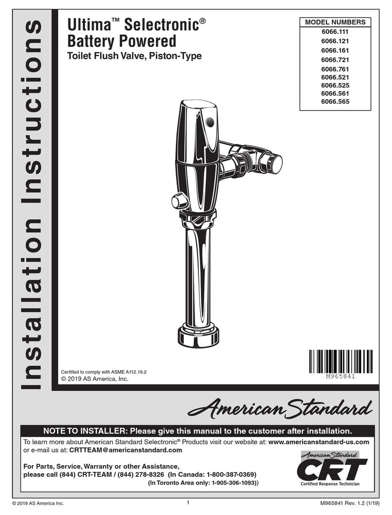
American Standard R127 User manual

American Standard

American Standard R127 User manual

American Standard SELECTRONIC 606B.111 User manual

American Standard

American Standard SELECTRONIC 606B.111 User manual

American Standard R111 User manual

American Standard

American Standard R111 User manual

American Standard Selectronic 606B.X10 User manual

American Standard

American Standard Selectronic 606B.X10 User manual

American Standard Ultima 6145SM User manual

American Standard

American Standard Ultima 6145SM User manual

American Standard 6045.101 User manual

American Standard

American Standard 6045.101 User manual

American Standard R129 User manual

American Standard

American Standard R129 User manual

American Standard Ultima 6147SM User manual

American Standard

American Standard Ultima 6147SM User manual

American Standard 7017 Series User manual

American Standard

American Standard 7017 Series User manual

American Standard BAYSPEK047A Assembly instructions

American Standard

American Standard BAYSPEK047A Assembly instructions

American Standard SELECTRONIC 6590.525 User manual

American Standard

American Standard SELECTRONIC 6590.525 User manual

American Standard SELECTRONIC 6066.111 User manual

American Standard

American Standard SELECTRONIC 6066.111 User manual

American Standard BORNEO User manual

American Standard

American Standard BORNEO User manual

American Standard 6047.8 Series User manual

American Standard

American Standard 6047.8 Series User manual

American Standard Ultima Selectronic 6064.013 User manual

American Standard

American Standard Ultima Selectronic 6064.013 User manual

American Standard ACONT401AN21MA User manual

American Standard

American Standard ACONT401AN21MA User manual

American Standard R910 Flash User manual

American Standard

American Standard R910 Flash User manual

American Standard 50A65-475 User manual

American Standard

American Standard 50A65-475 User manual

American Standard SELECTRONIC 6065.521 User manual

American Standard

American Standard SELECTRONIC 6065.521 User manual

American Standard 6047.800 User manual
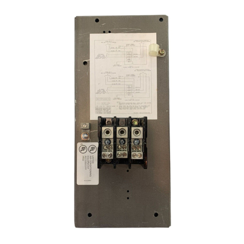
American Standard

American Standard 6047.800 User manual

American Standard AccuLink Platinum 1050 User manual
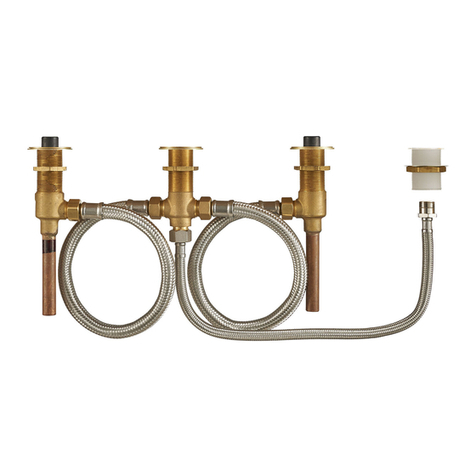
American Standard

American Standard AccuLink Platinum 1050 User manual

American Standard R110 User manual

American Standard

American Standard R110 User manual

American Standard Ultima 6045.051 User manual

American Standard

American Standard Ultima 6045.051 User manual

American Standard SELECTRONIC 6067.111 User manual

American Standard

American Standard SELECTRONIC 6067.111 User manual

Popular Control Unit manuals by other brands

GEM 660 operating instructions

GEM

GEM 660 operating instructions

Electrolux KITWSRT Use and installation  manual

Electrolux

Electrolux KITWSRT Use and installation manual

VMIC VMIVME-7455 installation guide

VMIC

VMIC VMIVME-7455 installation guide

WAGO 751-3502 manual

WAGO

WAGO 751-3502 manual

ActronAir LC7-2W installation instructions

ActronAir

ActronAir LC7-2W installation instructions

GE MM3 instruction manual

GE

GE MM3 instruction manual

Yoshitake GD-21 product manual

Yoshitake

Yoshitake GD-21 product manual

H3C PSR180-56A user manual

H3C

H3C PSR180-56A user manual

Parker CK-1 Installation, Service and Parts Information

Parker

Parker CK-1 Installation, Service and Parts Information

Sharp PN-ZB03 Series installation manual

Sharp

Sharp PN-ZB03 Series installation manual

Emerson BM6X Series instruction manual

Emerson

Emerson BM6X Series instruction manual

ATI Technologies VB12-M Installation and operation manual

ATI Technologies

ATI Technologies VB12-M Installation and operation manual

YASKAWA MP2000 Series user manual

YASKAWA

YASKAWA MP2000 Series user manual

Land Pride 380-166A installation instructions

Land Pride

Land Pride 380-166A installation instructions

Landis+Gyr WZU-M Series Installation and operating guide

Landis+Gyr

Landis+Gyr WZU-M Series Installation and operating guide

Digitrax SMBK manual

Digitrax

Digitrax SMBK manual

Argo-Hytos EL6 quick start guide

Argo-Hytos

Argo-Hytos EL6 quick start guide

KERAFLO AYLESBURY KB installation guide

KERAFLO

KERAFLO AYLESBURY KB installation guide

manuals.online logo
manuals.online logoBrands
  • About & Mission
  • Contact us
  • Privacy Policy
  • Terms and Conditions

Copyright 2025 Manuals.Online. All Rights Reserved.