Duramaxx 90010 User manual

55 lbs TROLLING MOTOR
MODEL: 90010
TM
Owner's Manual
WARNING
TOLL FREE HELPLINE: 1 866 456-8934
CAUTION
READ THIS MANUAL CAREFULLY BEFORE OPERATING YOUR DURAMAXXTM TROLLING
MOTOR. RETAIN FOR FUTURE REFERENCE.

TABLE OF CONTENTS
FEATURE INFORMATION ..................................................................................................................
BATTERY .........................................................................................................................................
4-6
7
8-9
3
ADJUSTMENT ..................................................................................................................................
OPERATION .........................................................................................................................................
10
PROPELLER REPLACEMENT ..........................................................................................................
MAINTENANCE ..................................................................................................................................
EXPLODED VIEW ..............................................................................................................................
PARTS LIST .......................................................................................................................................
SPECIFICATIONS
MODEL NO .................................................................................................................................
MOTOR ..........................................................................................................................................
90010
THRUST ......................................................................................................................................
12 V
55 lbs
PROP SPEED ......................................................................................................................2000 RPM
FORWARD SPEED .............................................................................................................5 SPEEDS
REVERSE SPEED .............................................................................................................. 3 SPEEDS
NOTE: To be used with Deep Cycle 12 V marine battery (Sold Separately).
2
SPECIFICATIONS ............................................................................................................................... 2
TROUBLESHOOTING.........................................................................................................................
LIMITED WARRANTY.........................................................................................................................13
12
11
14
15
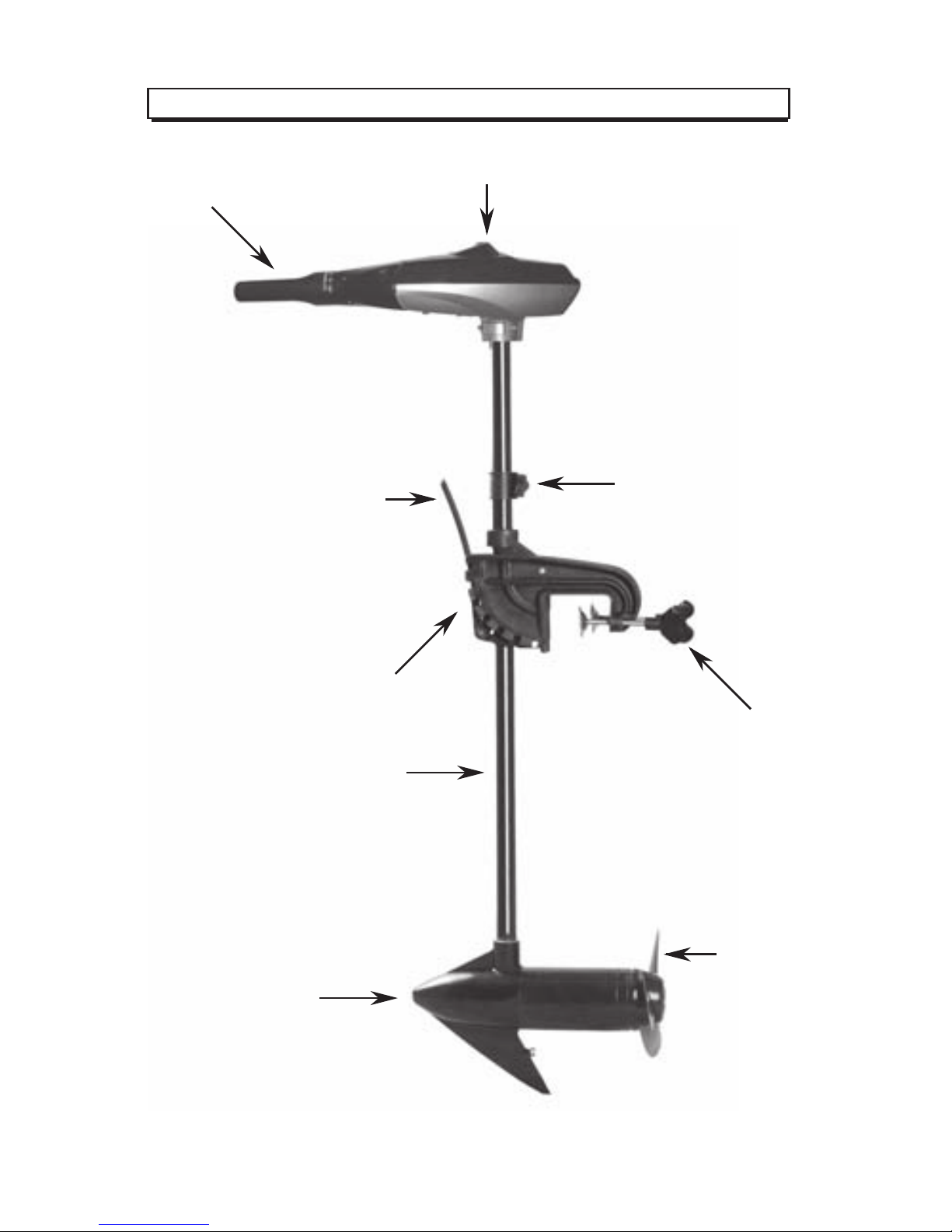
FEATURE INFORMATION
3
Tilt Twist
Tiller Handle Battery Meter
Depth Collar Knob
Adjustable shaft
Clamp Screws
Propeller
Tilt lock lever
12 V DC Motor
Boat mounting bracket
ADJUSTMENT
4
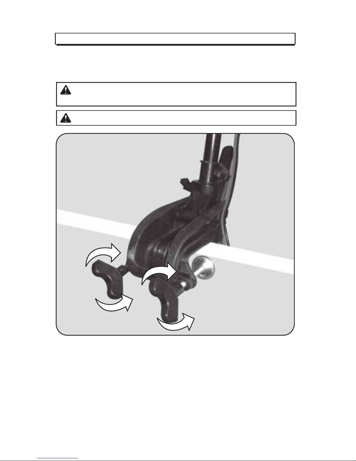
MOUNTING THE MOTOR
Install the motor on the transom of the boat. Be sure to tighten the clamp screws
securely.
WARNING:
When tilting motor, keep fingers clear of all hinge and pivot points
and all moving parts.
CAUTION:
Over-tightening the clamp screws can damage the bracket.
Tighten
Loosen

ADJUSTMENT
5
BRACKET ADJUSTMENT
You can lock your motor in a vertical position, angle it for shallow water or tilt it
completely out of the water.
• Firmly grasp the control head or steel shaft.
• Depress and hold the tilt lock lever.
• Tilt to any of the positions on the mounting bracket.
• Release the lever.

ADJUSTMENT
6
DEPTH ADJUSTMENT
• Firmly grasp the shaft and hold it steady.
• Loosen the steering tension knob and depth collar knob until the tube slides freely.
• Raise or lower the motor to the desired depth.
• Tighten depth collar knob to secure the motor in place.
STEERING ADJUSTMENT
Adjust the steering tension knob to provide enough tension to allow the motor to turn
freely, yet remain in position without being held or; Tighten the knob and lock the
motor in a preset position to leave your hands free for fishing.
IMPORTANT:
When setting the depth, be sure the top of the motor is
submerged at least 12” (30 cm) to avoid churning or agitation of surface water. The
propeller must be completely submerged.
Depth Collar Knob
Steering tension knob

OPERATION
7
TILT TWIST TILLER
These motors offer a choice of five forward and three reverse speeds. The speed
control may be operated in either direction, forward or reverse.
• Turn the tilt twist tiller handle counterclockwise from O (off) to increase reverse speed.
• Turn the tilt twist tiller handle clockwise from O (off) to increase forward speed.
Thrust decreases as you approach O from either direction. The numbers printed on the
twist grip handle represent a percentage of maximum thrust.
The twist grip tiller handle is shipped in the down position. Firmly pull the handle up to
the horizontal position. The handle has five available positions:45º down, horizontal,
15º, 30º and 45º tilted up. The handle locks in the horizontal position, but can be tilted
down by pushing the release button located on the left underside of the handle pivot.
CAUTION:
Never operate your motor when it is out of the water.
OFF
Handle controls on/off,
steering, forward/reverse
Release button
BATTERY
8
12 V BATTERY INFORMATION
The motors will operate with any deep cycle marine 12 V battery.
For best results it is recommended to use a deep cycle marine battery with a
minimum of 105 ampere hour rating. As a general on the water estimate, your 12 V
motor will draw one ampere per hour for each pound of thrust produced when the
motor is running on high. The actual ampere draw is subject to your particular
environmental conditions and operation requirements.
Always store battery at full charge when not in use. Battery life will be extended by
charging each time battery is used and every two weeks when not in use. (Use a
lamp timer and charge each day for 1 hour even if battery is not use as this will help
maintain a full battery level.)
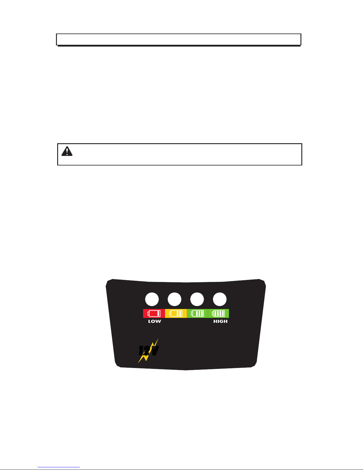
BATTERY METER
The LED provides an accurate display of the remaining charge in the battery. It is ony
accurate when the motor is off. The gauge reads as:
• Four lights indicate full charge.
• Three lights indicate good charge.
• Two lights indicate low charge.
• One light indicates recharge.
If you are using a crank battery to start a gasoline outboard it is strongly recom-
mended to use a separate battery for trolling motor to ensure of enough start up
power for the gasoline motor.
NOTE:
Only trickle charge your battery to full power, do not speed/rapid charge the
battery as this will shorten its life.
Battery Condition
1212 VV
1212 VV

BATTERY
9
BATTERY CONNECTION
12 V Systems
1. Connect the positive (+) red lead to the positive (+) battery terminal.
2. Connect the negative (-) blace lead to the negative (-) battery terminal.
NOTE:
If installing a leadwire plug, observe proper polarity and follow instructions in
your boat owner’s manual.
IMPORTANT:
This is supplied as a quick reference guide however battery types,
brands and sizes may vary in performance and abilities. Always read your battery
manufacturers manual for specific battery requirements or contact the manufacturer for
best practices and/or advice.
WARNING:
• Before connecting battery, make sure the tiller twist handle is in the off
position.
• Use only 6 gauge wire to extend power lead.
• Improper wiring of 12 V system could cause battery explosion!
• Keep leadwire wing nut connection tight and solid to the battery terminals.
• Locate battery in a ventilated compartment.

PROPELLER REPLACEMENT
10
Weedless Propeller
Drive pin
Prop nut
Washer
PROPELLER REPLACEMENT
• Hold the propeller and loosen the prop nut with a pliers or a wrench.
• Remove prop nut and washer.
NOTE: If the drive pin is sheared/broken, you will need to hold the shaft steady with a
screwdriver blade pressed into the slot on the end of the shaft.
• Turn the old prop to horizontal (as illustrated) and pull it straight off. If the drive pin
falls out, push it back in.
• Align new propeller with drive pin.
• Install prop washer and prop nut.
• Tighten prop nut 1/4 turn past snub. (25-35 inch lbs.)
IMPORTANT:
If the prop nut is overtightened it may cause damage to the prop or
cause too much pressure/strain on the motor which may cause overheating or premature
battery drain.
CAUTION:
Disconnect the motor from the battery before beginning any prop work
or maintenance.
Slot End
Table of contents


