DSX12VD Manual Copyright 2006 Mpegbox.com
Page 1 of 6
DuraWatt DS12VD
140-Watt DC-DC 12 Volt Power Supply
Short Form User Manual
Version 1.0
Table of Contents
1.
Getting Started......................................................................................................................................1
1.1.
Introduction...........................................................................................................................................1
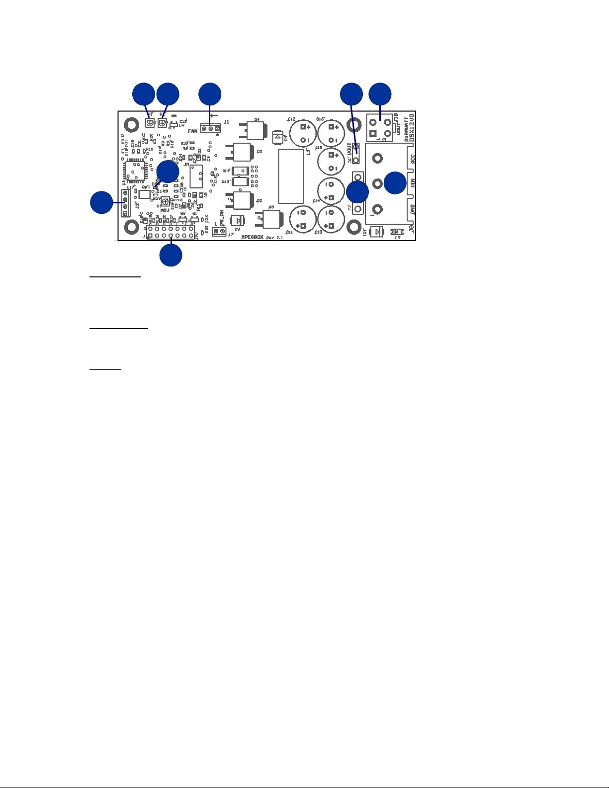
1.2.
Product Photo...............................................................................................................................2
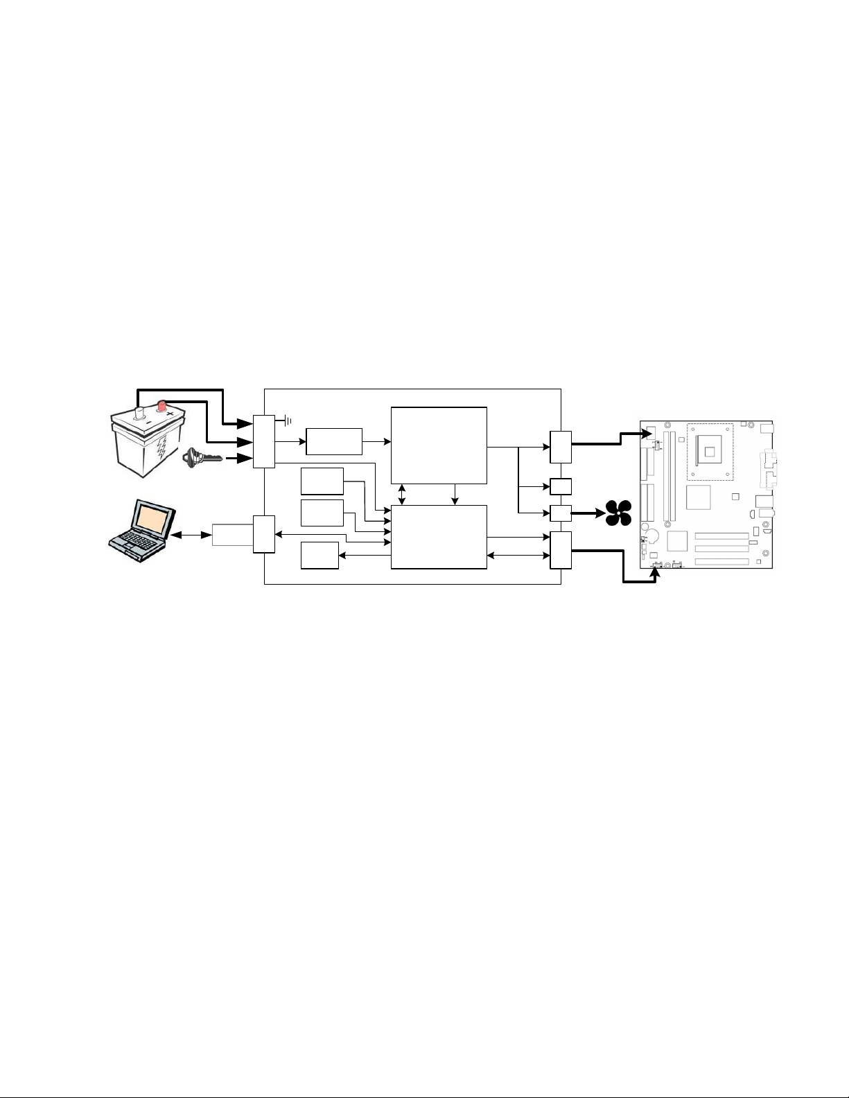
1.3.
Block Diagram...............................................................................................................................2
1.4.
Included Contents and Optional Accessories................................................................................2
1.5.
Recommended Additional Supplies ..............................................................................................3
1.6.
Recommended Tools....................................................................................................................3
1.7.
Connection Overview Diagram .....................................................................................................3
1.8.
Precautions and Warnings............................................................................................................3
1.9.
Detailed Connection Diagram.......................................................................................................4
2.
Specifications.......................................................................................................................................5
2.1.
Electrical .......................................................................................................................................5
2.2.
Mechanical....................................................................................................................................5
4.
Mpegbox.com Limited Warranty.........................................................................................................6
1. Getting Started
1.1. Introduction
Thank you for purchasing a DSX12VD Automotive 12 Volt Power Supply. Please take some time to read
through this manual before attempting to use this product.
The DSX12VD is the optimal solution for providing a stable and clean 12-volt power source to a variety of
electronic devices in an automobile. A stable 12-volts is achieved by the buck-boost topology which allows the
input to be above or below the output. The DSX12VD provides a stable 12-volts even if the input has dips,
spikes, or noise. This makes it optimal for powering 12-volt computers intended for indoor use. These
computers typically use an AC-DC converter that puts out a stable 12-volts (i.e. + - 10%). Automotive 12-volt
power systems do put out 12 volts, however the drain from motors, heaters, headlights, etc. cause the voltage
to vary outside the +- 5% or +-10% required by sensitive computing equipment. A voltage range of 8-16 volts
is not uncommon in a 12-volt automotive system which is effectively 12-volts +-50%. Subjecting electronic
devices to voltage ranges this far outside their specification can at best cause erratic behavior, and at worst
cause failure or fire.
The DSX12VD has advanced microprocessor control enabling features such as Startup/Shutdown
Sequencing, Low Voltage Battery Protection, and Temperature Protection. Features also include Serial Port
Control, Diagnostics, and Upgradeability. Desktop computer motherboards are typically not designed to work
in automotive environments, the design and engineering that went into the DSX12VD makes every attempt to
compensate for this. Having purchased a DSX12VD, you will rest assured that you’ve invested in a flexible
product that can grow and expand with your automotive computing system.