DURHAND B20-070 User manual

INcec022V02_CA
Save This Manual Keep this manual for the safety Warnings and precautions,
assembly, operating, inspection, maintenance and cleaning procedures.
Diagrams within this manual may not be drawn proportionall.
Due to continuing
improvements, actual product may differ slightly from the
product described herein.
Tools required for assembly and service may not be included.
UESR’S MANUAL
B20-070
EN

Important Safety Information
Assembly Precautions
1. Assemble only according to these instructions. Improper assembly can create
hazards.
2. Wear ANSI-approved safety goggles and heavy-duty work gloves during assem-
bly.
3. Keep assembly area clean and well lit.
4. Keep bystanders out of the area during assembly.
5. Do not assemble when tired or when under the influence of drugs or medication.
6. Weight capacity and other product capabilities apply to properly and completely
assembled product only
Use Precautions
1. This product is not a toy. Do not allow children to play with or near this item.
2. Use as intended only.
3. Inspect before every use; do not use if parts are loose or damaged.
4. Do not exceed listed weight capacity, evenly distributed and balanced. Be aware
of dynamic loading! Sudden load movement may briefly create excess load causing
product failure.
5. Maintain product packaging and nameplates. These carry important safety infor-
mation.
6. Operate and store the Cart on a flat, dry, level surface.
7. Read welding equipment manual before use.
8. If using gas cylinders, be especially careful to prevent tipping or damage to the
cylinders. Follow gas cylinder supplier’sand gas supplier’s safety instructions at all
times.
-2-

Assembly Instructions
Read the ENTIRE IMPORTANT SAFETY INFORMATION section
at the beginning of this document including all text under sub-
headings therein before set up or use of this product.
Note: When attaching hardware, hand tighten only until the unit is together, then
use the appropriate tools to tighten the hardware.
1. Put a Wheel (2) on the end of the Axle (9) and secure it with Washer and Cotter
Pin (11). See Figure A. Repeat on the other side.Figure A: Wheel Attachment
2. Using four Bolts and Nuts (10), attach a Caster (3) to the Bottom Shelf (1). See
Figure B. Repeat on other side.
3. Connect the bottom (note the hole locations in the diagram) of the Left Support
(7a) to the Bottom Shelf (1) using Bolts and Nuts (10). See Figure C. Repeat on
other side with Right Support (7b).
Figure A: Wheel Attachment Figure B: Caster Attachment
Figure C: Connection of
Bottom Shelf and Left Support
-3-

4. Attach the Middle Shelf (5) to the Left and Right Supports (7a,7b) using Bolts and
Nuts (10).
5. Place a Hook (8) over the holes on the outside of the top of a Support (7a/7b),
and place the Bolts (10) through both the Hook (8), Support (7a/7b), and the Top
Shelf (6). Secure with Nuts (10). Repeat on other side.
6. Attach the Back Panel (4) to the Bottom Shelf (1) using Bolts and Nuts (10).
7. Attach the Back Panel (4) to the Middle Shelf (5) and the Top Shelf (6) using
Bolts and Nuts (10).
8. Insert the Chains (12) through the holes in the Back Panel (4).
9. Wrench tighten all of the hardware.
1. Make sure that the welder and all accessories combined do not exceed the
weight capacity of this cart.
2. Place any gas cylinders on the back shelf, and secure in place with both chains.
Adjust chains’ length to hold the cylinder(s) securely.
3. Place the welder on the top shelf and the other accessories on the other shelves.
4. Make sure everything is secure and the cart is well balanced. If the welder is
unstable or does not fit securely on the shelf, do not use that welder with this cart.
Operation
Maintenance
1. Periodically tighten all of the hardware.
2. Make sure the casters and wheels are free of all dirt, debris, or grease.
THE MANUFACTURER AND/OR DISTRIBUTOR HAS PROVIDED THE PARTS
LIST AND ASSEMBLY DIAGRAM IN THIS DOCUMENT AS A REFERENCE TOOL
ONLY. NEITHER THE MANUFACTURER OR DISTRIBUTOR MAKES ANY REP-
RESENTATION OR WARRANTY OF ANY KIND TO THE BUYER THAT HE OR
SHE IS QUALIFIED TO MAKE ANY REPAIRS TO THE PRODUCT, OR THAT HE
OR SHE IS QUALIFIED TO REPLACE ANY PARTS OF THE PRODUCT. IN FACT,
THE MANUFACTURER AND/OR DISTRIBUTOR EXPRESSLY STATES THAT ALL
REPAIRS AND PARTS REPLACEMENTS SHOULD BE UNDERTAKEN BY CERTI-
FIED AND LICENSED TECHNICIANS, AND NOT BY THE BUYER. THE BUYER
ASSUMES ALL RISK AND LIABILITY ARISING OUT OF HIS OR HER REPAIRS
TO THE ORIGINAL PRODUCT OR REPLACEMENT PARTS THERETO, OR ARIS-
ING OUT OF HIS OR HER INSTALLATION OF REPLACEMENT PARTS THERE-
TO.
PLEASE READ THE FOLLOWING CAREFULLY
-4-

Parts List and Diagram
Part Description Qty.
1 Bottom Shelf 1
2 Wheel 6" 2
3 Swivel Caster 2
4 Vertical Support Panel 1
5 Center Shelf 1
6 Top Shelf 1
Part Description Qty.
7a Left Support 1
7b Right Support 1
8 Hook 2
9 Axle 1
10 Bolts, Washers, Nuts (set) 33
11 Flat Washers, Cotter Pin (set) 2
12 Chain 2
6
8 10
3
11
5
4
12
1
9 2
7a
8
Note: Some parts are listed and shown for illustration purposes only, and are not
available individually as replacement parts.
-5-

Conservez Ce Manuel Consultez ce manuel pour prendre connaissance
des avertissements et des mesures de sécurité, des procédures de montage, d'utili-
sation, d'inspection, d'entretien et de nettoyage.
Les diagrammes contenus dans ce manuel peuvent ne pas
être dessinés proportionnellement. En raison de l'amélioration
continue, le produit réel peut différer légèrement du produit
décrit ici. Les outils nécessaires au montage et à l'entretien
peuvent ne pas être inclus.
Lisez ce document avant d'utiliser ce produit.
Le non-respect de cette consigne peut entraîner
des blessures graves.
Conservez ce manuel.
AVERTISSEMENT
CAPACITÉ 100 LB
CHARIOT DE SOUDAGE
-6-
FR

Consignes Importantes de Sécurité
Précautions d'Assemblage
1.N'effectuez le montage que conformément à ces instructions. Un assemblage
incorrect peut provoquer des risques.
2.Portez des lunettes de sécurité homologuées ANSI et des gants de travail résis-
tants pendant le montage
3.Gardez la zone d'assemblage propre et bien éclairée.
4.Ne laissez pas les personnes tierces accéder à la zone pendant le montage.
5.Ne pas assembler lorsque vous êtes fatigué ou sous l'influence de drogues ou de
médicaments.
6.La capacité de charge et les autres capacités du produit ne sont valables que
lorsque le produit est correctement et complètement assemblé.
Précautions d'Utilisation
1.Ce produit n'est pas un jouet. Ne laissez pas les enfants jouer avec ou près de
cet article.
2.Employez-le conformément à l'usage prévu.
3.Inspecter avant chaque utilisation ; ne pas utiliser si des pièces sont desserrées
ou endommagées.
4.Ne pas dépasser la capacité de charge indiquée, répartie de manière égale et
équilibrée.
Attention à la charge dynamique ! Un mouvement soudain de la charge peut créer
brièvement une surcharge et entraîner une défaillance du produit.
5.Conservez l'emballage du produit et les plaques signalétiques. Ils contiennent
des informations importantes relatives à la sécurité.
6.Utiliser et ranger le chariot sur une surface plane, sèche et de niveau.
7.Lire le manuel de l'équipement de soudage avant de l'utiliser.
8.Si vous utilisez des bouteilles de gaz, faites particulièrement attention à ne pas
les faire basculer ou les endommager. Observez en permanence les instructions de
sécurité du fournisseur de bouteilles de gaz.
-7-

Instructions de Montage
Lisez la section CONSIGNES IMPORTANTE DE SÉCURITÉ EN-
TIEREMENT au début de ce document, y compris tout le texte
des sous-titres, avant de monter ou d'utiliser ce produit.
Remarque : Lorsque vous fixez les pièces, serrez-les à la main uniquement
jusqu'à ce que l'unité soit complètement assemblée, puis à l'aide des outils appro-
priés, serrez les pièces.
1. Put a Wheel (2) on the end of the Axle (9) and secure it with Washer and Cotter
Pin (11). See Figure A. Repeat on the other side.Figure A: Wheel Attachment
2. Using four Bolts and Nuts (10), attach a Caster (3) to the Bottom Shelf (1). See
Figure B. Repeat on other side.
3.Reliez le bas (notez l'emplacement des trous dans le schéma) du Support
Gauche (7a) à la Tablette Inférieure (1) à l'aide des Boulons et Écrous (10).
Voir la figure C. Répéter de l'autre côté avec le Support Droit (7b).
Figure A: Fixation des Roues Figure B: Fixation des roulettes
Figure C: Connexion de la Tablette
Inférieure au Support Gauche
-8-

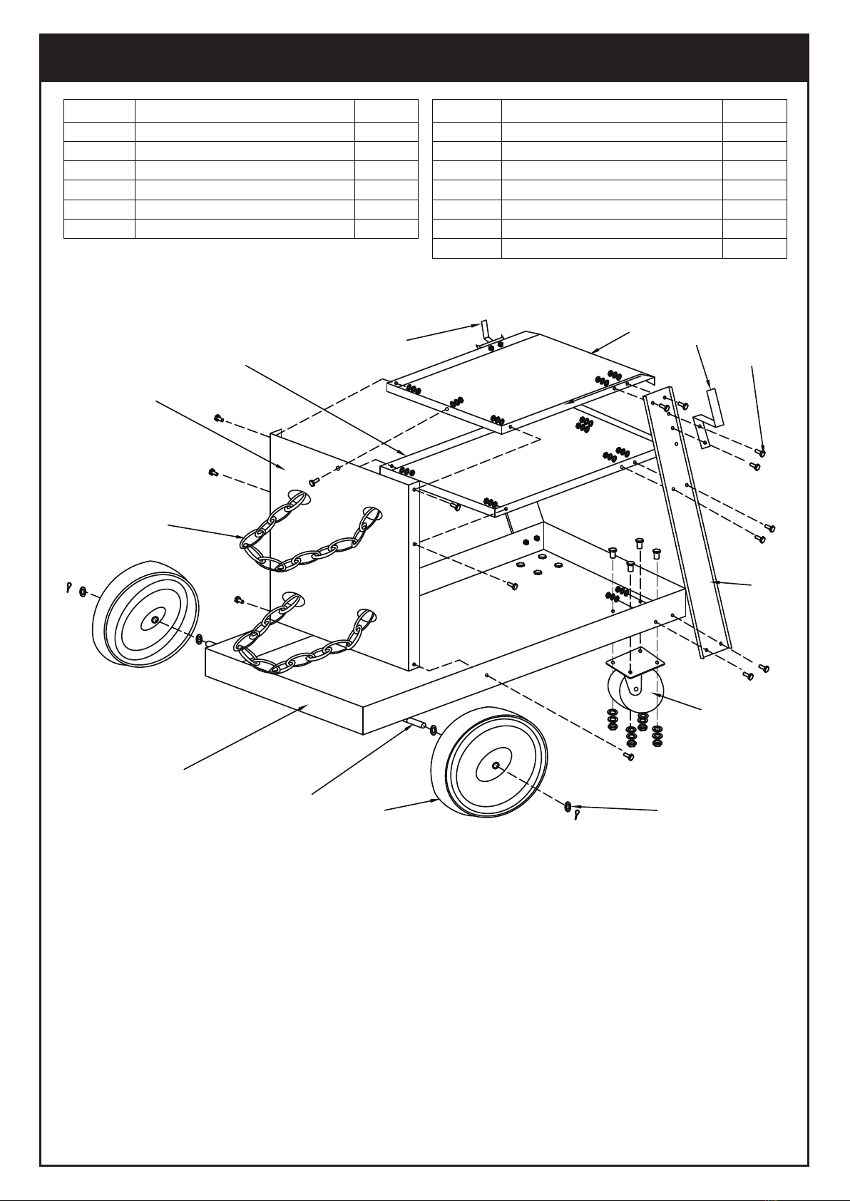
4.Fixez la Tablette Centrale (5) aux Supports Gauche et Droit (7a,7b) à l'aide des Boulons
et Ecrous (10).
5.Placer un Crochet (8) sur les trous situés à l'extérieur du haut d'un Support (7a/7b), et
placer les Boulons (10) à travers le Crochet (8), le Support (7a/7b), et la Tablette
supérieure (6). Fixer avec les écrous (10). Répéter l'opération de l'autre côté.
6.Fixer le Panneau Arrière (4) à la Tablette Inférieure (1) en utilisant les Boulons et Ecrous
(10).
7.Fixer le Panneau Arrière (4) à la Tablette Centrale (5) et à la Tablette Supérieure (6) à
l'aide des Boulons et Ecrous (10).
8.Insérer les Chaînes (12) dans les trous du Panneau Arrière (4).
9.Serrez à la clé toute la quincaillerie.
1.Assurez-vous que le poste de soudure et tous les accessoires combinés ne dépassent
pas la capacité de charge du chariot.
2.Placez les bouteilles de gaz sur la tablette arrière et fixez-les en place avec les deux
chaînes. Ajustez la longueur des chaînes pour maintenir la ou les bouteilles en place.
3.Placez le poste de soudure sur l'étagère supérieure et les autres accessoires sur les
autres étagères.
4.Si le poste de soudure est instable ou ne tient pas bien sur l'étagère, n'utilisez pas ce
poste avec ce chariot.
Operation
Maintenance
1. Serrez périodiquement toutes les pièces.
2. Assurez-vous que les roulettes et les roues sont exemptes de toute saleté, débris ou
graisse.
LA LISTE DES PIÈCES ET LE SCHÉMA DE MONTAGE DU PRÉSENT DOCUMENT
SONT FOURNIS PAR LE FABRICANT ET LE DISTRIBUTEUR À TITRE D'OUTIL DE
RÉFÉRENCE UNIQUEMENT.
NI LE FABRICANT NI LE DISTRIBUTEUR NE FONT DE DÉCLARATION OU NE DON-
NENT DE GARANTIE DE QUELQUE NATURE QUE CE SOIT À L'ACHETEUR QU'IL OU
ELLE EST QUALIFIÉ(E) POUR EFFECTUER DES RÉPARATIONS SUR LE PRODUIT.
QU'IL OU ELLE EST QUALIFIÉ(E) POUR REMPLACER TOUTE PIÈCE DU PRODUIT.
EN FAIT, LE FABRICANT ET/OU LE DISTRIBUTEUR DÉCLARE EXPRESSÉMENT QUE
TOUTES LES RÉPARATIONS ET TOUS LES REMPLACEMENTS DE PIÈCES DOIVENT
ÊTRE EFFECTUÉS PAR DES TECHNICIENS CERTIFIÉS ET AGRÉÉS, ET NON PAR
L'ACHETEUR. L'ACHETEUR ASSUME TOUS LES RISQUES ET TOUTES LES RE-
SPONSABILITÉS DÉCOULANT DE SES INTERVENTIONS SUR LE PRODUIT
LUI-MÊME OU SUR LES PIÈCES DE RECHANGE DE CELUI-CI,
OU DE L'INSTALLATION DE PIÈCES DE RECHANGE SUR LE PRODUIT.
VEUILLEZ LIRE ATTENTIVEMENT CE QUI SUIT
-9-

Liste des Pièces et Schéma
6
8 10
3
11
5
4
12
1
9 2
7a
8
Remarque : Certaines pièces sont listées et représentées à des fins d'illustration
uniquement, et ne sont pas disponibles individuellement comme pièces de
rechange.
Pièce
Description
Qté.
1
Tablette inférieure
1
2
Roue de 6 pouces
2
3
Roue pivotante
2
4
Panneau de support vertical
1
5
Tablette centrale
1
6
Tablette supérieure
1
Pièce
Description
Qté.
7a
Support Gauche
1
7b
Support Droit
1
8
Crochet
2
9
Essieu
1
10
Boulons, rondelles, écrous (jeu)
33
11
Rondelles plates, goupille fendue (jeu)
2
12
Chaîne
2
-10-
Table of contents
Languages:
Popular Outdoor Cart manuals by other brands

Granite
Granite OVERLAND MEGA HERC owner's manual

Hupfer
Hupfer TTW/V operating instructions

Naterial
Naterial TROLLEY VENTURA 100X50 Assembly, Use, Maintenance Manual

Ziegler & Brown
Ziegler & Brown ZG3GCARTC Assembly instructions

TiCad
TiCad PRO quick start guide

Wenger
Wenger Tourmaster Storage Cart owner's manual