Durr Dental VistaScan Mini View User manual

EN
1611V004
2142100002L02
Installation and Operating Instructions
VistaScan Mini View


2142100002L02 1611V004 1
6.1 Installation/setup room . . . . . . . . . . 16
6.2 System requirements. . . . . . . . . . . . 16
6.3 Monitor . . . . . . . . . . . . . . . . . . . . . . 16
7 Installation . . . . . . . . . . . . . . . . . . . . . . 16
7.1 Carrying the unit . . . . . . . . . . . . . . . 16
7.2 Setting up the unit . . . . . . . . . . . . . . 16
7.3 Removing the protective film from
the touch screen . . . . . . . . . . . . . . . 17
7.4 Attaching the stylus . . . . . . . . . . . . . 17
7.5 Checking the memory card . . . . . . . 17
7.6 Electrical connections . . . . . . . . . . . 17
7.7 Connecting the unit to the network . 18
8 Commissioning and first start-up. . . . . 19
8.1 Installing and configuring the unit. . . 19
8.2 X-ray unit settings . . . . . . . . . . . . . . 22
8.3 Acceptance tests . . . . . . . . . . . . . . 23
Operation
9 Operating the touch screen . . . . . . . . . 24
9.1 Navigating . . . . . . . . . . . . . . . . . . . . 24
9.2 Using menus . . . . . . . . . . . . . . . . . . 24
9.3 Entering text in the field . . . . . . . . . . 24
9.4 Calling up messages on the touch
screen. . . . . . . . . . . . . . . . . . . . . . . 25
10 Correct use of image plates . . . . . . . . . 25
11 Operation . . . . . . . . . . . . . . . . . . . . . . . 26
11.1 X-ray . . . . . . . . . . . . . . . . . . . . . . . . 26
11.2 Scanning the image data via a
computer . . . . . . . . . . . . . . . . . . . . 28
11.3 Scanning image data via the touch
screen on the unit . . . . . . . . . . . . . . 29
11.4 Erasing the image plate . . . . . . . . . . 31
11.5 Switch off the unit.. . . . . . . . . . . . . . 31
12 Cleaning and disinfection. . . . . . . . . . . 32
12.1 Image plate scanner . . . . . . . . . . . . 32
12.2 Light protection cover . . . . . . . . . . . 33
12.3 Image plate . . . . . . . . . . . . . . . . . . . 33
12.4 Stylus . . . . . . . . . . . . . . . . . . . . . . . 34
13 Maintenance. . . . . . . . . . . . . . . . . . . . . 35
13.1 Recommended maintenance
schedule . . . . . . . . . . . . . . . . . . . . . 35
EN
Contents
Important information
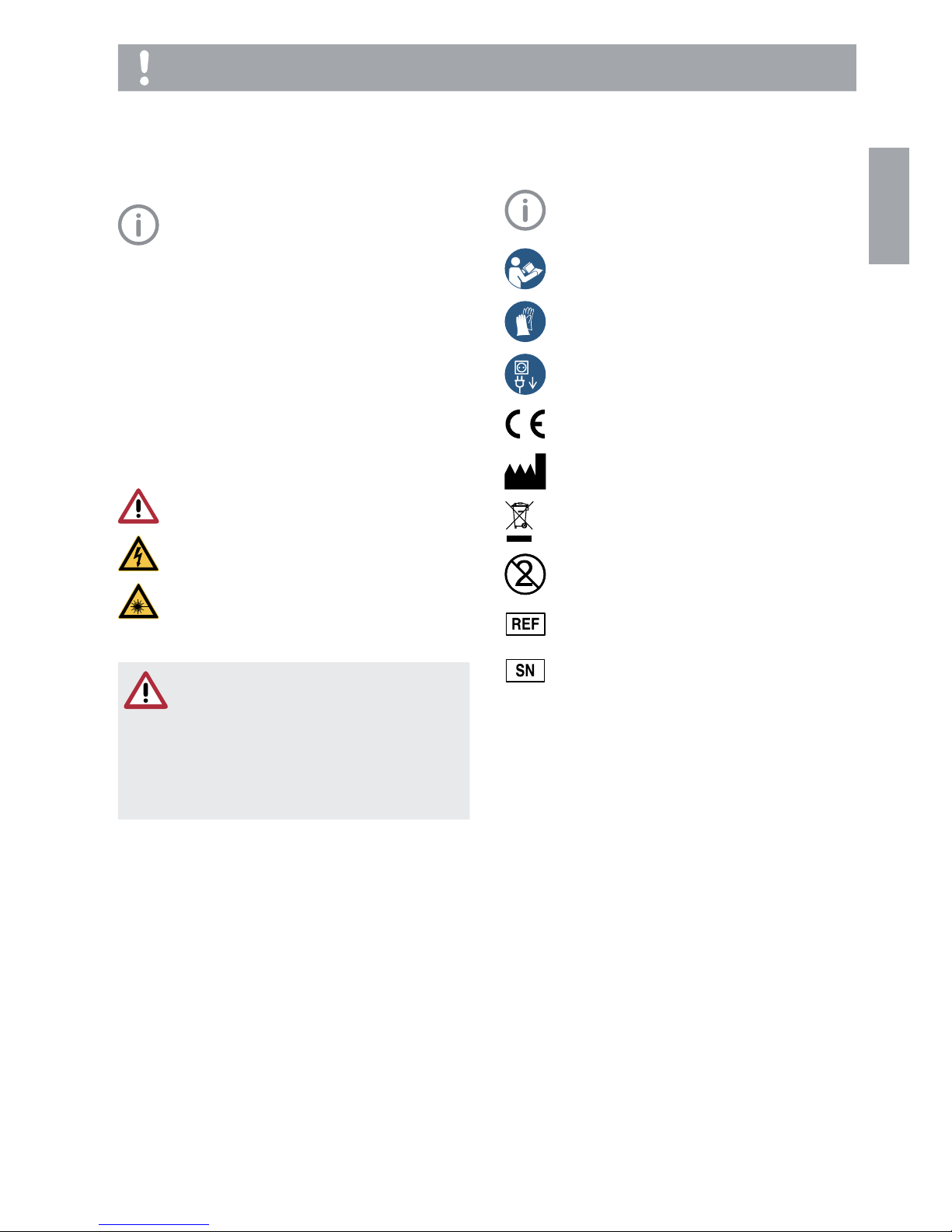
1 About this document . . . . . . . . . . . . . . . 3
1.1 Warnings and symbols . . . . . . . . . . . 3
1.2 Copyright information . . . . . . . . . . . . 3
2 Safety . . . . . . . . . . . . . . . . . . . . . . . . . . . 4
2.1 Intended purpose . . . . . . . . . . . . . . . 4
2.2 Intended use . . . . . . . . . . . . . . . . . . . 4
2.3 Improper usage . . . . . . . . . . . . . . . . . 4
2.4 General safety information . . . . . . . . . 4
2.5 Qualified personnel . . . . . . . . . . . . . . 4
2.6 Protection from electric shock . . . . . . 4
2.7 Only use genuine parts . . . . . . . . . . . 5
2.8 Transport. . . . . . . . . . . . . . . . . . . . . . 5
2.9 Disposal . . . . . . . . . . . . . . . . . . . . . . 5
Product description
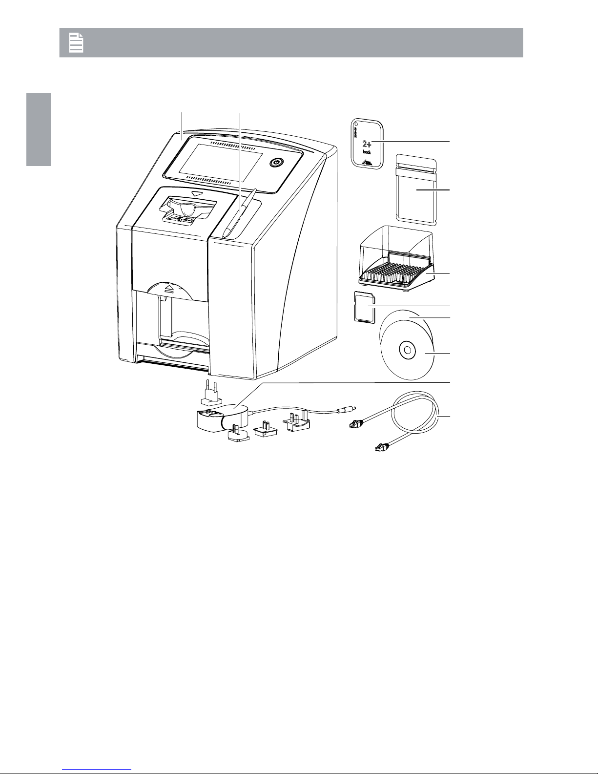
3 Overview. . . . . . . . . . . . . . . . . . . . . . . . . 6
3.1 Scope of delivery. . . . . . . . . . . . . . . . 7
3.2 Accessories. . . . . . . . . . . . . . . . . . . . 7
3.3 Special accessories. . . . . . . . . . . . . . 7
3.4 Disposable materials . . . . . . . . . . . . . 7
3.5 Wear parts and spare parts . . . . . . . . 8
4 Technical data . . . . . . . . . . . . . . . . . . . . 9
4.1 Image plate scanner . . . . . . . . . . . . . 9
4.2 Image plate . . . . . . . . . . . . . . . . . . . 10
4.3 Light protection cover . . . . . . . . . . . 11
4.4 Type plate . . . . . . . . . . . . . . . . . . . . 12
4.5 Conformity assessment . . . . . . . . . . 12
5 Operation . . . . . . . . . . . . . . . . . . . . . . . 12
5.1 Image plate scanner . . . . . . . . . . . . 12
5.2 Image plate . . . . . . . . . . . . . . . . . . . 13
5.3 Light protection cover . . . . . . . . . . . 14
5.4 Stylus . . . . . . . . . . . . . . . . . . . . . . . 14
5.5 Protective cover . . . . . . . . . . . . . . . 14
5.6 Storage box . . . . . . . . . . . . . . . . . . 14
5.7 Bite protector (optional) . . . . . . . . . . 15
Installation
6 Requirements . . . . . . . . . . . . . . . . . . . . 16

2 2142100002L02 1611V004
Contents
Troubleshooting
14 Tips for operators and service techni-
cians. . . . . . . . . . . . . . . . . . . . . . . . . . . 36
14.1 Poor X-ray image. . . . . . . . . . . . . . . 36
14.2 Software error . . . . . . . . . . . . . . . . . 40
14.3 Fault on the unit . . . . . . . . . . . . . . . 41
14.4 Error messages on the touch
screen. . . . . . . . . . . . . . . . . . . . . . . 42
Appendix
15 Settings menu layout . . . . . . . . . . . . . . 45
16 Scanning times. . . . . . . . . . . . . . . . . . . 47
17 File sizes (uncompressed) . . . . . . . . . . 48
18 Information about EMC in accord-
ance with EN 60601-1-2 . . . . . . . . . . . . 49
18.1 General information . . . . . . . . . . . . . 49
18.2 Abbreviations . . . . . . . . . . . . . . . . . 49
18.3 Guidelines and manufacturer's in-
formation. . . . . . . . . . . . . . . . . . . . . 49
EN

2142100002L02 1611V004 3
Other symbols
These symbols are used in the document and
on or in the unit:
Note, e.g. specific instructions regarding
efficient and cost-effective use of the unit.
Comply with the specification in the ac-
companying documents.
Wear hand protection.
Switch off and de-energise the device
(e.g. unplug from mains).
CE labelling
Manufacturer
Dispose of correctly in accordance with
EU Directive 2012/19/EU (WEEE).
Do not reuse
Order number
Serial number
1.2 Copyright information
All names of circuits, processes, names, soft-
ware programs and units used in this document
are protected by copyright.
The Installation and Operating Instructions must
not be copied or reprinted, neither in full nor in
part, without written authorisation from Dürr
Dental.
1 About this document
These installation and operating instructions
form part of the unit.
If the instructions and information in
these installation and operating instruc-
tions are not followed, Dürr Dental will
not be able to offer any warranty or as-
sume any liability for the safe operation
and the safe functioning of the unit.
1.1 Warnings and symbols
Warnings
The warnings in this document are intended to
draw your attention to possible injury to persons
or damage to machinery.
The following warning symbols are used:
General warning symbol
Warning – dangerous high voltage
Warning - laser beam
The warnings are structured as follows:
SIGNAL WORD
Description of the type and source of
danger
Here you will find the possible conse-
quences of ignoring the warning
iFollow these measures to avoid the
danger.
The signal word differentiates between four
levels of danger:
– DANGER
Immediate danger of severe injury or death
– WARNING
Possible danger of severe injury or death
– CAUTION
Risk of minor injuries
– NOTICE
Risk of extensive material/property damage
Important information
EN

4 2142100002L02 1611V004
Important information
This unit is not suitable for monitoring patients
over longer periods of time.
This unit must not be used in operating theatres
or similar rooms, in which dangers may arise
from the combustion of flammable materials.
The touch screen only shows a preview, which
provides an initial impression of the X-ray image.
For purposes of diagnosis the X-ray image must
be viewed on a diagnostic monitor. The preview
of the X-ray image on the touch screen is not
suitable for the purposes of diagnosis.
2.4 General safety information
iWhen operating this device always observe all
guidelines, laws, and other rules and regula-
tions that are applicable at the site of opera-
tion.
iPrior to each use, check condition of the de-
vice and make sure it is in perfect working or-
der.
iDo not convert or modify the units.
iObserve the Installation and Operating In-
structions.
iMake the Installation and Operating Instruc-
tions available to the person operating the de-
vice at all times.
2.5 Qualified personnel
Operation
Persons who operate the units must ensure safe
and correct handling based on their training and
knowledge.
iInstruct or have every user instructed in han-
dling the unit.
Installation and repairs
iInstallation, readjustments, alterations, up-
grades and repairs must be carried out by
Dürr Dental or by qualified personnel specifi-
cally approved and authorized by Dürr Dental.
2.6 Protection from electric shock
iWhen working on the units observe all the rel-
evant electrical safety regulations.
iNever touch the patient and unshielded plug
connections on the device at the same time.
iImmediately replace any damaged lines and
connections.
2 Safety
Dürr Dental has designed and constructed this
device so that when used properly and for the
intended purpose there is no danger to people
or property. Nevertheless, residual risks can re-
main. You should therefore observe the follow-
ing notes.
2.1 Intended purpose
VistaScan Mini View
The unit is intended exclusively for use in dental
applications for the scanning and processing of
image data on an image plate.
Light protection cover
The light protection cover protects the image
plate against light.
Bite protector
The bite protector protects the image plate
against mechanical damage.
2.2 Intended use
VistaScan Mini
The unit may only be operated using accesso-
ries and optional accessories specifically ap-
proved by Dürr Dental.
The unit may only be cleaned using the disin-
fectants and cleaning agents specified or ap-
proved by Dürr Dental.
Light protection cover
The light protection cover is a disposable item.
The light protection cover is designed exclusive-
ly for use with Dürr Dental image plate scanners
and Dürr Dental image plates in dental applica-
tions.
Bite protector
The bite protector is a disposable item.
The bite protector is intended solely for use with
DürrDental image plates and DürrDental light
protection covers in dental applications.
2.3 Improper usage
Any other usage or usage beyond this scope is
deemed to be improper. The manufacturer ac-
cepts no liability for damages resulting from im-
proper usage. In these cases the user/operator
will bear the sole risk.
EN

2142100002L02 1611V004 5
Important information
Image plate
The image plate contains barium compounds.
iDispose of the image plate properly in accord-
ance with the locally applicable regulations.
iIn Europe, dispose of the image plate in ac-
cordance with waste code 090199 "Wastes
not otherwise specified". Disposal as domes-
tic waste is possible.
Observe the EMC rules concerning medical
devices
iObserve specific precautionary measures re-
lating to electromagnetic compatibility (EMC)
for medical devices, see "18 Information
about EMC in accordance with EN 60601-1-
2".
2.7 Only use genuine parts
iOnly use Dürr Dental parts or accessories and
special accessories specifically approved by
Dürr Dental.
iOnly use only genuine working parts and
spare parts.
DÜRR MEDICAL accepts no liability for
damages or injury resulting from the use
of non-approved accessories or special
accessories, or from the use of non-gen-
uine working parts or spare parts.
The use of non-approved accessories,
special accessories or non-genuine
working parts / spare parts (e.g.mains
cable) can have a negative effect in terms
of electrical safety and EMC.
2.8 Transport
The original packaging provides optimum pro-
tection for the device during transport.
If required, original packaging for the unit can be
ordered from Dürr Dental.
Dürr Dental does not accept any respon-
sibility or liability for damage occurring
during transport due to the use of incor-
rect packaging, even where the unit is
still under guarantee.
iOnly transport the device in its original pack-
aging.
iKeep the packing materials out of the reach of
children.
iDo not expose the unit to any strong vibra-
tions or shocks.
2.9 Disposal
Unit
The unit must be properly disposed of.
Within the European Union, the unit must
be disposed of in accordance with EU
Directive 2012/19/EU (WEEE).
iIf you have any questions about the correct
disposal of parts, please contact your dental
trade supplier.
EN

6 2142100002L02 1611V004
3 Overview
1
3
4
5
9
2
6
7
10
8
1 VistaScan Mini View image plate scanner
2 Stylus
3 Image plate intraoral
4 Light protection cover intraoral
5 Storage box
6 SDHC memory card (fitted in the unit)
7 DBSWIN imaging software DVD
8 VistaSoft imaging software DVD
9 Power supply unit with country-specific adapter
10 Network cable
Product description
EN

2142100002L02 1611V004 7
Product description
Plus image plate, size 3
2.7 x 5.4 cm (2 pcs.) . . . . . . . . . . . 2130-043-50
Plus image plate, size 4
5.7 x 7.6 cm (1 pc.). . . . . . . . . . . . 2130-044-50
Plus ID image plate, size 0
2 x 3 cm (2 pcs.). . . . . . . . . . . . . . 2130-040-60
Plus ID image plate, size 2
3 x 4 cm (4 pcs.). . . . . . . . . . . . . . 2130-042-60
Light protection covers
Light Protection Cover Plus size 0
2 x 3 cm (100 pcs.). . . . . . . . . . . . 2130-080-00
Light Protection Cover Plus size 1
2 x 4 cm (100 pcs.). . . . . . . . . . . . 2130-081-00
Light Protection Cover Plus size 2
3 x 4 cm (300 pcs.). . . . . . . . . . . . 2130-082-00
Light Protection Cover Plus size 2
3 x 4 cm (1000 pcs.) . . . . . . . . . . . 2130-082-55
Light Protection Cover Plus size 3
2.7 x 5.4 cm (100 pcs.) . . . . . . . . . 2130-083-00
Light Protection Cover Plus size 4
5.7 x 7.6 cm (100 pcs.) . . . . . . . . . 2130-084-00
Light Protection Cover Plus size 0,
white
2 x 3 cm (100 pcs.). . . . . . . . . . . . 2130-080-50
Light Protection Cover Plus size 2,
white
3 x 4 cm (300 pcs.). . . . . . . . . . . . 2130-082-50
3.3 Special accessories
The following optional items can be used with
the device:
Wall bracket . . . . . . . . . . . . . . . . . 2141-001-00
Storage box . . . . . . . . . . . . . . . . . 2141-002-00
Bite protector, size 4 (100 pcs) . . . 2130-074-03
Image plate and film holder system set
2130-981-50
Image plate and film holder system
conversion set for endo-exposures 2130-981-51
Copper dot set, self-adhesive . . . . 2130-006-00
Mobile Connect (for using apps for
mobile appliances, e.g.Dürr Dental
Imaging iPad app) . . . . . . . . . . .2100-725-12FC
Commissioning and intraoral constancy tests
Intra / Extra Digital test body . . . . . 2121-060-54
3.1 Scope of delivery
The following items are included in the scope of
delivery (possible variations due to country-spe-
cific requirements and/or import regulations):
VistaScan Mini View
image plate scanner . . . . . . . . . . . . . 2142-01
VistaScan Mini View
image plate scanner . . . . . . . . . . . . . 2142-05
VistaScan Mini View
image plate scanner . . . . . . . . . . . . . 2142-07
VistaScan Mini View
image plate scanner . . . . . . . . . . . . . 2142-08
VistaScan Mini View
image plate scanner . . . . . . . . . . . . . 2142-71
– VistaScan Mini View basic unit
– Power supply unit
– Network cable
– SDHC memory card
– Stylus
– VistaSoft imaging software DVD
– DBSWIN imaging software DVD
– Image plates:
- Size 0
- Size 2
– Light protection covers Plus:
- Size 0
- Size 2
– Storage box
– Protective cover
– Image plate cleaning wipes
– Installation and operating instructions
– Quick start instructions
3.2 Accessories
The following articles are necessary for the op-
eration of the unit, depending on the applica-
tion:
SDHC memory card . . . . . . . . . . . 9000-134-18
Image plates
Plus image plate, size 0
2 x 3 cm (2 pcs.). . . . . . . . . . . . . . 2130-040-50
Plus image plate, size 1
2 x 4 cm (2 pcs.). . . . . . . . . . . . . . 2130-041-50
Plus image plate, size 2
3 x 4 cm (4 pcs.). . . . . . . . . . . . . . 2130-042-50
Plus image plate, size 2
3 x 4 cm (12 pcs.). . . . . . . . . . . . . 2130-042-55
EN

8 2142100002L02 1611V004
Product description
3.4 Disposable materials
The following materials are consumed during
operation of the device and must be reordered
separately:
Cleaning and disinfection
Image plate cleaning wipe
(10pcs.) . . . . . . . . . . . . . . . . . . CCB351B1001
FD 350 Classic disinfection
wipes . . . . . . . . . . . . . . . . . . . . CDF35CA0140
FD 333 rapid surface disinfectant . CDF333C6150
FD 322 rapid surface disinfectant . CDF322C6150
FD 366 quick-acting disinfectant
for sensitive surfaces. . . . . . . . . CDF366C6150
Light protection covers
see "3.2 Accessories"
3.5 Wear parts and spare parts
Image plates
see "3.2 Accessories"
Information on spare parts can be found
on the website portal for authorised spe-
cialist dealers under:
www.duerrdental.net.
EN

2142100002L02 1611V004 9
Product description
4 Technical data
4.1 Image plate scanner
Electrical data for the unit
Voltage V DC 24
Max. current consumption A 1.25
Output W < 30
Type of protection IP20
Electrical data for the power supply unit
Voltage V AC 100 - 240
Frequency Hz 50 - 60
Protection class II
Type of protection IP20
Over-voltage category II
Output W < 40
Max. current consumption A 0.8
Classification
Medical Devices Directive (93/42/EEC) Class I
Laser class (unit)
in accordance with EN60825-1 1
Laser source
Laser class
in accordance with EN60825-1 3B
Wavelength lnm 635
Output mW 10
Noise level
Ready to scan dB(A) approx. 37
During scanning dB(A) approx. 55
General technical data
Dimensions (W x H x D) mm 226 x 275 x 243
Weight kg Approx. 7
Heat output W < 40
Duty cycle S2 (in accordance with VDE
0530-1) min. 25
Duty cycle S6 (in accordance with VDE
0530-1) % 25
Pixel size (selectable) μm 12.5 - 50
Max. resolution (depending on image
plate)
Line pairs/
mm (Lp/mm) Approx. 40
Network connection
LAN technology Ethernet
Default IEEE 802.3u
Data rate Mbit/s 100
EN

10 2142100002L02 1611V004
Product description
Network connection
Connector RJ45
Type of connection Auto MDI-X
Cable type ≥CAT5
WLAN connection
WLAN technology 802.11b/g
Encryption WPA, WPA2
Memory card
Type SDHC
Maximum memory capacity GB 32
File system FAT32
Performance class Class ≥4
Ambient conditions during operation
Temperature °C +10 to +35
Relative humidity % 20 - 80
Air pressure hPa 750 - 1060
Height above sea level m < 2000
Ambient conditions during storage and transport
Temperature °C -20 to +60
Relative humidity % 10 - 95
Air pressure hPa 750 - 1060
Height above sea level m < 16000
4.2 Image plate
Classification
Medical Devices Directive (93/42/EU) Class IIa
Ambient conditions during operation
Temperature °C 18 - 45
Relative humidity % < 80
Ambient conditions during storage and transport
Temperature °C < 33
Relative humidity % < 80
Dimensions of intraoral image plates
Size 0 mm 22 x 35
Size 1 mm 24 x 40
Size 2 mm 31 x 41
Size 3 mm 27 x 54
Size 4 mm 57 x 76
EN

2142100002L02 1611V004 11
Product description
4.3 Light protection cover
Classification
Medical Devices Directive (93/42/EU) Class I
EN

12 2142100002L02 1611V004
Product description
5 Operation
5.1 Image plate scanner
1
2
3
5
4
6
1 Operating elements
2 Input unit
3 Stylus
4 Release key
5 Collection tray
6 Memory card slot
The image plate scanner is used to read image
data stored on the image plate.
The unit can be used in two different ways: via
the imaging software (e.g. VistaSoft) on a PC or
directly via the touch screen on the unit.
The transport mechanism guides the image
plate through the unit. The image plate is read
using a laser inside the scanner unit. The
scanned data is converted into a digital image.
If a scanning job is started via the imaging soft-
ware, the image is automatically transmitted to
the computer.
If a scanning job is started via the touch screen,
the image is saved to the memory card and
then needs to be transferred to the computer.
4.4 Type plate
The type plate is located on the rear of the unit.
REF Order number
SN Serial number
4.5 Conformity assessment
This device has been subjected to conformity
acceptance testing in accordance with the cur-
rent relevant European Union guidelines. This
equipment conforms to all relevant require-
ments.
EN

2142100002L02 1611V004 13
Product description
unit manages the X-ray jobs in a waiting list from
which the required X-ray job can be selected
using the touch screen and then executed.
Without ScanManager the unit processes one
image at a time and is blocked until this job has
been completed. During this time no further X-
ray jobs can be transmitted to the unit from oth-
er computers.
ScanManager can be enabled via Set-
tings > System Settings> Operating
Mode.
5.2 Image plate
The image plate stores X-ray energy, which is
re-emitted in the form of light after excitation via
the laser. This light is then converted to image
information in the image plate scanner.
The image plate has an active side and an inac-
tive side. The image plate must always be ex-
posed on the active side.
When used properly, image plates can be ex-
posed, read and erased several hundred times
provided there is no mechanical damage. The
image plate must be replaced if there are any
signs of damage, e.g. if the protective layer is
damaged or there are visible scratches that
could interfere with the diagnosis.
Intraoral
2
1
1 Inactive side Black, printed with the
word "back" and the size
and manufacturer's infor-
mation
2 Active side Light blue, with position-
ing aid
The positioning aid is visible on the X-ray im-
age and makes it easier to align the image cor-
rectly during diagnosis.
Exposure from the wrong side
A marker is attached to the inactive side of the
image plate.
After scanning, the image plate runs through the
erasure unit. Image data still held on the image
plate is erased with the aid of bright light.
The image plate is then ejected for re-use.
Operating elements
1
2
1 Touch screen
2 On/off switch
The touch screen allows the unit to be operated
when it is not connected to a computer. Instruc-
tions can be entered on the touch screen either
with the tip of a finger or the stylus.
The Help button can be used to open a help
page for the relevant screen. The Messages
button can be used to call up current messag-
es.
Connections
The connections are located on the rear of the
unit, underneath the cover.
1
2
3
4
5
1 Connection for power supply unit
2 Reset button
3 AUX connection for diagnostic units
4 Network connection status LEDs
5 Network connection
ScanManager
When the ScanManager is enabled, more than
one X-ray job can be transmitted to the unit
from different computers simultaneously. The
EN

14 2142100002L02 1611V004
Product description
5.3 Light protection cover
The light protection cover provides several pro-
tective functions for the intraoral image plate:
– Protection against sunlight and UV light, and
therefore protection against accidental erasure
– Protection against mechanical damage
– Protection against contamination and soiling
The light protection cover is a disposable item.
5.4 Stylus
The touch screen can be operated using the
stylus as an alternative to the tip of a finger.
5.5 Protective cover
The protective cover protects the device against
dust and dirt, for example during extended peri-
ods inwhich it is not in use.
5.6 Storage box
Image plates packaged in light protection cov-
ers can be stored in the storage box until they
are next used. The storage box protects the im-
age plate and the light protection cover against
contamination and dirt.
1
1 Marker
If the image plate has been exposed from the
wrong side, the marker is visible as a shadow in
the X-ray image.
1
1 Marker visible as a shadow
The image can be corrected by mirroring it in
the software. If a diagnosis is not possible in the
area of the marker then the image will need to
be acquired again.
With the aid of the copper dots set you
can retrospectively add a marker to im-
age plates (see "3.3 Special accesso-
ries").
Clear assignment of image plate to image (Im-
age Plate Plus ID only)
On the Image Plate Plus ID there is also a hexa-
decimal code on the image plate in addition to
the marker. This code can be seen in the X-ray
image.
This code allows you to clearly assign the cor-
rect image plate to the X-ray image.
1
1 Hexadecimal code
EN

2142100002L02 1611V004 15
Product description
5.7 Bite protector (optional)
The bite protector protects the image plate
size4 as well as the light protection cover
against heavy mechanical damage, e.g. if the
patientbites down too hard during the X-ray ex-
posure.
EN

16 2142100002L02 1611V004
7 Installation
7.1 Carrying the unit
NOTICE
Risk of damage to sensitive compo-
nents in the unit as a result of shocks
or vibrations
iDo not expose the unit to any strong
vibrations or shocks.
iDo not move the unit during opera-
tion.
7.2 Setting up the unit
Portable and mobile HF communication appli-
ances can interfere with the effectiveness of
electrical medical devices.
iDo not stack the unit next to or together with
other appliances.
iIf, however, this unit is operated next to other
units or stacked with other units, monitor the
unit carefully in the configuration selected in
order to ensure normal operation.
The unit can be set up as a tabletop unit or
mounted on a wall using the wall bracket.
The load-bearing capacity of the table or wall
must be suitable for the weight of the unit (see
"4 Technical data").
Setting the unit on a table
To prevent errors when scanning the im-
age data, install the unit so it is not ex-
posed to vibrations.
iPlace the unit on a firm, horizontal surface.
7
kg
Only qualified specialists or employees
trained by Dürr Dental are permitted to
install, connect and start using the unit.
6 Requirements
6.1 Installation/setup room
The room chosen for set up should fulfil the fol-
lowing requirements:
– Closed, dry, well-ventilated room
– It should not be a room made for another
purpose (e.g.boiler room or wet cell).
– Max. light intensity 1000 Lux, no direct sun-
light at the place of installation of the unit
– There should be no large fields of interference
(e.g.strong magnetic fields) present that can
interfere with the correct operation of the unit.
– Refer to the requirements for environmental
conditions in "4 Technical data".
6.2 System requirements
The system requirements for the compu-
ter systems can be found in the down-
load area at www.duerrdental.com (doc-
ument no. 9000-618-148).
6.3 Monitor
The monitor must comply with the requirements
for digital X-ray with a high light intensity and
wide contrast range.
Strong ambient light, sunlight falling directly onto
the monitor and reflections can make it harder
or even impossible to perform a diagnosis
based on the X-ray images.
Installation
EN

2142100002L02 1611V004 17
Installation
iCheck whether the memory card has been in-
serted in the unit correctly. If the memory card
has been inserted in the unit incorrectly, take
it out again and re-insert it properly.
7.6 Electrical connections
Electrical safety when making connections
iThe unit must only be connected to a correct-
ly installed power outlet.
iDo not place non-fixed multi-socket units on
the floor. Follow the requirements in sec-
tion16 of IEC60601-1 (EN60601-1).
iDo not operate any other systems using the
same multiple socket.
iMake sure that none of the electrical cables
leading to the unit are under any mechanical
tension.
iBefore initial start-up check that the mains
supply voltage and the voltage stated on the
type plate match (see also "4. Technical
data").
Connecting the unit to the mains
The unit has no main power switch. For
this reason it is important that the unit is
be set up in such a way that the plug can
be easily accessed and unplugged if re-
quired.
Requirements:
– Properly installed power outlet close to the
unit (observe the max. mains cable length)
– Easily accessible power outlet
– Mains voltage must match the information
shown on the type plate of the power supply
unit
Installing the unit with the wall mounting
bracket
The unit can be mounted on a wall with the wall
mounting bracket (see "3.3 Special accesso-
ries").
For installation refer to the installation in-
structions for the wall mounting (order
no. 9000-618-162)
7.3 Removing the protective film
from the touch screen
iGrasp one corner of the protective touch
screen film and it peel off carefully.
7.4 Attaching the stylus
iThe stylus is held on the unit by a magnet.
Place the stylus in the indentation provided.
7.5 Checking the memory card
NOTICE
Loss of image data due to unex-
pected insertion or removal of the
memory card
iOnly insert or remove the memory
card when unit is switched off.
EN

18 2142100002L02 1611V004
Installation
7.7 Connecting the unit to the net-
work
Purpose of the network connection
The network connection is used to exchange in-
formation or control signals between the unit
and a software installed on a computer, in order
to, e.g.:
– Display parameters
– Select operating modes
– Indicate messages and error situations
– Change unit settings
– Activate test functions
– Transmit data for archiving
– Provide documents concerning the units
The unit can be connected to the network with
a network cable or via WLAN.
For information on connection via WLAN
see "8.1 Installing and configuring the
unit".
Combining devices safely
iSafety and essential performance features are
independent of the network. The unit is de-
signed for operation independent of a net-
work. However, some of the functions are not
available in this case.
iFaulty manual configuration can lead to signifi-
cant network problems. The expert knowl-
edge of a network administrator is required for
configuration.
iThe data connection utilizes part of the band-
width of the network. Interactions with other
medical devices cannot be completely exclud-
ed. Apply the IEC80001-1 standard for risk
assessment.
iThe unit is not suitable for direct connection to
the public internet.
Take care when connecting units together or to
parts of other systems as there is always an ele-
ment of risk (e.g. due to leakage currents).
iOnly connect units when there can be no
question of danger to operator or to patient.
iOnly connect units when it is safe to do so
and there is no risk of damage or harm to the
surroundings.
iIf it is not 100% clear from the unit data sheet
that such connections can be safely made or
if you are in any doubt, always get a suitably
qualified person (e.g. the manufacturer) to ver-
ify that the setup is safe.
iAttach the matching country-specific adapter
to the power supply unit.
iRemove the cover from the rear of the unit.
iPlug in the connecting plug of the power sup-
ply unit into the connection socket of the unit.
iSecure the cable with a cable clip.
2
1
iPlug the mains plug into the power outlet.
iRefit the cover.
The cover on the rear must be cor-
rectly fitted when the unit is operated
within the vicinity of the patients.
EN
Other manuals for VistaScan Mini View
2
Table of contents