manuals.online logo
Brands
  1. Home
  2. •
  3. Brands
  4. •
  5. Annovi Reverberi
  6. •
  7. Water Pump
  8. •
  9. Annovi Reverberi AR 80 LFP User manual

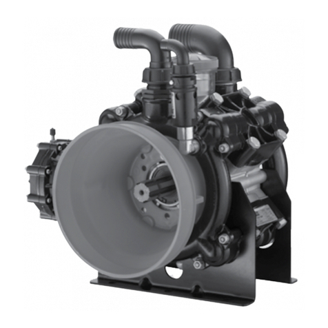
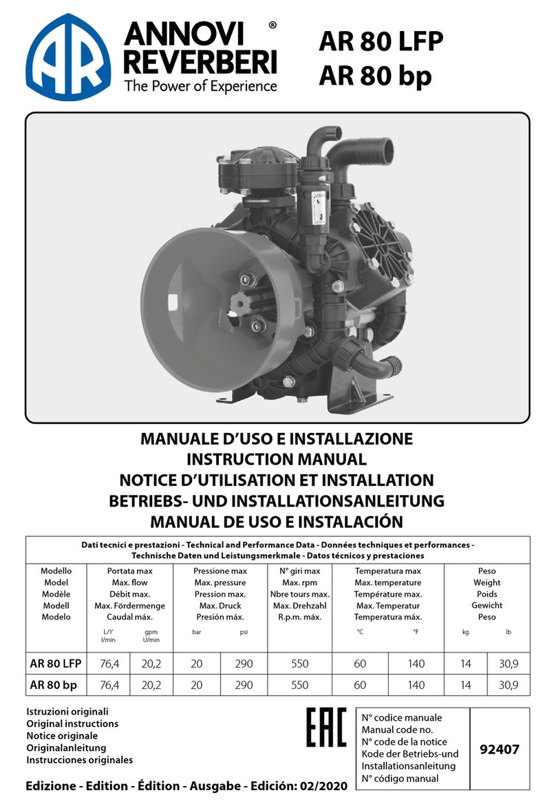
Annovi Reverberi AR 80 LFP User manual

INSTRUCTION MANUAL
AR 80 LFP
AR80LFP - 550
RPm
- S
emi
-H
ydRAuLic
T
HRee
-d
iAPHRAgm
P
umP
m
odeL
m
Ax
gPm m
Ax
L/m
in
m
Ax
PSi m
Ax
B
AR
HP P
oweR
w
eigHT
L
BS
.
AR80LFP-C 20.2 76.4 290 20 3.4 30.8
AR80LFP-SP 20.2 76.4 290 20 3.4 30.8
AR80LFP-AP-SP/C 20.2 76.4 290 20 3.4 30.8
AR80LFP-AP-C/C 20.2 76.4 290 20 3.4 30.8
AR80LFP-GR-GCI* 20.2 76.4 290 20 3.4 40.0
*Model comes standard with Viton diaphragms.
modeL
AR43247 BlueFlex
AR43245 Desmopan
AR43244 NBR
AR43246 Viton
VALVe KiTS
modeL
AR43138 Valves 316SS
o-Ring KiTS
modeL deScRiPTion
AR43128 O-Rings
oiL
modeL deScRiPTion
AR64532D Oil
AR64532D-C Case (6)Oil
diAPHRAgm KiTS
140° F - Max Water Temp 1 1/2”
- Suction
1” - Outlet
140° F - Max Water
Temp 1 1/2” - Suction
1/2” - Hose Barb Outlets
1" - Bypass Hose Barb
Pressure / Bypass
Lever
C Version
1 3/8” 6B Splined Shaft
SP Version
Straight 3/4” Keyed Shaft
AP SP/C Version
Straight 3/4” keyed x
1 3/8 6B Splined Thru
Shaft
AP C/C Version
1 3/8” 6B Splined Thru
Shaft
GR-GCI Version
Pump with Viton® Diaphragms
and Gearbox AR31185 with
3/4” Hollow Shaft and GS25S
Viton® Control Unit
For models AR45, AR60 & AR80
(SP Models Only)
Fits SAE 2-bolt A Flange Motors
with 1” Shaft
utlet
ose Barbs
Bypass
ose
Bar
eote ount
nlet ose Bar
Pressure
ustent no
Full Bypass
Lever Position
Full Pressure
Lever Position
GS35V Control Unit
Model No.AR3249006
INSTALLATION INSTRUCTIONS
Outlet
Hose Barb
2 Places
Bypass Hose
Barb
Remote Mount
Inlet Hose Barb
Red Pressure
Adjustment Knob
Press/Bypass
Lever shown in
Pressure Position
CONTROL UNIT INSTRUCTIONS
1. When starting the pump, keep the control unit in the full bypass position until the pump has
primed.
2. After starting the pump, and after the pump is primed, move the control unit into the
pressure regulation position. Adjust the pressure by turning the red pressure adjustment
knob on the control unit.
3. To stop the pump, reduce the pressure by rotating the lever to the full bypass position.
4. Stop the pump.
IMPORTANT SAFETY INFORMATION
Intended uses
The pump is designed and constructed for incorporation in plants and machinery (spraying machines for the
protective treatment of agricultural crops and garden plants). All other uses constitute misuse unless ap-
proved by the manufacturer's technical service
The pump must be used in a manner appropriate to its technical data (see “Technical Data”), and must not be
modified or improperly used.
Misuses
Do not put the pump into service until the plant or machinery in which it is incorporated has been declared
compliant with the relevant national and local legal requirements.
Do not use the pump in a potentially explosive atmosphere.
Do not use the pump for flammable, toxic or corrosive liquids or liquids with unsuitable density, especially
seawater, adhesives, bitumens, asphalt sealers, two-step curing compounds, concrete sealers, liquefied
gases or solvents of any kind, paints of any kind or liquids containing solids in suspension, and in all cases do
not use with any liquid unless certain that it is compatible with the materials used in the pump circuit.
Do not draw in liquids at temperatures above 50°C or below 5°C.
Do not use the pump in drinking water supply systems.
Do not use the pump on products for human consumption.
Do not use the pump on pharmaceutical products.
Do not use the pump without first checking that the intake and delivery circuit pipelines are correctly secured
and free from leaks.
Do not use the pump without the safety devices provided: guards for shafts and drive couplings and suitably
rated relief valve on the delivery circuit.
Do not use the pump to wash or spray: people, animals or delicate items, live electrical equipment or chemicals
whose characteristics are not known.
Safety devices
Danger - Warning
Never tamper with or by-pass the safety devices. Maintain all safe-
ty devices regularly to ensure they all work efficiently.
The drawing shows the position of the safety devices mounted on the
machine.
Additional safety devices must be added as necessary during the de-
sign phase (see “Installation information”).
A) Fixed guard: provides protection against accidental contacts with
the drive shaft when in operation.
Residual risks
Even if the safety regulations and information provided in the manual
are complied with, the residual risks described in the declaration of
incorporation still apply when the pump is in operation.
A
Installation diagram (guideline)











English language
Use and Installation
5
General guidelines on water supply connection
To operate correctly, the diaphragm pump must draw in liquids from containers at atmospheric pressure.
Do not supply the pump with pressurised liquids.
Forcontinuous duty,thepumpshouldnot drawinwaterbygravityfromcontainerswith liquidlevelatheights
above 3m.
For continuous duty, the pump should not draw in liquids by vacuum from containers with the liquid level
more than 3 m belowthepump intake fitting andthe circuit must consist of hoses of lengthand diameter ap-
propriate tothe pump intakefitting (see “Technical Data”),free from restrictions and elbows, andwith afilter
ofsuitablecapacity (see “Installation”).
Foroccasionalduty,suchasfillingwatersupplytanks,thepumpcanbeoperatedatavacuumdrawinginliq-
uids from reservoirs havingthe surface ofthe liquid upto5 m belowthe pump intake fitting,for periods ofno
more than 15minutes.
Drawing in liquidsfrom lowerlevels or forlongertimes causes cavitation in the pump circuitand re-
duces the lifetimeofthediaphragms,valvesandmechanicalparts.
INSTALLATION INSTRUCTIONS
POSITIVE HEAD
VACUOMETER
ZERO HEAD
ZERO HEAD
Pump is operating
at acceptable
inlet
vacuum
PUMP
WARNING!
MAXIMUM OPERATING
TIME 15 MINUTES
NEGATIVE HEAD
Pump is
operating at
high inlet
vacuum
UN003415-EW
NEGATIVE HEAD
3m (9.8 ft ) m a x
3m (9.8 ft ) m a x
5m (16.4 ft ) m a x













 

















•
•


•

7

H


•
 







 



z

x










      

A


 
 
A/

A

6

5


 
 


 



 
   
  

  

  -
 
  

  

  
   
   






  
30
 















       








/R

P

D

P

P/

64

3

D

       


1) .
  �
C
A
/R
P
ump
O
il
P/
N A
R64
5
32D




 
 




/R

P

S

R64511







A/R Pump Saver
P/N 64511
Protects Pumps from
Freezing Conditions
TROUBLESHOOTING
 




Problem









Cause





















Remedy




























Problem Cause Remedy
 

 
 Stop the pump at once. 
{1)





18 - 2
18 - 3
18 - 5
18 - 1
2021 AR North America
18
18 - 4
A.R. NORTH AMERICAA.R. NORTH AMERICA
AR60LFP / AR80LFP / AR 80 bp
21
15
29
24 23
22
19 20
27
10
27
16
25
26
28
18
Attention!
Assemble with grease
between the plate and
the membrane
30
36
32
35 38
32
31
37
32
34
33
32
30
59
12
17
1
42
39
44
2
41
43
40
11
2
10
2
2
2
2
72
73
13
14
39
50
69
65
66
70
68
67
83
82
65
84
71
60
61
63
62
64
59
70
71
77
79
78
48
49
45
47
46
75
75
74
51
76
80
C
SP/AP
C/AP
SP
Appl. C
18 - 6
2021 AR North America 19
Low pressure
AR60LFP / AR80LFP / AR 80 bp
Pos Code Description Qty Note
45
550040 O-ring Ø 26.65x2.62 2
880311 O-ring Ø 26.65x2.62 2 Viton LFP
46 3460180 Semi air chamber lower 1 Nylon
47
800190 Diaphragm air chamber 1 NBR
800192 Diaphragm air chamber 1 BlueFlex™
48 3460190 Semi air chamber upper 1 Nylon
49 180020 Air valve 1 TT15*.5
50 3460210 Fork 1
51 650542 Gasket 1
59 3240290 Shield 2
60 820672 Bolt TCEI M10x16 4 SS TT90*
61 395870 Washer 4 SS
62 961790 Ring circlip Øi 68 1
63 3120160 Ring seal 1
64 961780 Bearing 1
65 3240320 Ring connecting rod 2
66 3240150 Shaft C marked EE 1
67 3460110 Bearing 1
68 1300230 Ring seal 1
69 480900 Ring circlip Øi 35 1
70 650250 Key 1(d)
71 2280950 Key 1(d)
72 3120690 Plug 3/8”G 1
73
2840890 O-ring Ø 14x2 1
2840591 O-ring Ø 14x2 1 Viton LFP
74 621782 Bolt TE M8x40 6 SS TT180*
75 390315 Washer 12 SS
76 3120260 Nut M8 6 SS TT180*
77 650300 Coupling 1
78 961340 Washer 1
79 680350 Bolt TCEI M8x35 1 TT180*
80
1506 Air chamber NBR 1
43065 Air chamber BlueFlex™ 1
43067 Air chamber BlueFlex™ 1 LFP
81 390315 Washer 6 SS
82 3240170 Shaft
SP/AP marked DM
1 AR80
83 3240160 Shaft C/AP marked EF 1 AR80
84 3240190 Shaft SP marked EB 1 AR80
84 3240180 Shaft 1 AR60
85 3249001 Complete Discharge assembly 1 AR80bp
86 3240180 Shaft SP 1 AR60
87 3249006 Complete Controller 1 Not shown
(a) Bolt with Loctite 242 thread lock STRONG.
(d) Supplied in kit applications.
* Torque: in-lbs +/- 10%
Suggested oil
Type Oz
AR64532D 32
Pos Code Description Qty Note
1 3240030 Manifold valve closed 4
2
390291 O-ring Ø 28.25x2.62 24
390292 O-ring Ø 28.25x2.62 24 Viton LFP
3 3240040 Manifold 3
5 3240050 Manifold asp. threaded 1
6 750670 Ring nut 1 1/2" G 1
7
390290 O-ring Ø 29x3 1
1880460 O-ring Ø 29x3 1 Viton LFP
8 50267 Elbow 1 1/2" 1
9 3240280 Bolt TE M8x55 6 SS TT105*
10 3120760 Washer 36 SS
11 380211 Bolt TE M8x75 12 SS TT90*
12 820672 Bolt TCEI M10x16 4 SS
13
2429050 Valve 6
2429051 Valve AISI 316L 6 LFP
14
3460240 Gasket 6
3460380 Gasket 6 Viton LFP
15 3240020 Head 3
16 621771 Bolt TE M8x80 24 SS TT125*
17 395870 Washer 4 SS
18 3120510 Nut M8 12 SS
19
3240100 Hub pin AISI 303 3 TT265* (a)
3240101 Hub pin AISI 316L 3 LFP TT265* (a)
20 320622 Washer 3 SS
21
2240110 Nut M10 AISI 304 3 TT220*
2240670 Nut M10 AISI 316L 3 LFP TLFP T220*
22 3240110 Retaining washer 3
23
1040081 Diaphragm 3 NBR
1040083 Diaphragm 3 BlueFlex™
1040080 Diaphragm 3 Desmopan
1040082 Diaphragm 3 Viton
24 3240130 Sleeve 3
25 650190 Piston ring 1
26 1040120 Piston Ø 63 3
27 1040270 Ring circlip Øi 15 2
28 1040070 Pin 3
29 3240120 Connecting-rod 3
30 3240090 Base 2
31 3240010 Pump body 1
32 620342 Bolt TE M10x20 4 SS TT265*
33 880530 Plug 3/8”G 1 TT180*
34 740290 O-ring Ø 14x1.78 1
35 720030 O-ring Ø 22.22x2.62 1
36 3120240 Oil sight glass 1 TT180*
37 650920 O-ring Ø 53.65x2.62 1
38 1040324 Plug rosso 1
39 3240031 Manifold 2
40 3240060 Manifold 1
41 3120440 Ring nut 1” G 1
42
1140450 O-ring Ø 20.24x2.62 1
1140451 O-ring Ø 20.24x2.62 1 Viton
43 3120460 Elbow 1" 1
44
3240070 Manifold 1 For pulsation damper
3240080 Manifold 1 For GS35 contoler
AR 43247
BlueFlex diaphragms
AR 43244
NBR diaphragms
AR 43246
Viton diaphragms
AR 43245
Desmopan diaphragms
Pos. Qty
14 6
23 3
45 2
47 1
AR 42805
Valves - AR80bp
AR 43138
Valves - AR80LFP
Pos. Qty
13 6
14 6
AR 42857 - AR 80 bp
AR 43128 - AR 80 LFP
O-Rings
Pos. Qty Pos. Qty
224 45 2
7 1 52 1
34 157 1
35 158 1
37 173 1
42 1
Pump and
manufacturer
identication.
Crankcase Oil
Capacity 13 oz
C SP GR3/4-GCI GR-GCI AP-C/C AP-SP/C
AR60LFP 33154 33047
AR80LFP 32010 33086 33037 32013 32012
AR80bp 31693 31694 31696
16 - 2
16 - 3
16 - 5
16 - 1
2021 AR North America
16
16 - 4
A.R. NORTH AMERICAA.R. NORTH AMERICA
OUT
47
48
49 50
51
52 53
54
56
57
58
55
59
60
61
62
63
64
65 66
65 67
68 69 70
72
72 71
71
75
74
73
74 73
65
9
8
∆
47
2
2
3
2
1
23
2
5
6
2
4
74
73
81
80
21
22
19
15
20 22
23
24 25 26 27
29
30
31
33
32
10
11
12
13 Warning!
Fit with molybdenum disulde grease
between plate and diaphragm.
37
39
38
37
36
35
34
40
41
42
42
43
2
3
2
4
3
2
2
2
4
44
45
46
9
8
IN
64 68
71
85
85
72
69
64
65
65 64
64
66
67
91
89
90
73
74
76
77
78
80
79
75
81
83
83
82
82
83
84
82
87
88
92
70
Suggested Oil
Type Oz
90W Gear Lube 14
c
o
d
.
3
1
1
8
5
Gear Box AR31185
AR 60LFP GR-GCI / AR 80LFP GR-GCI
2021 AR North America 17
Low pressure
Pos Code Description Qty Note
13240031 Manifold 3/8" G 1
2390292 O-ring Ø 28.25x2.62 24 Viton
33240040 Manifold 4
43240030 Manifold 5
5380211 Bolt 12 SS T88*
63120760 Washer 12 SS
73240080 Manifold 1
83460380 Gasket 6Viton
92429051 Valve AISI 316L 6
10 720030 O-ring Ø 22.22x2.62 1
11 3120240 Oil reservoir 1T177*
12 650920 O-ring Ø 53.65x2.62 1
13 1040322 Plug 1
15 3240010 Pump body 1
16 620342 Bolt TE M10x20 4SS T265*
17 880530 Plug 3/8" G 1T177*
18 740290 O-ring Ø 14x1.78 1
19 3240120 Connecting-rod 3
20 1040120 Piston Ø 63 3
21 1040070 Pin 3
22 1040270 Ring Circlip Øi 15 6
23 650190 Piston ring 3
24 3240140 Sleeve 3
25 1040082 Diaphragm Øe 105 3 Viton
26 3240110 Plate 3
27 3240101 Hub pin AISI 316L 3T265* (a)
29 2240670 Nut M 10 AISI 316L 3 T177**
30 3240020 Head 3
31 3120510 Nut M8 12 SS
32 3120760 Washer 24 SS
33 621771 Bolt TE M8x80 24 SS T124*
34 480900 Ring Circlip Øi 35 1
35 1300230 Ring 1
36 3460110 Bearing 1
37 3240320 Ring 2
38
3240180 Shaft 1AR60LFP
3240190 Shaft 1AR80LFP
39 2280950 Key 1
40 961780 Bearing 1
41 3120160 Ring 1
42 961790 Ring Circlip Øi 68 1
43 3240050 Manifold 1
44 750670 Ring nut 1-1/2" G 1
45 1880460 O-ring Ø 29x3 1 Viton
46 50267 Elbow Ø 40 1
47 3240440 Knob 1
48 3240410 Spring 1
49 480441 O-ring Ø 17.13x2.62 1Viton
50 3240380 Piston 1
51 391001 O-ring Ø 9.13x2.62 1 Viton
52 1880210 Ring nut 1
53 961240 O-ring Ø 31.47x1.78 1
54 3240360 Body 1
Pos Code Description Qty Note
55 1880240 Pin 1
56 660171 O-ring Ø 31.42x2.62 1
57 394211 O-ring Ø 29.82x2.62 1Viton
58 3240391 Piston 1
59 3240421 Plug 1
60 720031 O-ring Ø 22.22x2.62 1Viton
61 3120460 Elbow Ø 25 1
62 1140451 O-ring Ø 20.24x2.62 1 Viton Green
63 3120440 Ring nut 1" G 1
64 3240350 Box 1
65 3460210 Fork 3
66 1880340 Pressure gauge Ø 50 1 to 50 bar
67 1880250 Fitting 1
68 2840891 O-ring Ø 14x2 1Viton Green
69 400441 O-ring Ø 17.13x2.62 2 Viton
70 3240450 Body 1
71 110130 Ring nut 1/2" G 2
72 1880492 Valve 3/8"G-1/2"GM-M SX 2
73 2840891 O-ring Ø 14x2 3 Viton Green
74 3120690 Plug 3/8" G 3T17*
75 50351 O-ring Ø 23.81x2.62 2Viton
77 961800 Ring 1
78 961790 Ring Circlip Øi 68 1
79 881090 Key 1
80 3240280 Bolt TE M8x55 6SS C12
81 390315 Washer 6SS
83 1980740 Plug Brass 3/8" G 3 T177*
84 1140370 Plug 1
85 540300 Bolt TCEI M10x30 8T217*
87 1380630 Key 1
88 651000 Bolt TCEI 5/16" 24 UNF 1" 4 T217*
89 620470 Bolt TCEI M10x20 3T177*
90 200231 Washer 3
91 880280 Bolt TCEI M6x18 1T88*
92 780230 Washer 1
98 180030 Bolt TCEI M8x20 1T217*
99 620950 Gasket 1
100 651620 Gear Z=64 1
101 3120350 Shaft 1
102 3120360 Gasket 1
103 320240 Ring Circlip Øe 40 2
104 620960 Box 1
105 620990 Bearing 1
106 621660 Pinion Z=11 1
107 740290 O-ring Ø 14x1.78 3
108 961780 Bearing 1
109 3120340 Flange 1
110 3240090 Base 2
(a) Bolt with Loctite 242 thread lock STRONG
* Torque: in-lbs +/- 10%
AR 42804
BlueFlex diaphragms
Pos. Qty
25 3
AR 43138
Valves
Pos. Qty
8 6
9 6
Suggested Oil
Type Oz
AR64532D 32
AR 60LFP GR-GCI / AR 80LFP GR-GCI
Pump and
manufacturer
identication.
Crankcase Oil
Capacity 13 oz
AR 42995
O-Rings
Pos. Qty Pos. Qty
224 57 1
8 6 60 1
12 162 1
18 168 1
45 169 2
51 173 3
56 1
2018 AR North America 93
Gear boxes
A.R. NORTH AMERICA
93 - 1
Pos Cod. Description Q.ty Note
13120360 Gasket 1
23120340 Flange 1
3620960 Body 1
43120350 Shaft 1
AR45bp-AR80bp
5780230 Washer 1
6880280 Bolt
TCEI M6x18
1 T90*
7651620 Gear
Z=64
1
8620470 Screw
TCEI M10x20
3 T180*
9620950 Gasket 1
10 1140370 Plug 1
11 1980740 Plug
3/8” G ottone
3T180*
12 740290 O-ring
Ø 14x1,78
3
13 651000 Bolt
TCEI 5/16” 24 UNF 1”
4
Geomet
T220*
14 540300 Bolt
TCEI M10x30
8 T220*
15 620990 Bearing 1
16 621660 Pinion
Z=11
1
17 320240 Ring
seeger Øe 40
2
18 961780 Bearing 1
19 881090 Key 1
20 961790 Ring
seeger Øi 68
1
21 961800 Ring
tenuta
1
22 3120350 Key 1
AR45bp-AR80bp
23 180030 Screw
TCEI M8x20
1T220*
24 1380630 Key
di manovra
1
25 200231 Washer 3
Suggested Oil
For gas engine with Ø3/4" shaft, flange SAE J609a
*Torque: in/lbs +/- 10%
1
2
4
5
6
7
8
10 9
11
12
11
12
13
11
12
15
16
17
18
17
20
21
3
23
25 24
19
22
AR 31185 : Gear Reduction
Use of engine :
31185:
B&S Vanguard 6.5
Kohler SH265 - CH270
Subaru E17 - 21
Honda GP160 - GX160
Ø 3/4" Straight Keyed Shaft
Type
90 W Gear Lube
14
I
1.Lubricate the gasket (Ref. 1) on the pump adapter flange (Ref. 2). Slip the flange
over the machined surface of the casting, shaft end of pump. Install (4) mounting
bolts (Ref. 14) through the adapter flange into the pump body.
2. Install the shaft hub (Ref. 4) on the pump shaft, after inserting the key (Ref. 22).
Secure the hub by threading the retaining bolt (Ref. 6) through the retaining
washer (Ref. 5) into the pump shaft.
3.Install the pump gear (Ref. 7) with the pilot diameter of the gear inserted into
the inner diameter of the pump shaft. Secure firmly onto the shaft using M10 x
25 socket head cap screws (Ref. 8) and lock washers (Ref. 25).
4.Align the holes in the pump adapter flange (Ref. 2) with threaded holes in the
gearbox body. Lubricate the gasket (Ref.9) and place it in position on the
gearbox body (Ref. 3). Install the gearbox body (Ref. 3) on the pump adapter
flange (Ref. 2) and secure firmly with M10 x 75 socket head cap screws (Ref. 14).
Install the M8 x 20 socket head cap screw (Ref. 23) and tighten securely.
5.Insert the long key (Ref. 19) into the engine shaft keyway. Apply anti-seize to
the motor shaft. Align the keyway in the gear reducer input shaft (Ref. 16) and
slide the pump and gear reducer onto the engine shaft.
6.Align the holes in the gearbox body with threaded holes in engine boss. Insert
5/16”x1”-24 socket head cap screws through the gearbox body (Ref. 3) and
thread them into the threaded holes in the engine boss. Securely tighten with
the hex wrench provided.
7.The vent plug (Ref. 10) must always be installed in the uppermost threaded
hole of the gearbox body (Ref. 3).
8.Fill the gear case with 90W gear lube. To properly fill, first tighten the bottom
plug (Ref. 11); then remove one side plug (Ref. 11) and the vent plug (Ref. 10). Fill
until the gear lube is no higher than the mark on the dipstick.
9.Replace and tighten the side plug and the vent plug.
14
I
2020 AR North America 81
Control units
A.R. NORTH AMERICAA.R. NORTH AMERICA
81 - 1
AR 42834
Maintenance repair
Pos. Qty Pos. Qty
4 1 26 1
5 1 27 1
7 1 28 1
8 1 29 2
10 130 1
11 2
16 2
17 2
22 2
25 1
GS 35 S
11
11
12 13
14
21 21
27
10
18
19
20
30
24
24
21
23
22
33
15
16
4
28
9
6
24
32
31
24
16
17
29
17
29
26
3
25
2
1
57
8
(A)
WARNING! Time the two holes using
the tooth indicated in the position (A)
@
AR 42833
O-Rings
Pos. Qty Pos. Qty
8 1
10 1
22 2
25 1
26 1
27 1
28 1
29 2
30 1
Pos Code Description Qty Note
1 3240440 Knob 1
2 3240410 Spring 1
3 3240380 Piston upper 1
4 1880240 Pin 1
5 3240390 Piston lower 1
6 1880210 Ring nut 1
7 3240420 Plug 1
8
720030 O-ring Ø 22.22x2.62 1
720031 O-ring Ø 22.22x2.62 1 Viton
9 3240360 Body regulator 1
10
660170 O-ring Ø 31.42x2.62 1
660171 O-ring Ø 31.42x2.62 1 Viton
11 3460210 Fork 2
12 3240470 Pressure gauge 1 0-725 PSI
13 280080 Screw TCEI M8x60 2
14 380241 Washer 2
15 3240430 Body 1
16 3120460 Elbow Ø 25 2
17 3120440 Ring nut 1” G 2
18 320406 Bracket 1
19 390270 Nut M8 2 TT90*
20 3120690 Plug 1
21 1880492 Ball valve
3/8”G - 1/2”G M-M SX
3
22
480440 O-ring Ø 17.13x2.62 2
480441 O-ring Ø 17.13x2.62 2 Viton
23 3240450 Body regulator 1
24 110131 Ring nut / HB 1/2”x 3/8" 4
24 110130 Ring nut / HB
1/2" x 1/2"
4Optional
25
480440 O-ring Ø 17.13x2.62 1
480441 O-ring Ø 17.13x2.62 1 Viton
26
391000 O-ring Ø 9.13x2.62 1
391001 O-ring Ø 9.13x2.62 1 Viton
27
1520650 O-ring Ø 29.82x2.62 1
394211 O-ring Ø 29.82x2.62 1
28 961240 O-ring Ø 31.47x1.78 1
29
1140450 O-ring Ø 20.24x2.62 2
1140451 O-ring Ø 20.24x2.62 2 Viton
Pos Code Description Qty Note
30
2840890 O-ring Ø 14x2 1
2840891 O-ring Ø 14x2 1 Viton
31 1880250 Fitting 1
32
2840890 O-ring Ø 14x2 1
2840891 O-ring Ø 14x2 1 Viton
33 1880491 Ball valve
3/8”G - 1/2”G M-M DX
1
34 3249006 Direct mount assembly
complete
1Not shown
(A) Holes datum rib
@ Pump and manufacturer identication.
* Torque: in-lbs +/- 10%
GS35S 915
GS35SV 916

This manual suits for next models

5

Other Annovi Reverberi Water Pump manuals

Annovi Reverberi AR 713 User manual

Annovi Reverberi

Annovi Reverberi AR 713 User manual

Annovi Reverberi BHS 130 User manual

Annovi Reverberi

Annovi Reverberi BHS 130 User manual

Annovi Reverberi AR70BP User manual

Annovi Reverberi

Annovi Reverberi AR70BP User manual

Annovi Reverberi AR 3.8 DFL Installation instructions

Annovi Reverberi

Annovi Reverberi AR 3.8 DFL Installation instructions

Annovi Reverberi AR 125 bp User manual

Annovi Reverberi

Annovi Reverberi AR 125 bp User manual

Annovi Reverberi AR70BP User manual

Annovi Reverberi

Annovi Reverberi AR70BP User manual

Annovi Reverberi BHS 75 User manual

Annovi Reverberi

Annovi Reverberi BHS 75 User manual

Annovi Reverberi XJS User manual

Annovi Reverberi

Annovi Reverberi XJS User manual

Annovi Reverberi AR 80 bp User manual

Annovi Reverberi

Annovi Reverberi AR 80 bp User manual

Annovi Reverberi AR 45 LFP User manual

Annovi Reverberi

Annovi Reverberi AR 45 LFP User manual

Annovi Reverberi AR 250 bp User manual

Annovi Reverberi

Annovi Reverberi AR 250 bp User manual

Annovi Reverberi BHS 170 User manual

Annovi Reverberi

Annovi Reverberi BHS 170 User manual

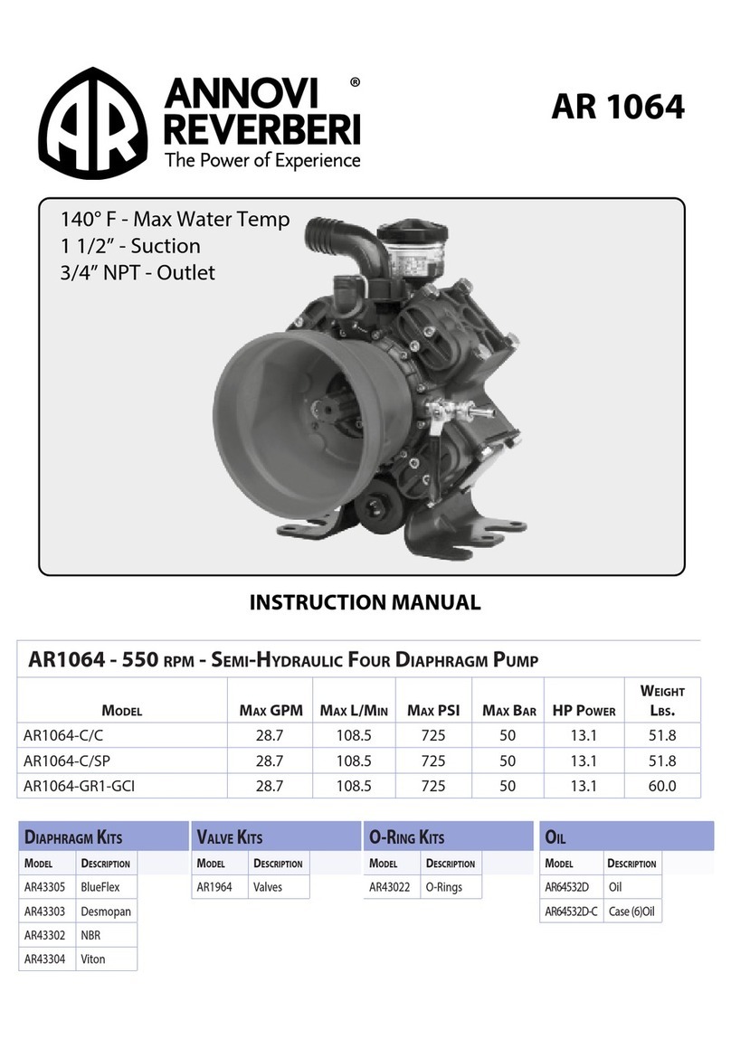
Annovi Reverberi AR160LFP-C/C User manual
Annovi Reverberi

Annovi Reverberi AR160LFP-C/C User manual

Annovi Reverberi AR1064-C/C User manual

Annovi Reverberi

Annovi Reverberi AR1064-C/C User manual

Annovi Reverberi BHA 130 User manual

Annovi Reverberi

Annovi Reverberi BHA 130 User manual

Annovi Reverberi AR202 User manual

Annovi Reverberi

Annovi Reverberi AR202 User manual
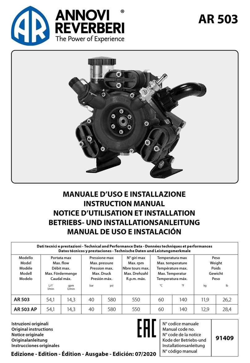
Annovi Reverberi BHP 170 User manual

Annovi Reverberi

Annovi Reverberi BHP 170 User manual

Annovi Reverberi AR 5.7 DFL Installation instructions

Annovi Reverberi

Annovi Reverberi AR 5.7 DFL Installation instructions

Annovi Reverberi Power Garden CAR 50 User manual

Annovi Reverberi

Annovi Reverberi Power Garden CAR 50 User manual

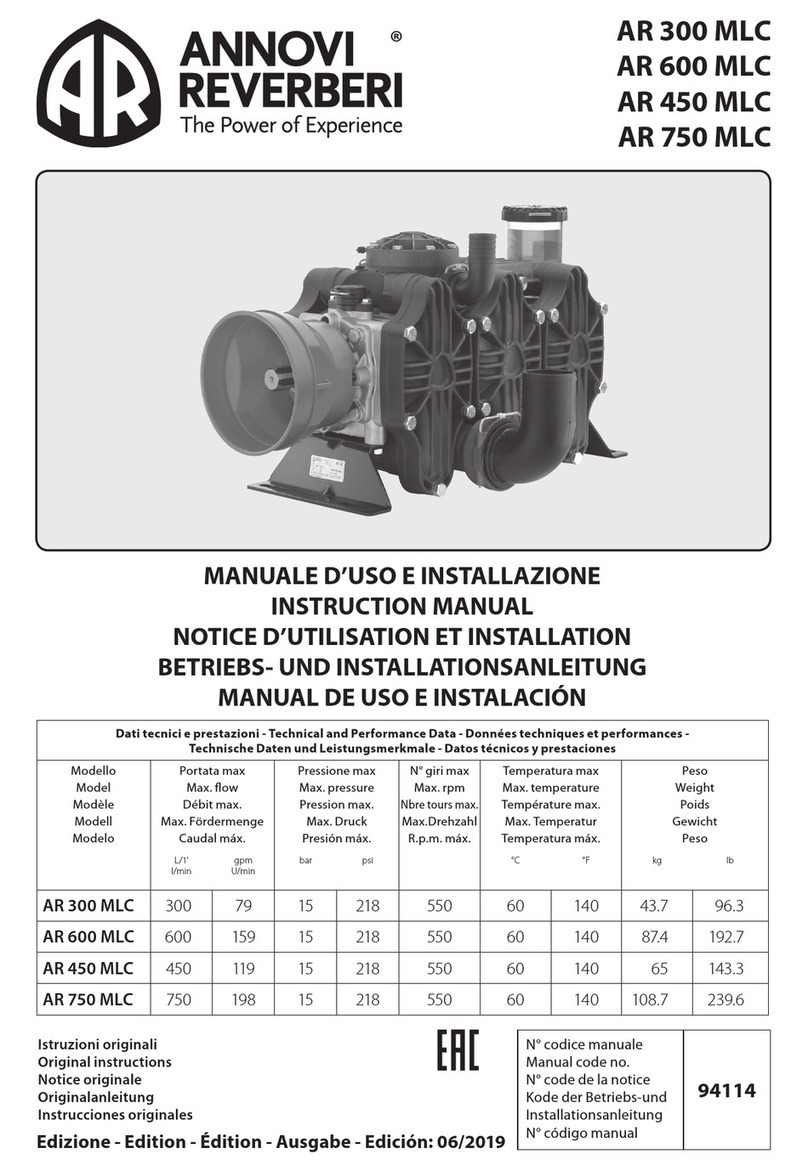
Annovi Reverberi AR 503 AP User manual
Annovi Reverberi

Annovi Reverberi AR 503 AP User manual

Annovi Reverberi AR 60 LFP User manual

Annovi Reverberi

Annovi Reverberi AR 60 LFP User manual

Annovi Reverberi AR 303 User manual

Annovi Reverberi

Annovi Reverberi AR 303 User manual

Annovi Reverberi AR 245 LFP User manual

Annovi Reverberi

Annovi Reverberi AR 245 LFP User manual

Annovi Reverberi CR Series User manual

Annovi Reverberi

Annovi Reverberi CR Series User manual

Popular Water Pump manuals by other brands

Gilian Gil Air Plus manual

Gilian

Gilian Gil Air Plus manual

BUSCH Mink MV 1202 A instruction manual

BUSCH

BUSCH Mink MV 1202 A instruction manual

Kohler TP 3.0 owner's manual

Kohler

Kohler TP 3.0 owner's manual

Burcam 300910 installation instructions

Burcam

Burcam 300910 installation instructions

Fala 75945 manual

Fala

Fala 75945 manual

Viking pump 4223AX Series Technical & service manual

Viking pump

Viking pump 4223AX Series Technical & service manual

Alpha tools AL 9,6 operating instructions

Alpha tools

Alpha tools AL 9,6 operating instructions

SPERONI RSM 3 operating instructions

SPERONI

SPERONI RSM 3 operating instructions

Simrad RPU80 instruction manual

Simrad

Simrad RPU80 instruction manual

Samoa 560 230 Technical service guide

Samoa

Samoa 560 230 Technical service guide

CEG ECOJET 500PC Installation and operating instruction manual

CEG

CEG ECOJET 500PC Installation and operating instruction manual

Espa ACUARIA37 4 instruction manual

Espa

Espa ACUARIA37 4 instruction manual

Pentair Pool Products SW Use and maintenance manual

Pentair Pool Products

Pentair Pool Products SW Use and maintenance manual

Piusi SQUALO35 Use and maintenance manual

Piusi

Piusi SQUALO35 Use and maintenance manual

Calpeda MXP Series operating instructions

Calpeda

Calpeda MXP Series operating instructions

SKC Flite4 operating instructions

SKC

SKC Flite4 operating instructions

Dover PSG WILDEN P2 Series PSG WILDEN... Engineering, operation & maintenance

Dover

Dover PSG WILDEN P2 Series PSG WILDEN... Engineering, operation & maintenance

Greenlee Fairmont H4660B Service manual

Greenlee

Greenlee Fairmont H4660B Service manual

manuals.online logo
manuals.online logoBrands
  • About & Mission
  • Contact us
  • Privacy Policy
  • Terms and Conditions

Copyright 2025 Manuals.Online. All Rights Reserved.