DUUN VM410 User manual

VM410 Instruction manual
Duun Industrier as
7630 Åsen, Norway
www.duun.no

2
Congratulations on your Duun VM410 firewood processor.
All Duun tractor operated machines have been engineered and tested in close cooperation with
representative users to produce functionally safe and user-friendly machines.
Please read this instruction manual before using the machine.
Good luck!
Machine identification
Serial number and manufacturer are indicated on badge (A).
Register serial number and delivery time as indicated.
Always specify serial number when requesting service for the machine.
The machine is CE-marked (B). This marking confirms that the machine has been manufactured in
conformity with EU Directive Machinery.
Serial number
Time of delivery (month/year)

3
CONTENT
MACHINE INDETIFICATION 2
SAFETY 4
WARRANTY TERMS 8
DELIVERY FORM OF DUUN FIREWOOD PROCESSOR 9
TECHNICAL DATA 10
TRANSPORT AND HANDLING PRIOR TO USE 12
TRANSPORT AND HANDLING BEFORE USE 12
PREPARATION FOR MOVEMENT BY TRACTOR 12
TRANSMISSION SECURITY 12
HYDRAULIC OIL QUALITY 13
OIL LEVEL CONTROL 13
OIL TEMPERATURE CONTROL 13
CONDENSATION CONTROL 13
POWER TRANSMISSION SHAFT 14
TRANSPORTER PREPARATION 14
FEEDING BELT PREPARATION 15
SIDE ADJUSTMENT OF CONVEYOR 15
ADJUSTMENT OF THE CUTTING LENGHT 15
HEIGHT ADJUSTMENT 15
PRACTICAL USE 16
CONDITIONS 16
START-UP AND APPROPRIATE SPEED 16
ACTIVATION OF ELETRICAL CONTROL 16
THE MAIN FUNCTIONS-FEEDING-CONVEYOR BELT SPEED REGULATION 17
CUTTING ADJUSTMENT 17
CONVEYOR BELT SPEED 17
HYDRAULIC KNIFE LIFT 18
MANUAL KNIFE LIFT 18
CUTTING 18
SAW CHAIN OIL FILLING 18
SAFE MANUALLY OPERATED LOG HOLDER 19
STUCK MATERIAL 19
CHAIN SHARPENING AND TIGHTENING 20
ADJUSTMENT OF THE CHAIN LUBRICATION 21
SERVICE AND MAINTENANCE 22
DAILY MAINTENANCE 22
WEEKLY MAINTENANCE 23
MONTHLY MAINTENANCE 24
ANNUAL MAINTENANCE 24
DECLARATION OF CORNFORMITY 29

4
Safety
All operators, mechanics and the owner must always work carefully with agricultural machinery. Read
and observe safety instructions in this instruction manual.
Be particularly aware of warning signs with this symbol, it marks measures
that must be carried out in order to avoid accidents. The symbol appears in
the instruction manual and on warning signs on the machine.
Instruction manual
All operators, mechanics and the owner must be
well acquainted with the instruction in this
instruction manual before the machine is taken
into use.
Safety of the surroundings
Be very careful when other people or animals
are near the machine or tractor. Never stand
between the tractor wheels and the machine!
Protective equipment
Always wear hearing protection and safety
glasses when using the firewood processor.
Furthermore, safety shoes and sturdy work
gloves should be used when operating the
machine and materials.
Clothing and Power transmission shaft
Do not work in clothing that can be pulled into
moving parts of the machine (e.g. scarves, long
coats).
The tractor is disengaged and the handbrake is
applied before the shaft is connected to the
tractor's PTO. The maximum power output
speed is 400 rpm. The drive shafts are always to
be equipped with original protection covers.
Damaged and worn covers are to be replaced
immediately! Make sure that all covers for the
shaft are in good condition and correctly fitted.
Never start the machine when this is not in
order. The locking chains for the plastic covers
are always to be fixed to the appropriate
brackets in order to prevent the covers to rotate.

5
Safe connection and use
Do not allow anyone to stay between the
machine and the tractor when the machine is
connected to the tractor. The same applies
during the use of the machine. Make sure that
the connection is carried out in a safe manner.
Safety in case of interruptions and
maintenance
Remember always to stop the tractor’s engine
and remove the ignition key before you lubricate,
adjust, clean, or carry out repairs. This is to
secure that the tractor does not start before you
have completed the operation.
Hydraulic high fluid pressure
Be careful when you work with hydraulics. Wear
eye protection and gloves. Hydraulic oil under
high pressure may penetrate the skin and cause
serious infections. See a doctor if you have
sustained an injury. Make sure no one is close by
when performing hydraulic functions.
Danger of crushing at marked points
Pay particular attention to the risk of crushing at
points marked for this.
0-promille
People under the influence of alcohol cannot
opperate the machine. The same applies for tired
people who do not have full control over their
movements.

6
Contact with current-carrying cables etc.
during transport.
Please note that the firewood processor can tip
over the tractor during transport and there is a
risk of contact with live wires, railway
underpasses etc.!
Conveyor belt –transporter
Do not stay under the conveyor when it is
tensioned to avoid damage of an uncontrolled fall
during use. Also avoid contact with the
conveyor's moving parts during use.
Horizontal placement and tidiness
Always place the machine as level and stable as
possible to ensure stable working conditions.
Keep the workplace as tidy as possible. This
contributes to generally better security against
unwanted incidents.
Purpose of use
The machines are only intended for the
production of firewood from branched material
without other extraneous objects. It is not
permitted to use the machine for other material
such as construction waste and similar material
with metal objects such as nails, screws or
similar things. The same applies to material
contaminated with plaster and similar coatings.
The saw chain is only intended for materials
without extraneous objects.
The necessity of good lighting
The machine is used only in daylight, which
ensures a good overview of the operations -
otherwise, with artificial lighting, which gives a
good view of the working area.
Good lighting is very important for the safety
reasons.

7
Safe transportation
Before the machine is moved, the feed belt and
conveyor (both in the folded-up position as
outlined) must be strapped together with a load
strap to ensure that they cannot fall down. The
loading stop has an attachment at the bottom of
the feed belt and secures the belt from falling off
during transport.
Safe cutting
Avoid using your hands near the saw chain. This
is achieved by consistently using the log holder A
and the handle Bfor operating it.
Cutting the last log, it is important to keep a
"correct" long one at the end and cut a shorter
piece of wood as the penultimate one. During this
operation, it is particularly important to use the
manual log holder Athat the user does not
receive unexpected blows from the last length.
It is a great advantage to use the "countdown
ruler" for the last three lengths that these can be
cut to a shorter length than the desired length.
Cutting a twiggy or a crooked logs, it is important
to ensure that these are not left unattended.
Cutting such wood, use the manual log holder A
as often as possible to avoid pinching your
fingers/hands.
Before starting up after maintenance, check that all tools have been removed and replaced.
Before raising or lowering the machine, check that no one is near or touching the machine
If warning signs are removed during repairs or service, new signs must be installed
immediately!

8
Warranty terms
Duun VM410 has 12 months guarantee against defects in materials and workmanship.
Parts that are not originally manufactured by Duun Industrier as, for example, wheels, hydraulic parts,
etc. are subject to these suppliers’ guarantees and terms.
Parts that are considered wearing parts are not included in the warranty - these are specified in a
separate table at the bottom of this page.
In cases where a repair is considered to be included as a matter of warranty, the representative must
inform the supplier's representatives that the repair is thought to be carried out as a matter of
warranty.
The following information must be registered in this connection:
•The product designation
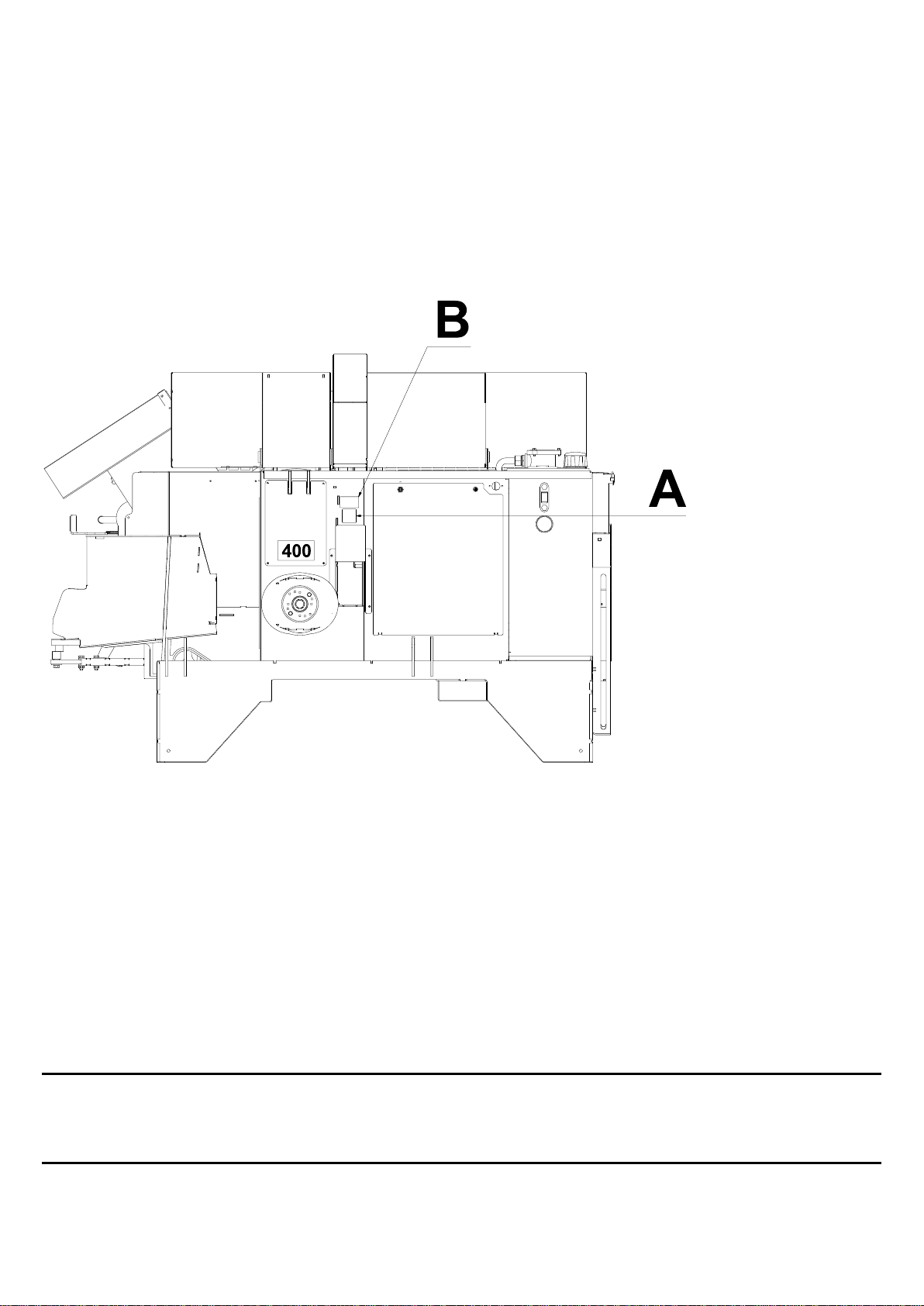
•The product's serial number. (see machine identification p.2)
•Date of sale
•The product owner address, tel. no.
•The seller with address, tel. no.
In case of such a repair, the supplier is presented with a claim within 3 weeks after the repair date.
Replaced parts are to be kept until a decision has been made with reference to the claim and the
replaced parts are to be forwarded to Duun Industrier as for assessment if so required.
As the employment of the product is beyond our control, we may only guarantee the quality and do
not accept liability for the product's general performance.
Warranty liability requires that scheduled maintenance be done.
Duun Industrier as reserves the right to modify the design and specifications and/or make alterations
and improvements without notification.
What is not included in the guarantee:
•The guarantee does not cover financial loss as a result of interruption of operation.
•The guarantee does not cover consequential loss due to defects.
•The guarantee does not cover defects or damage caused by misuse and uses that are not in
accordance with the instruction manual’s specifications and guidelines.
The following parts and materials are considered wearing parts and are not covered by
warranty:
•Chain saw bar
•Chain saw
•Splitting knives
•Feeding belt
•Oil filter
•Hydraulic oil

9
DELIVERY FORM OF DUUN FIREWOOD PROCESSOR
MACHINE INFORMATION
Model _ _ _ _ _ _ _ _ _ _ _
Serial no. _ _ _ _ _ _ _ _ _ _ _
CUSTOMER INFORMATION
Machine owner _ _ _ _ _ _ _ _ _ _
Address _ _ _ _ _ _ _ _ _
Aip code. _ _ _ _
Town _ _ _ _ _ _ _ _ _
DELIVERY OF THE MACHINE
Seller and customer have together checked the machine is not damaged during transportation and that all equipment is
included.
The customer has been made aware of the use of the machine:
-How to prepare machine for use from transport position.
-Correct length of PTO shaft. (page 14)
-How to control the temperature and oil level. (page 13)
-How to control condensation level on the oil tank. (page 13)
-What is the correct speed of the power transmission. (page 16)
-The functions of the machine.
Input: (page 17)
Cutting: Adjusting the speed and power of the chain saw bar. (page 17)
Sharpening and tightening of the chain. (page 20)
Adjustment of the chain lubrication. (page 21)
Use of the log holder. (page 19)
Splitting: Return function of splitters. . (page 19)
Elevation of splitting knives and change og splitting knives. (page 18)
Conveyor: Adjustment of speed. (page 17)
Sideward movement of conveyor. (page 14)
Sales representative and customer have read about service and maintenance. (page 20-24).
The customer has been introduced to warranty terms. (page 8)
The customer is made aware of the conditions for practical use. (page 16)
Part list is available at sale representative.
Place _ _ _ _ _ _ _
Date _ _ _ _ _ _ _
Customers signature Sales representatives signature
_ _ _ _ _ _ _ _ _ _ _ _ _ _ _ _ _ _ _ _ _

10
Technical data
Features:
VM410
Max cutting diameter
41 cm
Max splitting force
11000 kg
Chain drive
Hydraulic
Cutting length
20-50 cm
Saw chain type
1,6 mm
Chain speed
23 m/s
Saw chain pitch
0,325"
Total saw chain links
85 links
Weight
Approx. 900 kg
Moving log stopper
Yes
Log holder
Hydraulic
Height of work table F
880-960 mm
Support legs
Standard 0-40-80 mm
Splitting knife
8 - piece
Rinsing conveyor
Yes
Swa chain lubrication
Separate pump
Knife adjustment
Hydraulic
Number og hydraulic pumps
3
Feeding belt A
Hydraulic
Conveyor length B
4000 mm
Conveyor movement
sideways D
25° to each side
Maximum height E
2540 mm
Maximum width C
2400 mm
Depth transport position
1500 mm
Saw chain oil container
2,5 litres
PTO speed
400 rpm
Oil tank volume
75 litres
Asseccories
Article number
4- part splitter
14131128
6- part splitter
14131035
Adjustable support legs
141309131
Triangel quick connection
1252637
HMV quick connection
1252638
Manual Log rack
141409001
Hydraulic Log rack
141409002
Output step feeder

11

12
Transportation and handling before use
Transport and handling before use
The hull for the VM410 is equipped with a fork
pocket (A) for handling with a forklift or pallet
forks. Be aware that a single firewood machine
weighs approximately 900 kg. Use lifting
equipment designed for such a total weight!
Preparation for movment by tractor
The transporter is folded together in the joint E.
The conveyor is then pulled to a vertical position
using the winch wire. During this process, the
protection cover is shifted in point B. Feeding
table and the conveyor belt are adjusted to a
vertical and horizontal position by releasing the
locking pin in point G.
Transmission security
Ultimately, the connection between the feeding
table and the conveyor is secured with a
tensioning strap for this with attachment at points
as illustrated. This is important to ensure that the
feeding conveyor is kept in place during transport
and the connection between the feeing table and
the transporter is safely secured.

13
Hydraulic oil quality
The machines' ability to function will mostly
depend on the hydraulic oil being intact.
The biggest dangers to the oil quality are:
•Excessively high temperature which
entails poor lubrication performance and
risk of faults and break-down of expensive
components such as valves, pumps and
motors.
•Condensation which is formed during
conditions including humid air combined
with temperature fluctuations. (the oil tank
breathes through the filter and pull in
humid air).
•Condensation water in the oil has the
same effect as excessively high oil
temperature. Condensation appears
mainly during the use in conditions
involving humid air and temperature
around 0°C. The oil tank is equipped with
a draining plug for changing oil and
checks for condensation.
Oil level control
The machines are filled with 75 liters of hydraulic
oil from the factory. Recommended oil quality is
ISO VG46 (viscosity group 46). Examples of
such oils are Mobil DTE15m and Statoil
Hydraway HVXA46.
The oil level is checked by observing the level
glass A, which is in the intake grid of the
hydraulic tank.
Oil temperature control
It is very important to keep control of the oil
temperature Band avoid situations where it
exceeds 70 degrees. This situation may occur
during unfavourable operating conditions for
example in case of too high rotational speed
during the use. The pto speed should under no
circumstances exceed 400 rpm.
The processor has a built in temperature control
device which stops machine functions if the oil
temperature rises too high. Stop the machine and
cool it off before further operation.
Condensation control
The oil tank is equipped with a drainage plug C in
the bottom. Grey oil is an indication of water in
the oil. In case the oil is polluted with water, all
the hydraulic oil must be changed.
Beyond such conditions, the hydraulic oil must be
changed every year or after 500 operating hours
(whatever occurs first).

14
Power transmission shaft
The power transmission shaft is maintained and used in accordance with the instruction manual for it.
To achieve a better operating angle, it is recommended to leave the machine standing by itseft and
place the tractor at a longer distance and use a longer power transmission shaft during the operation.
The requirement for the length of the drive shaft will vary in pace with the size of the tractor and the
length of the steady-braces.
For working angles of 25 degrees and above, a category 6 shaft should be used for durability.
If large angles occur, it may be advantageous to either lower the tractor or raise the machine. It can
be raised with the support legs which are standard equipment mounted in the corners and raise the
machine up to 80 mm.
Make sure the pto shaft has sufficient length. After any cutting, the profile tubes in the shast must
overlap each other by the half the tube length. Any cutting of the shaft must be carried out in
accordance with the instructions for this –the cut must be trimmed for burrs both on the inside as well
on the outside and the profile tubes should be well greased.
NB! Too long shaft can lead to spraining of the shaft and risk of overloading the tractor's PTO and the
gearbox in VM410.
Please lubricate the PTO drive shaft before use.
The locking chains for the plastic covers must always be fixed to the appropriate brackets in order to
prevent the covers to rotate.
Transporter preparation
Preparing for transport by:
1. Releasing the strap fixing point
and loosening the strap at the
points outlined in the illustration.
2. The transporter is put in place
by releasing the winch and the
wire which holds it in place –the
transporter will fold out until it is
level with the ground.
3. Afterwards, the transporter is
folded out in its full length in the
joint E.
4. The transporter is elevated to
the required height by the
winch.
30-40 mm loose in the
middle of the ribbon

15
Feeding belt preparation
The feeding belt is folded in place by releasing the locking pin at letter G which locks it.
The belt is tensioned by adjusting the screws at letter H. The belt is sufficiently tensioned if it feeds in
the wood without friction. Too hard tensioning increases the wear of the belt and reduces the service
life considerably.
An indication of proper tightening is when the belt in the middle of the feed table can leave 30-40
millimeters of space - Ref. Illustration 4.
Side adjustment of conveyor
The conveyor can be fixed in three positions at
each side, totally 7 positions. To unlock the lock,
move the handle A. The conveyor is now release
for sideways movement The handle A will grip
the first vacant position available and lock the
conveyor sideways. If you want to "side-regulate"
to the outer position, it is advisable to move the
conveyor sideways to the first stop and then
release the handle A to get to the next position.
Adjustment of the cutting length
The cut length can be adjusted by releasing the
screw Aand adjust the stop point Bto wanted
length.
Height adjustment
In order to be able to raise the machine itself
from 40mm to 80mm, the support legs fixed in
the corners can be adjusted.
Adjustable legs are extra equipment.
Item number: 141309131

16
Practical use
Conditions
The machine may not be used until the operator
has done the following:
•Has read the instruction manual and
knows how the machine works and how to
operate it.
•Has made himself acquainted with and
observed the information regarding safety
described on pages 4 to 7 in the
instruction manual.
•Employs suitable clothing; i.e. hearing
protection –protective goggles –
protective footwear –work gloves.
•Does not wear clothing that may be
caught in the moving parts of the machine
(for example scarf, wide coats).
If any faults occur in the functions of the machine
during work, the machines is to not to be used
before the defects have been repaired.
Start-up and appropriate speed
The PTO of the tractor is connected at low
rotating speed and increased slowly to 400 rpm
which is the max rotating speed of the pto.
In order that the machine is to work at its
optimum, the rotating speed must be between
380 and 400 rpm.
At lower speed, some functions will receive too
low oil pressure.
Let the machine run for some minutes before you
start the hydraulic functions.
Activation of electrical control
The processor is equipped with electric controlled
valves for splitter, saw motor and safety
functions. Connect the cable delivered with the
machine to the socket marked A, to the power
source on thetractor. If the tractor does not have
a 3-pole connector, this must be installed or you
can use an other power sources with 12 volts, for
example directly on the tractor's battery. Use 2.5
square wire when extending the wire.
Starting the machine or every time the electricity
supply is cut, the lid (B) covering the splitter
must be opened and closed for activating the
electric control. If the machine's hydraulics
overheat, the electrical functions stop working.
Let the machine cool down. Cover (B) must be
opened and closed and the splitting function
must be reset. Check function (C) in the next
page.

17
The main functions –feeding –conveyor
belt speed adjustment
The wood material that is to be cut is fed on the
feeding belt.
The main functions are:
A. To move the feeding belt
forwards/backwards.
B. Operate the cutting sword up and down.
C. Releasing the splitting blow.
When the splitter is running, you can stop it by
pushing the lever towards C once more.
Cutting adjustment
To adapt the cutting function as best as possible
to the material, the speed and pressure of the
blade can be adjusted.
The downward speed of the sword are adjusted
by the joystick during cutting. Adjusting the screw
Bmaximum movement level can be reached.
The swoord pressure can be adjusted by the
screw marked A. Start with low pressure and
adjust upwards. Too low pressure might stop the
saw bar from moving to the «bottom» level.
Too much pressure can harm the motors pull
ability and engage the safety valve.
The wheel is marked with + and -. Turning the
wheel clockwise increases the pressure.
Conveyor belt speed
The speed is adjusted with an adjustment wheel
fitted on the adjustment block for this at letter C
as illustrated.
Select a speed that suits the purpose –depends
on the desired throwing length and container to
receive the wood. Make sure that the steering
wheel does not "locks" in the block. It is adviced
to loosen the wheel when the machine is not
used.

18
Hydraulic knife lift
The splitting knife His adjusted up Hand down I
with the lever equipped for this purpose.
To change the knife, move the handle all the way
to the top position (H). Release the bolt which
holds the knife in the lower edge and lift out.
This is valid for VM370X-model.
Manual knife lift
The splitting knife Jis adjusted up and down by
pushing the handle Ito the right or left.
Changing the knife is done as described above.
Cutting
The lever for operating cutting and operation of
the feeding conveyor forwards and backwards
(E) has several functions:
The saw chain is hydraulically operated and
starts when the lever is moved towards (D).
The lever also releases the splitting function
when it is moved towards (B) as illustrated.
If you move the lever in direction (C), the feeding
belt moves forwards and in direction (A)
backwards.
Thin wood material that is not to be split
When cutting thin wood materials, you may cut
several continuous lengths and let them fall into
the splitting cradle without activating the splitting
piston. This makes for a far faster cycle.
The splitting function is always released by
moving the cutting lever to position B.
Saw chain oil filling
The machine has a separate container Afor the
saw chain oil. The chain is lubricated for each
cutting movement and it is important to refill
before the container is empty. Use ordinary saw
chain oil designed for chainsaws.

19
Safe manually operated log holder
Avoid using your hands near the saw chain. This
is achieved by using the log holder Aand the
handle Bfor operating this.
Cutting the last log, it is important to keep a
"correct" long one at the end and cut a short
length of wood as the penultimate one. During
this operation, it is particularly important to use
the manual operated log holder Aby means of
the handle Bto avoid unexpected blows from the
last length.
Cutting twiggy or crooked logs, it is important to
ensure that these are not left unattended. Use
the manual log holder as much as possible when
cutting such timber to prevent fingers/hands from
getting pinched.
Stuck material
If the splitter is unable to split the wood - the
piston is driven back by moving the joystick
forward C, or open the safety cover marked Bso
that the splitter stops. The wood has to be solved
manually. Close the cover and the cleaver will
automatically return. The cube can be thrown in
for another attempt.
The stop signal and return signal for the splitter
piston occurs via two solenoid valves. These
contact points can be adjusted by positioning the
solenoid valves on the brackets.
Solenoid valve Aadjusts the stop signal.
Solenoid valve Badjusts the return signal.
It is important that the cylinder does not go all the
way in and all the way out.

20
Chain sharpening and tightening
General
Blunt chains and skewly sharpened chains entail great wear on the saw chain sword and risk of extra
costs and complications.
To avoid this, the Duun VM410 is designed that the saw chain must always be removed from the
machine for sharpening or replacement.
As a starting point, we recommend replacement of the chain or sharpening in equipment designed for
this purpose.
Alternatively, the saw chain can be sharpened according to the standard procedure with a file with a
file template for a 5.5mm chain and a rider gauge. This is to safeguard against faulty sharpening and
complications.
Before any sharpening work is initiated –stop the
machine and the tractor and remove the key to
prevent accidental start during the work.
Always wear work gloves when working with the
chain!
The covers over the saw chain itself and the
cover over the splitter are opened as illustrated.
Table of contents
Other DUUN Industrial Equipment manuals