5
EnglishEnglishEnglish
user manualuser manual
6
EnglishEnglishEnglish
user manualuser manual
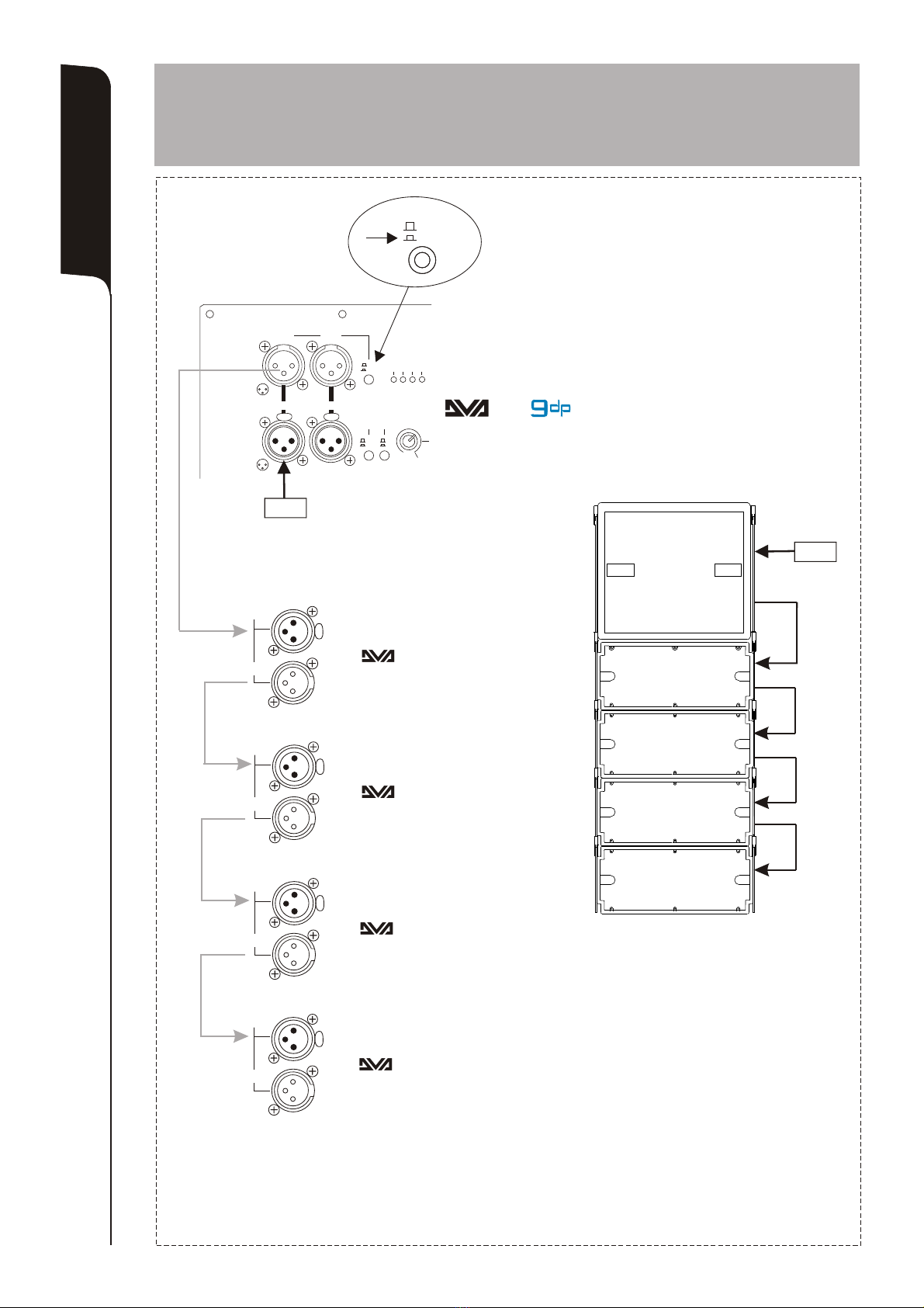
CONTROLS AND FUNCTIONS (picture ref. pag.21)
1) " BALANCED INPUT 1” AND " BALANCED INPUT 2”INPUT CONNECTORS
Balanced inputs at line level.Accept “XLR” sockets.
2) "OUT 1 ” AND "OUT 2 ” OUTPUT CONNECTORS
The “XLR” connectors be used to send the input audio signal to another amplified
speaker.
The signal is choosing between “LINK/XOVER” (10) switch.
3) “LIM” LIMITER INDICATOR LIGHT
This indicator shows red to indicate that the internal limiter starts working.
This prevents amplifier distortion and protects the speakers against overloads.
4) “SGN” SIGNAL INDICATOR LIGHT
This indicator shows green to indicate the presence of the audio signal (at a level of -
20dB).
5) “MUTE” INDICATOR LIGHT
This yellow indicator indicates amplifier status.
The LED is off in normal operating conditions.
6) “ON” READY INDICATOR LIGHT
This indicator shows green to indicate that the main power voltage is correct.
The LED shows green normal operating conditions
7) “SUBWOOFER LEVEL” INPUT SENSITIVITY CONTROL
This control adjusts the sensitivity of the signal amplifier input.
This control does not affect the "OUT 1 ” and "OUT 2 ” outputs levels
8) “PHASE” SWITCH
This two-position switch permits turning the audio signal’s phase by 180°.
Rotation makes it easier to optimise the reproduction of the low frequencies even in
the most difficult installation situations. After completing installation, play a piece of
music and move the switch to achieve the best sound reproduction at low
frequencies.
9) “XOVER” SWITCH
This switch permits selecting the crossover frequency between the
subwoofer and the speakers connected to the "OUT 1 ” and "OUT 2 ” outputs.
Choicedependson the type of speaker used for reproduction of mid-high
frequencies.
For speakers with 12” cones, it is best to use 120Hz, while with 15”
speakers 90Hz.
10) "LINK/XOVER" SWITCH
This switch allows to select the signal type to send "OUT 1 ” and "OUT 2 ” outputs.
The “LINK” position allows to link the same input signal.
The “XOVER” position allows to send input signal according to crossover frequency
select by XOVER (9) switch.
11) "MAINS INPUT" POWER SOCKET
For connecting the power cable provided.
The connector used for mains connection is a POWER CON® (blue) socket.
12) “MAINS LINK” POWER SOCKETS
For linking the mains power.The outputs are connected in parallel with input (11) and
can be used to power other active speakers.
The connectors are POWER CON® (grey) sockets.
13) "MAINS FUSE" FUSE CARRIER
Mains fuse housing.
14) COOLING GRILLE
These grilles permit cooling the amplifier during operation.
Do not block accesses and clean the grilles whenever necessary to ensure correct
air circulation.
TECHNICAL SPECIFICATIONS
System Active
®
Type of amplifier Class D (DIGIPRO )
RMS power 1000W
Music power 2000W
Frequency response 40-120Hz (-3dB)
38Hz - XOVER (-10dB)
Crossover 90Hz - 120Hz selectable 24dB/oct
Sound pressure (max SPL) 135dB
Woofer 1x15” neodymium - 4” voice coil
Input sensitivity max -3dBu
Impedance input Balanced 20Kohm
Unbalanced 10Kohm
Power supply Full-range with PFC, 100-240Vac, 50-60Hz
Housing shape Rectangular
Colour Black
Dimension (WxHxD) 515x440x720mm
Weight 37,5Kg
Weight (with brackets) 41,5 Kg
Pole mount cup M20 (aluminium)
Handle 4 metal (2 per side)
CHARACTERISTICS
Cooling
The amplifier is cooled by means of the aluminium panel placed on the back of the speaker.
The thermal protection is ensured by an internal circuit which controls the temperature of
the amplifier and protects this against any risk of overheating thus limiting in proportion the
general volume ( temperature >70°C).
If the temperature reaches the maximum operating temperature (>80°C), the audio signal
is set to the “MUTE” position and it will be indicated by the switching on of the yellow
“MUTE” LED.
The requiriered volume and all functions will be restored automatically when the normal
operating temperatures are reached.
Protections
When the yellow “MUTE” LED turns on, it means that a malfunction has been detected on
the speaker, thus setting this to the mute position.
Perform the checks listed below:
- Check if the speaker is properly connected to the power supply.
- Make sure that the power supply is of correct voltage.
- Check that the amplifier is not overheated.
- Disconnect the speaker from the mains power supply, wait for a few minutes and
connect it again.
If after these tests the yellow “MUTE” LED is still on, please contact an authorised service
centre.
EMI CLASSIFICATION
According to the standards EN 55103 this equipment is designed and suitable to operate in E4
Electromagnetic environment.