Operating and Maintenance Instructions
EN
LB.5WR – LC.25WR – LB.40WR – LB.60WR – LC.105WR
8 0203 – 01/01/2011 – R.0 www.dvp.it
1
INDEX
1 INTRODUCTION....................................................................................................................................................2
1.1 GENERAL
INFORMATION .............................................................................................................................................. 2
1.2 MANUFACTURER
INFORMATION ................................................................................................................................. 2
1.3 METHOD
OF
CONSULTATION ....................................................................................................................................... 2
1.4 PERSONNEL
QUALIFICATIONS .................................................................................................................................... 2
1.5 PERSONAL
PROTECTION
EQUIPMENT ....................................................................................................................... 2
1.6 INFORMATION
PLATE.................................................................................................................................................... 3
2 SAFETY .................................................................................................................................................................3
2.1 GENERAL
WARNINGS ................................................................................................................................................... 3
2.2 RESIDUAL
RISKS ........................................................................................................................................................... 3
2.3 PICTOGRAMS................................................................................................................................................................. 4
3 PUMP DESCRIPTION ...........................................................................................................................................4
3.1 INTENTED
USE
AND
CONTRAINDICATIONS................................................................................................................ 4
3.1.1 INTENTED USE ....................................................................................................................................................... 4
3.1.2 CONTRAINDICATIONS............................................................................................................................................ 4
3.2 FKM
VERSION ................................................................................................................................................................ 4
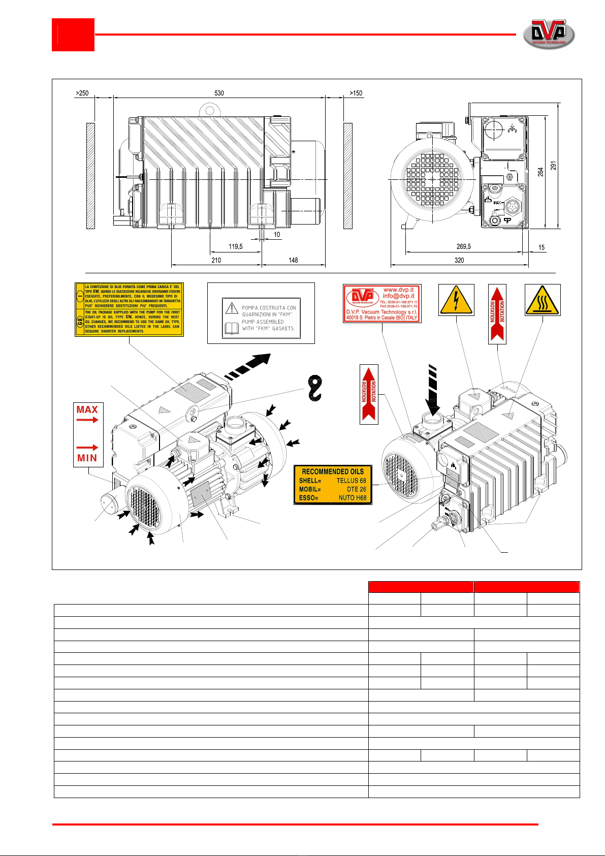
3.3 DIMENSIONS
AND
CHARACTERISTICS........................................................................................................................ 5
3.3.1 Mod l: LB.5WR ....................................................................................................................................................... 5
3.3.2 Mod l: LC.25WR ..................................................................................................................................................... 6
3.3.3 Mod l: LB.40WR – LB.60WR.................................................................................................................................. 7
3.3.4 Mod l: LC.105WR ................................................................................................................................................... 8
3.4 NOISE
EMISSION ........................................................................................................................................................... 9
4 INSTALLATION .....................................................................................................................................................9
4.1 RECEIPT
AND
CONTENT
VERIFICATION ..................................................................................................................... 9
4.2 PACKAGING.................................................................................................................................................................... 9
4.3 TRANSPORT
AND
HANDLING ....................................................................................................................................... 9
4.4 STORAGE ....................................................................................................................................................................... 9
4.5 ENVIRONMENTAL
CONDITIONS ................................................................................................................................... 9
4.6 PUMP
INSTALLATION .................................................................................................................................................. 10
4.7 MOTOR
INSTALLATION
(ONLY
LC.105WR) ................................................................................................................ 10
4.8 USER
SYSTEM.............................................................................................................................................................. 10
4.9 CONNECTION............................................................................................................................................................... 10
4.9.1 ASSEMBLING THE INTAKE FILTER (ONLY LB.5WR).......................................................................................... 10
4.9.2 INTAKE AND OUTLET CONNECTIONS................................................................................................................ 10
4.9.3 WIRING .................................................................................................................................................................. 11
4.9.4 ELECTRICAL OIL LEVEL GAUGE......................................................................................................................... 11
5 OPERATING INSTRUCTIONS............................................................................................................................12
5.1 OPERATION.................................................................................................................................................................. 12
5.1.1 FILLING THE OIL TANK......................................................................................................................................... 12
5.1.2 START-UP.............................................................................................................................................................. 12
5.1.3 PUMPING WATER VAPOUR................................................................................................................................. 12
5.1.4 INTAKE FILTER (ONLY LB.5WR).......................................................................................................................... 12
5.1.5 STOP...................................................................................................................................................................... 13
6 MAINTENANCE...................................................................................................................................................13
6.1 GENERAL
WARNINGS ................................................................................................................................................. 13
6.2 MAINTENANCE
TABLE................................................................................................................................................. 13
6.2.1 CHECK THE OIL LEVEL AND THE ABSENCE OF WATER VAPOUR CONDENSED IN THE TANK .................. 14
6.2.2 CHECK THE STATUS OF THE INTAKE FILTER (ONLY LB.5WR) ....................................................................... 14
6.2.3 CHANGE OIL.......................................................................................................................................................... 14
6.2.4 INTAKE FILTER CARTRIDGE REPLACEMENT (ONLY LB.5WR) ........................................................................ 14
6.2.5 CLEAN MOTOR FAN GUARD AND CLEAN THE PUMP....................................................................................... 14
6.2.6 CHANGE THE AIR EXHAUST FILTER .................................................................................................................. 14
6.2.7 CHANGE VANES ................................................................................................................................................... 14
6.3 SPARE
PARTS .............................................................................................................................................................. 15
7 HOW TO RETURN THE PUMP...........................................................................................................................15
8 DISMANTLING ....................................................................................................................................................15
9 TROU LESHOOTING.........................................................................................................................................16