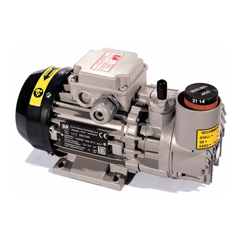
DVP MA.15 User manual

MUM- 49A ( I ) 17/11/03-R.2
MANUALE D'USO E MANUTENZIONE
POMPE PER VUOTO A MEMBRANA
MA.15 MA.15S MV.15S MA.30P MV.30P
MA.15
230V 50-60Hz 12-24V cc
MA.15S
220-240V 50-60Hz 12-24V cc
MV.15S - MV.30P MA30.P
220-240V 50-60Hz 220-240V 50-60Hz 12-24V cc
1ASPIRAZIONE 5VENTOLA RAFFREDDAMENTO
2SCARICO 6ALIMENTAZIONE
3CONDENSATORE 7TARGHETTA MOTORE
4TARGHETTA IDENTIFICAZIONE

MUM-49A MA.15-MA.15S-MV.15S-MA.30P-MV.30P 17/11/03-R.2
Pag.2D.V.P. Vacuum Technology S.r.l.
MODELLO MA.15 (MV.15S) MA.15S (MV.30P) MA.30P
Volt V230 12 24 230 12 24 230 12 24
Frequenza Hz 50 60 cc cc 50 60 cc cc 50 60 cc cc
Portata nominale nl/min 15 18 15 15 18 15 30 33 30
Pressione finale (Ass.) mbar (hPa) 100 15 80
Potenza motore W95* 15
(140*) 45
30
(140*) 45
30
Rumorosità dB(A) 50 52 50 52 53 52 53
Peso kg 1,8 1,2 (2,9) 3,7 1,8 (2,9) 3,9 2
Temp. di funz.(temp. ambiente 20°C) °C - - - - - - 40 42 40 45 50÷55
(40)30 (45)35
55 50
Temp. ambiente di lavoro richiesta. °C 0÷40
Temp. amb. di immagazz./trasporto °C 0÷40
Attacco aspirazione "G 1/8
Fattore di servizio S3 25% S1 S1 S1
(*) Potenza assorbita.
1 INTRODUZIONE
1.1 Scopo del manuale.
Questo manuale illustra le corrette procedure
per il disimballo, l’installazione l'uso, la
manutenzione, l'immagazzinamento e la
rottamazione delle pompe serie MA. Prima di
iniziare ad operare leggete attentamente le
istruzioni contenute in questo manuale. Nel
manuale sono impiegate due simbologie:
La prima si riferisce a istruzioni che se
disattese possono provocare danni alla pompa.
La seconda si riferisce a istruzioni che
se disattese possono creare condizioni
di pericolo per l'operatore. Tutte le
unità di misura utilizzate nel presente manuale
sono conformi al sistema SI. Le caratteristiche
dei prodotti possono variare senza preavviso.
2 INSTALLAZIONE
2.1 Disimballo.
Controllate che l'imballo non sia danneggiato,
in caso contrario controllate che la pompa
funzioni correttamente. In caso di danni inviate
reclamo scritto al trasportatore indicando
anche il numero di bolla, data e notificate
l'inconveniente al venditore.
Aprite la scatola e rimuovete gli eventuali
residui di materiale di imballaggio dalla pompa.
Nel caso in cui la pompa non venga utilizzata
immediatamente riponetela nuovamente
nell'imballo in un ambiente secondo le
condizioni indicate in tabella (dati tecnici)
2.2 Sistema utilizzatore.
Assicuratevi che il sistema utilizzatore non sia
contaminato da sostanze nocive durante le
operazioni di installazione.
Montate una valvola di isolamento fra
pompa e sistema se desiderate che questo
rimanga in vuoto anche a pompa ferma.
Assicuratevi che non vengano trasmesse
vibrazioni o carichi sull'attacco della pompa.
2.3 Alloggiamento.
Per assicurare il perfetto
funzionamento è necessario che
questa venga alloggiata in vani
aerati in posizione orizzontale ed in modo che
durante il funzionamento non sia
direttamente raggiungibile da qualsiasi parte
del corpo.
Si deve evitare assolutamente che l'aria calda
ristagni all'interno di suddetto vano. Non
collocate nessun elemento vicino alla ventola di
raffreddamento del motore in modo che
impedisca il normale afflusso dell'aria.
La pompa è dotata di piedini di fissaggio,
provvedere, quindi, al fissaggio della stessa per
evitare pericoli di ribaltamento in caso di
trasporto del sistema.
2.4 Collegamento elettrico.
Il collegamento elettrico deve essere
effettuato da personale qualificato
rispettando le normative elettriche
vigenti.

17/11/03-R.2 MA.15-MA.15S-MV.15S-MA.30P-MV.30P MUM-49A
D.V.P. Vacuum Technology S.r.l. pag.3
Controllate che la tensione di
alimentazione corrisponda a quella indicata
sulla targhetta del motore. La pompa è dotata
di un interruttore termico automatico (solo per
versioni con tensione alternata). Installate
sempre un sistema di protezione elettrica tra la
pompa e la rete di alimentazione. Troverete i
valori di assorbimento sulla targhetta del
motore.
2.5 Connessioni aspirazione e scarico.
Non utilizzate tubazioni rigide per la
connessione dell'aspirazione e dello scarico.
Non è possibile utilizzare la pompa come
compressore. Utilizzate sempre un filtro in
aspirazione in particolare se la pompa
lavora con flussi non puliti.
La pompa è dotata di un raccordo
all'aspirazione di tipo filettato.
L'accoppiamento con l'utilizzo quindi deve
essere realizzato con raccordi della stessa
dimensione. Evitare comunque: diametri troppo
piccoli (mai minori del diametro di aspirazione
della pompa); lunghezze eccessive, curve strette
e frequenti.
3 USO
3.1 Flussi aspirabili.
La pompa è stata progettata e costruita in
tecnopolimero PPS e con valvole e membrane
in VITON o EPDM, quindi possono aspirare
anche gas aggressivi , sempre con temperature
comprese tra 0 e 40°C, comunque compatibili
con i materiali di costruzione della pompa.
3.2 Procedura di avviamento.
Assicuratevi che lo scarico della
pompa non sia ostruito.
La pompa può raggiungere
temperature elevate durante il
funzionamento. Dopo l'accensione della pompa
questa può funzionare a un regime di rotazione
inferiore a quello normale. Se il regime di
rotazione non raggiunge il valore nominale in
pochi secondi deve scattare l'interruttore
termico installato a protezione della pompa
(solo per versioni a corrente alternata) .
3.3 Spegnimento.
Prima di spegnere la pompa per lunghi periodi
raccomandiamo di farla funzionare con
l'aspirazione aperta per circa 10 minuti. Questa
operazione permette di smaltire l'eventuale
umidità presente nella camera di aspirazione.
4 MANUTENZIONE
4.1 Informazioni generali.
Seguite attentamente le istruzioni,
in caso contrario si potrebbero
verificare situazioni pericolose per
l'operatore e la pompa.
Isolate sempre la pompa dalla rete elettrica in
modo che non possa avviarsi accidentalmente.
Non operate sulla pompa fino a quando
questa non ha raggiunto una temperatura
non pericolosa per l'operatore.
Assicuratevi che l'operatore sia
tecnicamente preparato ad operare su
pompe per vuoto e che segua tutte le
norme nazionali riguardanti gli strumenti
di protezione individuali.
4.2 Individuazione dei guasti.
Qualora la pompa non funzioni correttamente
controllate anzitutto che il problema lamentato
non venga risolto da una delle situazioni
riportate nella tabella alla pagina seguente.
Se il problema non venisse risolto contattate il
servizio assistenza.
4.3 Sono disponibili per ogni pompa i kit di
manutenzione con relative specifiche.
5 RITORNO DELLA POMPA
E' importante riportare sempre il codice, il
numero di lotto di produzione e la data di
acquisto della pompa in ogni comunicazione
con il fornitore. La pompa in ogni caso non
può essere resa senza precedenti accordi con il
fornitore.
E' necessario in caso di riparazione dichiarare
oltre ai dati sopracitati anche l'esatta anomalia
riscontrata e le sostanze che sono venute a
contatto con la pompa e i rischi che la
manipolazione della pompa può comportare.

MUM-49A MA.15-MA.15S-MV.15S-MA.30P-MV.30P 17/11/03-R.2
Pag.4D.V.P. Vacuum Technology S.r.l.
Difetto Causa Rimedio
1Alimentazione motore non corretta 1.1 Controllare la tensione di
alimentazione.
2Interruttore termico scattato (solo per
versioni con tensione alternate).
2.1 Verificare le cause che lo hanno
generato.
3Aspirazione sostanze non consentite. 3.1 Rivolgersi al servizio assistenza.
A. La pompa non
funziona
4Avvolgimento motore rotto. 4.1 Rivolgersi al servizio assistenza.
1Alimentazione motore non corretta.1.1 Controllare la tensione alimentazione
2Scarico ostruito. 2.1 Controllare i tubi allo scarico.
B. La pompa non
raggiunge il
vuoto
dichiarato.
3Guarnizioni deteriorate 3.1 Sostituire Guarnizioni
1Guarnizioni deteriorate. 1.1 Sostituire Guarnizioni
2Cuscinetti motore danneggiati. 2.1 Rivolgersi al servizio assistenza.
3Scarico ostruito. 3.1 Controllare i tubi allo scarico.
C. La pompa è
rumorosa.
4Vibrazioni trasmesse all’utilizzatore 4.1 Montare antivibranti .
1Insufficiente ventilazione ambientale 1.1 Installare un ventilatore ausiliario.
2Ventola motore rotta. 2.1 Rivolgersi al servizio assistenza.
3Alimentazione motore non corretta. 3.1 Rivolgersi al servizio assistenza.
D. Temperatura
pompa elevata.
4Superamento del fattore di servizio Vedere tabella
DICHIARAZIONE DEL FABBRICANTE
La società sotto indicata:
D.V.P. Vacuum Technology S.r.l. Via Vinca 5
40016 SAN GIORGIO DI PIANO (BO) ITALY
nella persona del suo Legale rappresentate
Mario Zucchini (Presidente)
VIETA
la messa in servizio delle pompe per vuoto
a membrana tipo:
MA.15
9215001 - 9215002
MV.15S
92016607 – 9216008
MV.30P
9217007 – 9217008
prima che le macchine in cui saranno incorporate
siano dichiarate conformi alle disposizioni delle
direttive 98/37/CEE, 73/23/CEE, 89/336/CEE e
successive modificazioni già in vigore.
Data e luogo
17/11/03 San Giorgio di Piano
Mario Zucchini
DICHIARAZIONE CE DI CONFORMITA’
La società sotto indicata:
D.V.P. Vacuum Technology S.r.l. Via Vinca 5
40016 SAN GIORGIO DI PIANO (BO) ITALY
dichiara sotto la propria esclusiva responsabilità
che le pompe per vuoto a membrana:
MA.15
9215003 – 9215004 – 9215005 - 9215006
MA.15S
9216001 – 9216002 - 9216003
9216004 – 9216005 - 9216006
MA.30P
9217001 – 9217002 - 9217003
9217004 – 9217005 - 9217006
Alle quali questa dichiarazione si riferisce,
sono Conformi:
Ai requisiti delle normative 98/37/CEE,
89/336/CEE, 72/73/CEE e successive modifiche
già in vigore alla data odierna.
Data e luogo
17/11/03 San Giorgio di Piano
Mario Zucchini
D.V.P. Vacuum Technology S.r.l.
Via Vinca 5, 40016 S. Giorgio di Piano 40016 (BO) ITALY
Tel (051) 665.00.20 Fax (051) 665.04.16
http://www.dvp.it; e-mail: info@dvp.it


MUM- 49A ( GB ) 17/11/03-R.2
USE AND MAINTENANCE MANUAL
DIAPHRAGM VACUUM PUMPS
MA.15 MA.15S MV.15S MA.30P MV.30P
MA.15
230V 50-60Hz 12-24V cc
MA.15S
220-240V 50-60Hz 12-24V cc
MV.15S - MV.30P MA30.P
220-240V 50-60Hz 220-240V 50-60Hz 12-24V cc
1 INLET 5 COOLING FAN
2OUTLET 6POWER SUPPLY SOCKET
3CAPACITOR 7MOTOR PLATE
4 ID PLATE

MUM-49A MA.15-MA.15S-MV.15S-MA.30P-MV.30P 17/11/03-R.2
D.V.P. Vacuum Technology S.r.l. Pag.2
MODEL MA.15 (MV.15S) MA.15S (MV.30P) MA.30P
Volt V230 12 24 230 12 24 230 12 24
Frequecy Hz 50 60 cc cc 50 60 cc cc 50 60 cc cc
Nominale flow rate nl/min 15 18 15 15 18 15 30 33 30
Final pressure (Asb.) mbar (hPa) 100 15 80
Motor power W95* 15
(140*) 45
30
(140*) 45
30
Noise level dB(A) 50 52 50 52 53 52 53
Weight kg 1,8 1,2 (2,9) 3,7 1,8 (2,9) 3,9 2
Operat. temp.(ambient temp 20°C) °C - - - - - - 40 42 40 45 50÷55
(40)30 (45)35
55 50
Req. room temp for installation °C 0÷40
Ambient temp. for storage/transport °C 0÷40
Inlet connection "G 1/8
Service factor S3 25% S1 S1 S1
(*) Required power.
1 INTRODUCTION
1.1 purpose of the manual.
This manual illustrates the correct procedures
for unpacking, installing, use, maintenance,
store and dispose pumps MA series. Before
beginning to operate you have to attentively
read the instructions contained in this manual.
In the manual two simbologies are employed:
The first refers to instructions that if not
followed can cause damages to the pump.
The second refers to instructions that
if followed can generate damages to
the pump.
All the measuring units used in the present
manual are in conformity to the International
System. The characteristics of the products can
vary without prior notice.
2 INSTALLATION
2.1 Unpack.
Check that the pack is not damaged, on the
contrary check that the pump operates
correctly. In case of damages, please send
claim in writing to the carrier, also pointing
out the delivery note number, date and notify
the seller.
Open the pack and remove the possible residues
of material of packing from the pump. Should
the pump is not immediately installed, pack it
again and store accordingly to the table.
2.2 User system.
Make sure that the user system is not
contaminated from harmful substances during
the operations of installation.
Install an isolation valve between pump
and system if you desire that it remains under
vacuum also when the pump is not operating.
Make sure that vibrations or tensions are not
transmitted to the connections of the pump.
2.3 Positioning.
To assure the perfect operation it is
necessary that the pump is installed
in a well ventilated room in
horizontal position and that during the
operations it is not attainable from any part
of the body.
It is absolutely necessary to avoid that the warm
air remain inside the installation vane. Do not
put any elements near the cooling fan of the
motor that alter the normal airflow.
The pump is supplied with fixing points,
therefore, it must be fixed on the user system to
avoid dangers in case of case turnover during
transport.
2.4 Electric connection.
The electric connection must be
performed by trained personnel in
compliance with local electrical
standard in force.

17/11/03-R.2 MA.15-MA.15S-MV.15S-MA.30P-MV.30P MUM-49A
D.V.P. Vacuum Technology S.r.l. Pag.3
Make sure that the supply voltage
matches that on the motor rating plate.
The pump is equipped with an automatic
thermal circuit breaker (only for versions with
AC motor).
An electric protection system should
always be provided between pump and
mains. Electrical input values are stated on
the motor rating plate.
2.5 Inlet and outlet connection.
Do not use rigid pipes to connect intake
and outlet.
It is not possible to use the pump as
compressor.
Always install an intake filter, especially if
the pump is working with fluids that might
contain foreign matters.
The pump is supplied with threaded inlet/outlet
connections. So it is necessary to connected the
system using the same threads. Never use small
bore hose (smaller than the pump inlet
diameter). Avoid excessive hose lengths, tight
bends or bends spaced too closely.
3 USE
3.1 Allowable intake media.
The pump has been designed and built using
PPS plastic and with VITON or EPDM valves
and membranes, therefore you can also operate
with aggressive gases, always with
temperatures between 0 and 40°C, however
compatible with the materials of construction
of the pump.
3.2 Start-up.
Make sure that pump exhaust is
not obstructed by either its
connecting hose or fittings.
The pump may reach high
temperatures when operating
After start-up, the pump may run slower than
regular r.p.m. if ambient temperature is lower
than that permitted. If nominal r.p.m. is not
reached within a few seconds, the thermal
switch fitted to protect the pump will trip (only
for AC motor).
3.3 Power off.
Before the pump is switched off, let it run with
open intake for about 10 minutes. This
operation allows to dry the possible traces or
moisture in the suction chamber.
4 MAINTENANCE
4.1 General information.
Follow the instructions carefully, otherwise
hazards may arise for the operator and the
pump may be damaged.
Before any service is carried out always
disconnect pump from mains to prevent
unintentional starting.
Do not service the pump when it is so hot as
to endanger operator's safety.
Make sure that operator is specifically
trained for operating vacuum pumps and
observes all rules in force regarding
personal safety and protective equipment.
4.2 Troubleshooting.
If the pump malfunctions, try the following
measures first to eliminate the problem.
If trouble persists, contact Service Department.
5 RETURN OF THE PUMP
Pump type, serial number and purchase date
should always be stated in all correspondence
with the supplier.
The pump may only be returned after prior
agreement with the supplier.
Should the pump need service, the above
information should be given, with an accurate
description of the faults, what substances have
been in contact with the pump, and which
hazards are involved in handling the pump.

MUM-49A MA.15-MA.15S-MV.15S-MA.30P-MV.30P 17/11/03-R.2
Pag.4D.V.P. Vacuum Technology S.r.l.
Defect Cause Remedy
1 Power supply is not correct 1.1 Check the tension.
2 Thermal switch tripped (only for versions
with alternated tension).
2.1 Verify the causes that have
produced it.
3 Operation with not allowed substances. 3.1 Call service.
A. Pumps doesn't
operate
4 Motor winding fault. 4.1 Call service.
1 Power supply is not correct 1.1 Check the tension.
2 Outlet obstructed. 2.1 Check the pipes.
B. The pump
doesn't reach
the declared
pressure. 3 Gaskets deterioration 3.1 Replace Gaskets
1 Gaskets deterioration 1.1 Replace Gaskets
2 Motor bearings damaged. 2.1 Call service.
3 Outlet obstructed. 3.1 Check the pipes.
C. The pumps is
noisy.
4 Vibrations transmitted to the pump
from the system
4.1 Install shock mounts
1 Insufficient environmental ventilation 1.1 Install an auxiliary fan.
2 FAN motor rout. 2.1 Call service.
3 Power supply is not correct 3.1 Call service.
D. High pump
temperatur.
4 Overcoming of the service factor 4.1 See table
DECLARATION OF THE MANUFACTURER
The society:
D.V.P. Vacuum Technology S.r.l. Via Vinca 5
40016 SAN GIORGIO DI PIANO (BO) ITALY
in the person of his President
Mario Zucchini
FORBID
the operation of the diaphragm
vacuum pumps type:
MA.15
9215001 – 9215002
MA.15S
9216007 – 9216008
MV.30P
9217007 – 9217008
before the machine in which they will be
incorporated will be declared compliant
with the dispositions of the
directives 98/37/CEE, 73/23/CEE, 89/336/CEE
and following modifications.
Date and place
19/05/03 S. Giorgio di Piano
Mario Zucchini
CE DECLARATION OF CONFORMITY'
The society:
D.V.P. Vacuum Technology S.r.l. Via Vinca 5
40016 SAN GIORGIO DI PIANO (BO) ITALY
it declares under its sole exclusive responsibility
that the vacuum
diaphragm pumps types:
MA 15
9215003 – 9215004 – 9215005 - 9215006
MA 15S
9216001 – 9216002 – 9216003
9216004 – 9216005 - 9216006
MA 30P
9217001 – 9217002 – 9217003
9217004 – 9217005 - 9217006
to which this declaration refers comply with:
directives 98/37/CEE, 73/23/CEE, 89/336/CEE and
following modifications
Date and place
19/05/03 S. Giorgio di Piano
Mario Zucchini
D.V.P. Vacuum Technology S.r.l.
Via Vinca 5, 40016 S. Giorgio di Piano 40016 (BO) ITALY
Tel (051) 665.00.20 Fax (051) 665.04.16
This manual suits for next models
26
Table of contents
Languages:
Other DVP Water Pump manuals
Popular Water Pump manuals by other brands

Vivaria
Vivaria VarioTec N-4500 operating instructions

Becker
Becker SH 19 Additional instructions

ITT Industries
ITT Industries Goulds Pumps 3656 Installation, operation and maintenance instructions

Gasboy
Gasboy 9820 installation instructions

Armstrong
Armstrong 4200H Installation and operating instructions

Neptun
Neptun NSP 60i operating instructions

Becker
Becker SV 500 operating instructions

EINHELL
EINHELL GC-DP 9035 N Original operating instructions

IWAKI PUMPS
IWAKI PUMPS EJ-B instruction manual

Pentair
Pentair Flotec OMNIA 80/5 Use and maintenance manual

Legend
Legend ECO-TOUCH VS Installation and operation manual

masosine
masosine Certa 100 user manual