DVP LC.2 Manual

VACUUM
TECHNOLOGY
OPERATING AND MAINT ENANCE
INSTRUCTIONS
(Translation of the original instructions)
ACUUM PUMPS WITH RECIRCULATING
LUBRICATION SYSTEM
LC
.2
LC.4
LB.5
LB.6
LB.8
LC.12
LC.20

Operating and Maintenance Instructions EN
LC.2 – LC.4 – LB.5 – LB.6 – LB.8 – LC.12 – LC.20
1
8702036 – 12 04 2016 – R.7 www.dvp.it
INDEX
1 INTRODUCTION .................................................................................................................................................... 2
1.1 GENERAL INFORMATION .............................................................................................................................. 2
1.2 MANUFACTURER INFORMATION ................................................................................................................. 2
1.3 METHOD OF CONSULTATION ...................................................................................................................... 2
1.4 PERSONNEL QUALIFICATIONS .................................................................................................................... 2
1.5 PERSONAL PROTECTION EQUIPMENT....................................................................................................... 2
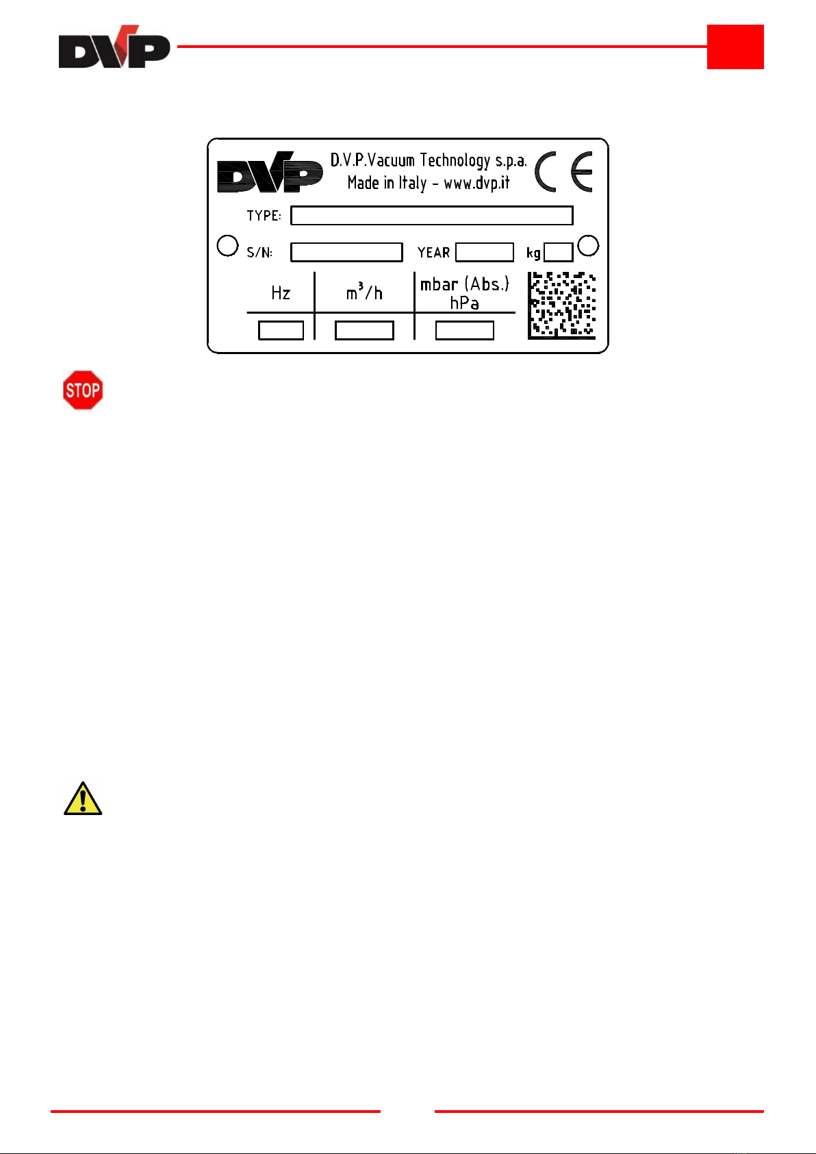
1.6 INFORMATION PLATE ................................................................................................................................... 3
2 SAFETY ................................................................................................................................................................. 3
2.1 GENERAL WARNINGS ................................................................................................................................... 3
2.2 RESIDUAL RISKS ........................................................................................................................................... 3
2.3 PICTOGRAMS ................................................................................................................................................. 4
3 PUMP DESCRIPTION ........................................................................................................................................... 5
3.1 INTENTED USE AND CONTRAINDICATIONS ............................................................................................... 5
3.1.1 INTENTED USE ........................................................................................................................................ 5
3.1.2 CONTRAINDICATIONS ............................................................................................................................ 5
3.2 FKM VERSION ................................................................................................................................................ 5
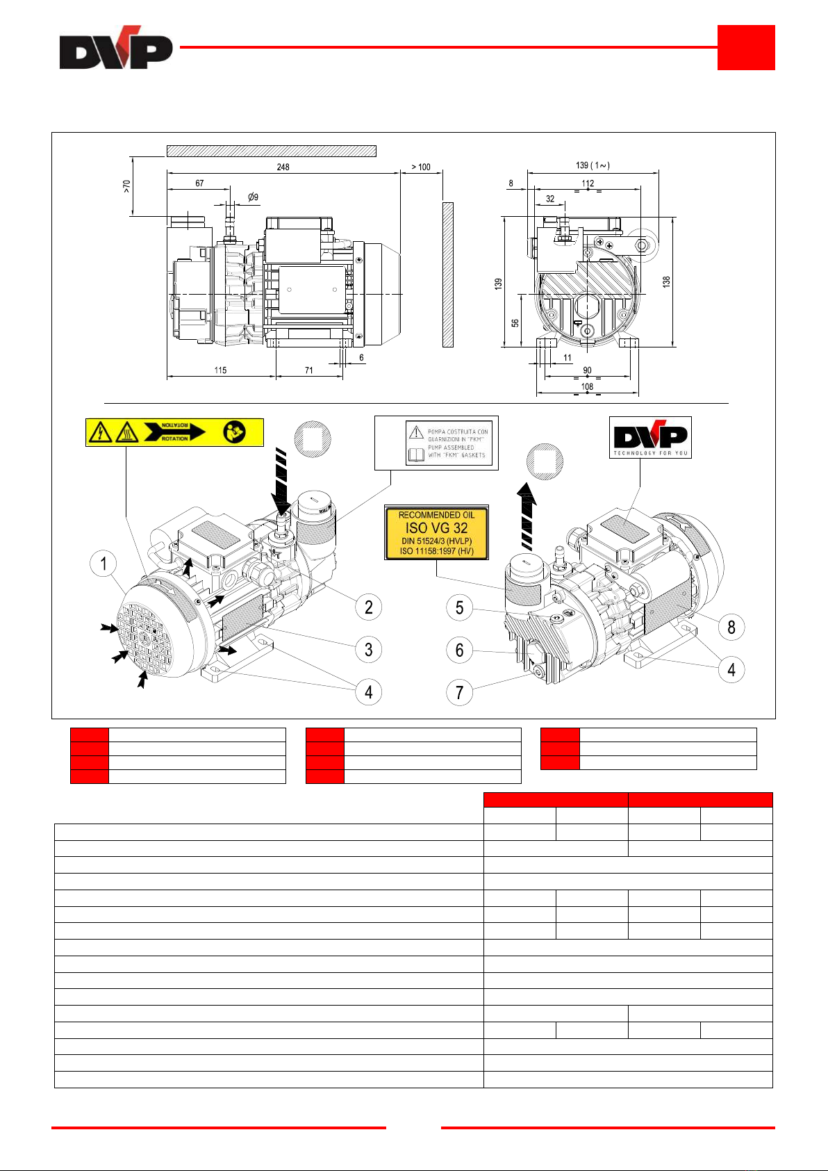
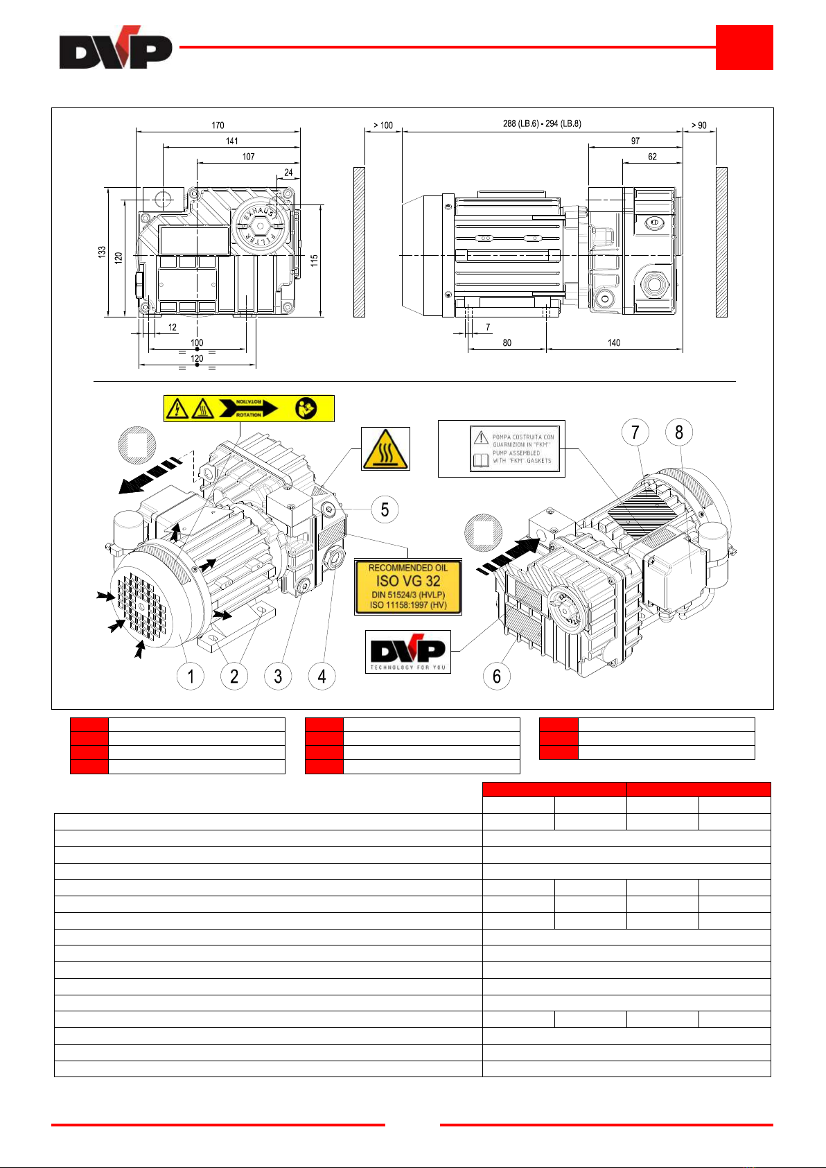
3.3 DIMENSIONS AND CHARACTERISTICS ....................................................................................................... 6
3.3.1 Mod l: LC.2 – LC.4................................................................................................................................... 6
3.3.2 Mod l: LB.5 .............................................................................................................................................. 7
3.3.3 Mod l: LB.6 – LB.8 ................................................................................................................................... 8
3.3.4 Mod l: LC.12 ............................................................................................................................................ 9
3.3.5 Mod l: LC.20 .......................................................................................................................................... 10
3.4 NOISE EMISSION ......................................................................................................................................... 11
4 INSTALLATION ................................................................................................................................................... 11
4.1 RECEIPT AND CONTENT VERIFICATION .................................................................................................. 11
4.2 PACKAGING .................................................................................................................................................. 11
4.3 TRANSPORT AND HANDLING ..................................................................................................................... 11
4.4 STORAGE ..................................................................................................................................................... 11
4.5 ENVIRONMENTAL CONDITIONS ................................................................................................................ 12
4.6 PUMP INSTALLATION .................................................................................................................................. 12
4.7 USER SYSTEM ............................................................................................................................................. 12
4.8 CONNECTION ............................................................................................................................................... 12
4.8.1 INTAKE AND OUTLET CONNECTIONS ................................................................................................ 12
4.8.2 WIRING ................................................................................................................................................... 13
5 OPERATING INSTRUCTIONS ............................................................................................................................ 14
5.1 OPERATION .................................................................................................................................................. 14
5.1.1 FILLING THE OIL TANK ......................................................................................................................... 14
5.1.2 START-UP .............................................................................................................................................. 14
5.1.3 STOP ....................................................................................................................................................... 14
5.1.4 PUMPING WATER VAPOUR ................................................................................................................. 14
6 MAINTENANCE ................................................................................................................................................... 15
6.1 GENERAL WARNINGS ................................................................................................................................. 15
6.2 MAINTENANCE TABLE................................................................................................................................. 15
6.2.1 CHECK OIL LEVEL ................................................................................................................................. 15
6.2.2 CHANGE OIL .......................................................................................................................................... 15
6.2.3 CLEAN MOTOR FAN GUARD EAND CLEAN THE PUMP .................................................................... 16
6.2.4 CHANGE THE AIR EXHAUST FILTER .................................................................................................. 16
6.2.5 CHANGE VANES .................................................................................................................................... 16
6.3 SPARE PARTS .............................................................................................................................................. 16
7 HOW TO RETURN THE PUMP ........................................................................................................................... 17
8 DISMANTLING .................................................................................................................................................... 17
9 TROU LESHOOTING ......................................................................................................................................... 18

Operating and Maintenance Instructions EN
LC.2 – LC.4 – LB.5 – LB.6 – LB.8 – LC.12 – LC.20
2
8702036 – 12 04 2016 – R.7 www.dvp.it
1 INTRODUCTION
1.1 GENERAL INFORMATION
This manual is m ant to provid you with important information for th saf ty of p rsons involv d in pump us and
maint nanc .
This manual, originally writt n in ITALIAN, is an int gral part of th pump and must b pr s rv d with car for th
lif of th pump its lf. In th v nt of sal , l as or loan d us of th pump, it must b d liv r d to th n w us r
along with EC d claration of conformity.
Carrying out any op rations on th pump b for r ading and fully und rstanding all instructions in this manual is
prohibit d.
Th imag s contain d in this docum nt ar xampl s only and ar not binding for th Manufactur r. Th
Manufactur r r s rv s th right to mak chang s to compon nts, product improv m nt parts and any oth r without
updating this manual, if said compon nts or parts do not alt r pump op ration and saf ty.
1.2 MANUFACTURER INFORMATION
D.V.P. Vacuum Technology s.p.a.
Via Rubizzano, 627
40018 - S. Pi tro in Casal (BO) - ITALY
Ph
+3905118897101
Fx
+3905118897170
-mail:
w b sit :
http://www.dvp.it
Pl as always includ th following information in all communications r garding th pump:
• pump mod l and s rial numb r
• y ar of manufactur
• dat of purchas
• d tail information r garding probl ms v rifi d
1.3 METHOD OF CONSULTATION
For improv d und rstanding of th information provid d in this manual, warnings or instructions consid r d critical
or hazardous ar mark d with th following symbols:
HAZARD
Failure to comply with these instructions may cause hazards to persons.
WARNING
Failure to comply with these instructions may cause damage to the pump.
1.4 PERSONNEL QUALIFICATIONS
To nsur that all op rations p rform d on th pump ar carri d out saf ly, op rators must hav th qualifications
and r quir m nts to carry out its op rations.
Op rators ar classifi d as follows:
FIRST LEVEL OPERATOR:
Unqualifi d p rsonn l, having no sp cific skills, abl to p rform simpl tasks only.
MECHANICAL MAINTENANCE OPERATOR:
T chnician qualifi d to work on m chanical parts to carry out any n c ssary adjustm nts, maint nanc
or r pairs. Not qualifi d to work on l ctrical syst ms in th pr s nc of voltag .
ELECTRICAL MAINTENANCE OPERATOR:
T chnician in charg of all op rations of an l ctrical natur . Can op rat in th pr s nc of voltag
insid cabin ts and conn ctor box s.
1.5 PERSONAL PROTECTION EQUIPMENT
This manual assum s that th pump has b n install d in workplac s, which comply with all mandatory saf ty
r quir m nts; in particular, it is mandatory that p rsonn l ar quipp d with p rsonal prot ctiv quipm nt in
r lation to th activiti s that must b p rform d.

Operating and Maintenance Instructions EN
LC.2 – LC.4 – LB.5 – LB.6 – LB.8 – LC.12 – LC.20
3
8702036 – 12 04 2016 – R.7 www.dvp.it
1.6 INFORMATION PLATE
All pumps ar quipp d with an id ntification plat that contains th manufactur r's nam , addr ss, CE marking
and t chnical data of th pump its lf.
WARNING
Removing or tampering with the identification plate is strictly prohibited.
2 SAFETY
2.1 GENERAL WARNINGS
It is important to r ad this manual b for p rforming any op ration on th pump. Complianc with th saf ty
standards of th country in which th pump is install d and r quir m nts of qualifi d p rsonn l for various
maint nanc , us , installation, tc. ar r comm nd d throughout th lif of th pump.
Th main rul s of conduct to b obs rv d for op ration at a suitabl l v l of s curity ar th following:
• Installation, op ration, maint nanc , tc. op rations should always b p rform d by qualifi d, train d p rsonn l.
• Without xc ption, always w ar n c ssary p rsonal prot ctiv quipm nt.
• Always p rform all cl aning, adjustm nt and maint nanc op rations with all pow r quipm nt cut off.
• Do not dir ct wat r j ts toward l ctrical parts, v n if th y ar prot ct d by nclosur s.
• Do not smok during work or maint nanc , sp cially wh r solv nts or flammabl mat rials ar b ing us d.
• Do not damag symbol plaqu s or pictograms on th pump. If th y should accid ntally b com damag d,
imm diat ly r plac th m with oth r id ntification plaqu s.
D.V.P. Vacuum T chnology s.p.a. disclaims any liability for damag to p rsons or prop rty r sulting from improp r
us of th pump, from tamp ring with its saf ty apparatus or failur to obs rv op rational saf ty standards.
2.2 RESIDUAL RISKS
HAZARD
This pump has been designed to minimise residual risks to personnel. We urge you, however, to
take the utmost care and attention in carrying out maintenance operations. The confidence gained
with frequent contact with the pump too often leads users to forget or underestimate risks.
High temperature hazard
Pump surfac s can xc d a t mp ratur of 70°C. Install th pump in a prot ct d ar a that is acc ssibl only by
authoris d p rsonn l and only p rform op rations wh n th pump is stopp d and cool d.
Hazard generated by low pressure
Avoid contact with pump intak attachm nt during op ration. Introduc air into th suction circuit b for any
int rv ntion. Contact with low pr ssur points can caus accid nts.
Hazard generated by pressure
Th pump tank is pr ssuris d. Do not op n and do not l av oil fill r or drain plugs op n during op ration.
Danger from the emission of harmful substances
Pump outl t air contains trac s of oil mist. Ensur compatibility with th working nvironm nt.
Faults or w aring of s als may caus oil lubricant l aks. Avoid disp rsion in soil and pollution of oth r mat rials.
Wh n v r air containing hazardous substanc s ar suck d in (i. . biological or microbiological ag nts), us
abat m nt syst ms plac d b for th vacuum pump. Us d oil must b dispos d of according to applicabl
r gulations in th country of pump us .

Operating and Maintenance Instructions EN
LC.2 – LC.4 – LB.5 – LB.6 – LB.8 – LC.12 – LC.20
4
8702036 – 12 04 2016 – R.7 www.dvp.it
Electrical hazard
El ctrical quipm nt in th pump includ s liv parts which, upon contact, can caus s rious damag to p rsons and
prop rty. Any kind of int rv ntion on th l ctrical syst m must b p rform d by qualifi d p rsonn l.
Fire hazard
Us of th pump for any us s not provid d for or prohibit d by this manual as w ll as a lack of prop r maint nanc
can caus malfunction with a risk of ov rh ating and fir .
In cas of fir , do not us wat r to xtinguish th flam s, but us dry ch mical or CO2 or oth r m ans compatibl
with th pr s nc of l ctrical quipm nt and lubricants.
Slip and fall hazards
Th “L” s ri s vacuum pumps us lubricant to op rat . A simpl maint nanc or improp r us not complying with
th instructions includ d in this manual can damag th gask ts and/or s als and caus th lubricant to spill on th
floor constituting slip and/or fall hazards for p rsonn l.
Entanglement hazard
Th r is a p rman nt imp nding hazard of ntangling or ntrapping hair and clothing in th cool r fan insid th
guard n ar th fan casing on th l ctric motor. Ti long hair up and do not w ar baggy clothing, long lac s or oth r
it ms that could g t caught up.
Part projection hazard
Install th pump in ord r to avoid thos in charg of works b ing dir ctly hit by parts or bits of parts flying through
th fan cov r casing du to th cooling fan br aking.
2.3 PICTOGRAMS
Pictographs with th warning symbols and saf ty symbols for op rators hav b n appli d to th pump. R ad
car fully and tak not of th symbols and th ir m ssag s b for using th pump.
ELECTRICAL HAZARD
The pump is near electrical connections (protected) but where accidental contact can cause
electric shock and death.
HOT SURFACE HAZARD
The pump is close to surfaces with temperatures exceeding 70°C which may lead to burns of
medium severity.
REFER TO INSTRUCTION MANUAL/ OOKLET
efore use read the instructions in the operating manual.
D.V.P. Vacuum T chnology s.p.a. disclaims any liability for damag to p rsons or prop rty du to non-complianc
with instructions indicat d in pictograms or th ir improp r pr s rvation.

Operating and Maintenance Instructions EN
LC.2 – LC.4 – LB.5 – LB.6 – LB.8 – LC.12 – LC.20
5
8702036 – 12 04 2016 – R.7 www.dvp.it
3 PUMP DESCRIPTION
3.1 INTENTED USE AND CONTRAINDICATIONS
3.1.1 INTENTED USE
Th pumps d scrib d in this manual ar oil r circulating rotary van pumps. Th s vacuum pumps hav b n
sp cifically d sign d to work with cl an air, in rt gas or small amounts of wat r vapour, having a t mp ratur
b tw n 12 and 40 °C at th intak .
Th s pumps ar suitabl to vacuat small clos d v ss ls or, in cas of som mod ls, to work continuously at
sp cific final pr ssur , as xplain d in paragraph 3.3 “Dim nsions and charact ristics “.
Any oth r us is prohibit d. Th Manufactur r is not liabl for any damag to p rsons and/or prop rty caus d by
improp r us or not allow d us of th pump.
3.1.2 CONTRAINDICATIONS
Any use other than that for which the pump was constructed is to be considered an
abnormal condition and therefore can cause damage to the pump and pose a serious
danger to the operator.
B low is a s ri s of op rations involving improp r us of th pump, which ar not p rmitt d und r any
circumstanc s.
• Do not us th pump in an xplosiv or aggr ssiv atmosph r or in an atmosph r with a high conc ntration of
dust or oily substanc s in th air and do not us th pump to pump xplosiv , flammabl or corrosiv gas s or
gas that form particl s. Using th pump in th s atmosph r s and with th s typ s of gas s can caus injury,
xplosion, fir or s rious damag to th pump.
• Do not us non-original spar parts or parts not provid d by th manufactur r.
• Do not us th unit to pump solid mat rials, ch micals, powd rs, solv nts or oth r substanc s diff ring from
thos p rmitt d Th s typ s of mat rials may damag th unit, d grad its p rformanc or r duc its lif .
• do not xpos th pump to rain, st am or xc ssiv humidity.
• Do not plac or stor n ar in th proximity of flammabl or combustibl mat rials or substanc s.
• Do not us th pump as a compr ssor.
3.2 FKM VERSION
This v rsion of th pump is quipp d with sp cial t chnical d vic s, such FKM s als that allow for us v n in th
pr s nc of som aggr ssiv gas s.
WARNING
Contact the seller to make sure that the pump is suitable for use with a given aggressive gas.

Operating and Maintenance Instructions EN
LC.2 – LC.4 – LB.5 – LB.6 – LB.8 – LC.12 – LC.20
6
8702036 – 12 04 2016 – R.7 www.dvp.it
3.3 DIMENSIONS AND CHARACTERISTICS
3.3.1 Model: LC.2 – LC.4
B
A
A Intak 3 Information plat 7 Oil drain plug
Air outl t 4 Attachm nt point 8 Motor rating plat
1 Motor fun guard 5 Oil fill r plug Only pr s nt on sp cial v rsions
2 T rminal board 6 Oil sight glass
TECHNICAL SPECIFICATIONS LC.2 LC.4
50 Hz 60 Hz 50 Hz 60 Hz
Inl t capacity m³/h
2 2,5 4 4,8
Final pr ssur (Abs.) mbar - hPa
10 2
Max inl t pr ssur for wat r vapour mbar - hPa
- - - -
Max wat r vapour pumping rat kg/h
- - - -
Motor pow r kW (1~ / 3~)
0,12 / 0,12 0,15 / 0,15 0,12 / 0,12 0,15 / 0,15
Nominal r.p.m. n/min
2800 3300 2800 3300
Nois l v l (UNI EN ISO 2151) (K 3dB) dB(A)
48 52 48 52
W ight kg (1~ / 3~)
5,4 / 5,4
Typ of oil cod. DVP
BV32 (SW40)
Oil quantity dm³
0,065
Pump Intak / Outl t
Ø9mm (1/8″G) / - - -
Continuous-duty working r ng (Abs.) mbar - hPa
500 ÷ 10 - - - -
Op rating t mp ratur (room t mp. 20°C) °C
50 ÷ 55 55 ÷ 60 50 ÷ 55 55 ÷ 60
R quir d room t mp. for plac of installation °C
12 ÷ 40
Ambi nt t mp ratur for storag /transport °C
-20 ÷ 50
MAX humidity / altitud
80% / 1000m a.s.l. *
(*) Pl as contact th Manufactur r if nvironm ntal conditions ar diff r nt from thos pr scrib d.

Operating and Maintenance Instructions EN
LC.2 – LC.4 – LB.5 – LB.6 – LB.8 – LC.12 – LC.20
7
8702036 – 12 04 2016 – R.7 www.dvp.it
3.3.2 Model: L .5
B
A
A Intak 3 Attachm nt point 7 Oil sight glass
Air outl t 4 Oil fill r plug 8 T rminal board
1 Motor rating plat 5 Information plat Only pr s nt on sp cial v rsions
2 Motor fun guard 6 Oil drain plug
TECHNICAL SPECIFICATIONS LB.5
50 Hz 60 Hz
Inl t capacity m³/h
5 6
Final pr ssur (Abs.) mbar - hPa
10
Max inl t pr ssur for wat r vapour mbar - hPa
30
Max wat r vapour pumping rat kg/h
0,11
Motor pow r kW (1~ / 3~)
0,25 / 0,37 0,25 / 0,45
Nominal r.p.m. n/min
1400 1700
Nois l v l (UNI EN ISO 2151) (K 3dB) dB(A)
58 60
W ight kg (1~ / 3~)
13,0 / 11,5
Typ of oil cod. DVP
BV68 (SW60)
Oil quantity dm³
0,20
Pump Intak / Outl t “G
3/8
Continuous-duty working r ng (Abs.) mbar - hPa
400 ÷ 10
Op rating t mp ratur (room t mp. 20°C) °C
65 ÷ 70 70 ÷ 75
R quir d room t mp. for plac of installation °C
12 ÷ 40
Ambi nt t mp ratur for storag /transport °C
-20 ÷ 50
MAX humidity / altitud
80% / 1000m a.s.l. *
(*) Pl as contact th Manufactur r if nvironm ntal conditions ar diff r nt from thos pr scrib d.

Operating and Maintenance Instructions EN
LC.2 – LC.4 – LB.5 – LB.6 – LB.8 – LC.12 – LC.20
8
8702036 – 12 04 2016 – R.7 www.dvp.it
3.3.3 Model: L .6 – L .8
A
B
A Intak 3 Oil drain plug 7 Motor rating plat
Air outl t 4 Oil sight glass 8 T rminal board
1 Motor fun guard 5 Oil fill r plug Only pr s nt on sp cial v rsions
2 Attachm nt point 6 Information plat
TECHNICAL SPECIFICATIONS LB.6 LB.8
50 Hz 60 Hz 50 Hz 60 Hz
Inl t capacity m³/h
6 7 8 9
Final pr ssur (Abs.) mbar - hPa
2
Max inl t pr ssur for wat r vapour mbar - hPa
- - - -
Max wat r vapour pumping rat kg/h
- - - -
Motor pow r kW (1~ / 3~)
0,25 / 0,25 0,30 / 0,30 0,25 / 0,25 0,30 / 0,30
Nominal r.p.m. n/min
2800 3300 2800 3300
Nois l v l (UNI EN ISO 2151) (K 3dB) dB(A)
58 60 58 60
W ight kg (1~ / 3~)
10,0 / 9,0
Typ of oil cod. DVP
BV32 (SW40)
Oil quantity dm³
0,20
Pump Intak / Outl t “G
3/8
Continuous-duty working r ng (Abs.) mbar - hPa
- - - -
Op rating t mp ratur (room t mp. 20°C) °C
65 ÷ 70 70 ÷ 75 70 ÷ 75 75 ÷ 80
R quir d room t mp. for plac of installation °C
12 ÷ 40
Ambi nt t mp ratur for storag /transport °C
-20 ÷ 50
MAX humidity / altitud
80% / 1000m a.s.l. *
(*) Pl as contact th Manufactur r if nvironm ntal conditions ar diff r nt from thos pr scrib d.

Operating and Maintenance Instructions EN
LC.2 – LC.4 – LB.5 – LB.6 – LB.8 – LC.12 – LC.20
9
8702036 – 12 04 2016 – R.7 www.dvp.it
3.3.4 Model: LC.12
B
A
A Intak 3 Oil sight glass 7 Motor rating plat
Air outl t 4 Oil fill r plug 8 Motor fun guard
1 Attachm nt point 5 Information plat Only pr s nt on sp cial v rsions
2 Oil drain plug 6 T rminal board
TECHNICAL SPECIFICATIONS LC.12
50 Hz 60 Hz
Inl t capacity m³/h
12 14
Final pr ssur (Abs.) mbar - hPa
2
Max inl t pr ssur for wat r vapour mbar - hPa
35
Max wat r vapour pumping rat kg/h
0,3
Motor pow r kW (1~ / 3~)
0,45 / 0,37 0,55 / 0,45
Nominal r.p.m. n/min
2800 3300
Nois l v l (UNI EN ISO 2151) (K 3dB) dB(A)
62 64
W ight kg (1~ / 3~)
14,0 / 12,5
Typ of oil cod. DVP
BV32 (SW40)
Oil quantity Min÷Max dm³
0,30 ÷ 0,40
Pump Intak / Outl t “G
1/2
Continuous-duty working r ng (Abs.) mbar - hPa
400 ÷ 2
Op rating t mp ratur (room t mp. 20°C) °C
60 ÷ 65 65 ÷ 70
R quir d room t mp. for plac of installation °C
12 ÷ 40
Ambi nt t mp ratur for storag /transport °C
-20 ÷ 50
MAX humidity / altitud
80% / 1000m a.s.l. *
(*) Pl as contact th Manufactur r if nvironm ntal conditions ar diff r nt from thos pr scrib d.

Operating and Maintenance Instructions EN
LC.2 – LC.4 – LB.5 – LB.6 – LB.8 – LC.12 – LC.20
10
8702036 – 12 04 2016 – R.7 www.dvp.it
3.3.5 Model: LC.20
B
A
A Intak 3 Oil sight glass 7 Motor rating plat
Air outl t 4 Oil fill r plug 8 Motor fun guard
1 T rminal board 5 Information plat Only pr s nt on sp cial v rsions
2 Oil drain plug 6 Attachm nt point
TECHNICAL SPECIFICATIONS LC.20
50 Hz 60 Hz
Inl t capacity m³/h
20 24
Final pr ssur (Abs.) mbar - hPa
2
Max inl t pr ssur for wat r vapour mbar - hPa
15
Max wat r vapour pumping rat kg/h
0,25
Motor pow r kW (1~ / 3~)
0,75 / 0,75 0,90 / 0,90
Nominal r.p.m. n/min
2800 3300
Nois l v l (UNI EN ISO 2151) (K 3dB) dB(A)
64 67
W ight kg (1~ / 3~)
19,0 / 17,0
Typ of oil cod. DVP
BV32 (SW40)
Oil quantity Min÷Max dm³
0,45 ÷ 0,50
Pump Intak / Outl t “G
1/2
Continuous-duty working r ng (Abs.) mbar - hPa
400 ÷ 2
Op rating t mp ratur (room t mp. 20°C) °C
60 ÷ 65 65 ÷ 70
R quir d room t mp. for plac of installation °C
12 ÷ 40
Ambi nt t mp ratur for storag /transport °C
-20 ÷ 50
MAX humidity / altitud
80% / 1000m a.s.l. *
(*) Pl as contact th Manufactur r if nvironm ntal conditions ar diff r nt from thos pr scrib d.

Operating and Maintenance Instructions EN
LC.2 – LC.4 – LB.5 – LB.6 – LB.8 – LC.12 – LC.20
11
8702036 – 12 04 2016 – R.7 www.dvp.it
3.4 NOISE EMISSION
This pump has b n d sign d and construct d to r duc nois at its sourc .
Th sound pr ssur l v ls contain d in th tabl of t chnical sp cifications w r m asur d at maximum vacuum
and outl t conv y d according to UNI EN 2151.
4 INSTALLATION
4.1 RECEIPT AND CONTENT VERIFICATION
Upon r c ipt of th pump, v rify that th packaging is intact. If v rything is intact, unpack th cont nts and ch ck
th pump. If packaging shows signs of damag du to transport or storag conditions, imm diat ly notify th
shipping ag nt and th manufactur r.
It is always n c ssary to ch ck that th mat rial r c iv d corr sponds to its accompanying docum nt.
Packag s should b op n d taking all pr cautions to avoid harm to p opl and th cont nts th r of.
4.2 PACKAGING
D p nding on th siz and bas d on th mod of transport, th pump is packag d in th following ways:
• singl box with infill mat rial;
• on wood n pall ts with cardboard cov rs;
• in singl box s position d on pall ts with prot ctiv film.
Th pall t wood can b r us d or r cycl d in accordanc with applicabl laws in th country of pump installation.
Oth r mat rials such as cardboard, plastic or prot ctiv film must b dispos d of in accordanc with local
r gulations.
Do not burn or disp rs packag compon nts in th nvironm nt.
4.3 TRANSPORT AND HANDLING
HAZARD
All transportation, lifting and handling operation must be performed by qualified and experienced
personnel.
Th pump can b lift d and mov d with forklifts or with lifting quipm nt (rop s, hooks, tc.) that ar appropriat to
th w ight indicat d in th tabl of t chnical data and on th id ntification plat . Manual handling and transportation
ar p rmitt d only in accordanc with local r gulations.
WARNING
Prepare the pump as detailed in the next chapter and empty the oil tank (see "Changing the oil")
for transport.
4.4 STORAGE
Drain th pump of oil insid and clos th intak and outl t with th appropriat prot ctions. Th pumps ar to b
stor d in th ir packaging and stor d in cov r d, dry, prot ct d plac s that ar not xpos d to bright sunlight, with
t mp ratur s in th rang indicat d in th tabl of t chnical sp cifications.
In cas of long p riods of stop insid th war hous or out of production with storag , th location should m t th
sp cifications d scrib d in Chapt r 3 (Pump d scription). In ord r to k p rubb r parts and lip s als ffici nt and
prop rly working, w r comm nd to op rat th pump for at l ast 30 minut s v ry 6 months with th intak
clos d, following th instructions and provisions d scrib d in this manual, paying particular att ntion to thos in
Chapt r 5 (Us instructions). Th non-obs rvanc of th provisions could caus th rubb r parts to d grad l ading
to oil l akag s during op ration.

Operating and Maintenance Instructions EN
LC.2 – LC.4 – LB.5 – LB.6 – LB.8 – LC.12 – LC.20
12
8702036 – 12 04 2016 – R.7 www.dvp.it
4.5 ENVIRONMENTAL CONDITIONS
Th pump must b install d and us d in a cov r d and ad quat ly lit location. Th installation ar a must m t all
r quir m nts of h ight, air circulation and m t th r quir m nts impos d by xisting l gislation.
Temperature, Humidity and altitude
Th corr sponding limit valu s ar shown in th tabl of th t chnical sp cifications (chapt r 3.3). Pl as contact
th Manufactur r if nvironm ntal conditions ar diff r nt from thos pr scrib d.
Lighting
All ar as must b illuminat d v nly and suffici ntly to nsur all op rations includ d in this manual and must b
without shadows, r fl ctions, glar or y strain.
4.6 PUMP INSTALLATION
To nsur p rf ct pump op ration, hous and plac it according to th following conditions:
• Allow suffici nt spac on th p rim t r sid s of th pump and mak sur to k p th motor v ntilation sid fr .
• Mak sur th fr spac adjac nt to th pump allows asy acc ss to compon nts for insp ction or
maint nanc and also allows acc ss for suitabl lifting quipm nt.
• Th pump is quipp d with mounting points. It is n c ssary to nsur it locks onto a p rf ctly horizontal plan in
ord r to avoid tilting in cas of transportation by th syst m us r.
• Som mod ls ar alr ady quipp d with rubb r vibration damp rs install d at pump attachm nt points.
Wh n v r th mod l has not b n quipp d, nsur installation of such quipm nt so as not to transmit
vibration to th pump.
• Ensur th r is v ntilation in th room, or insid th machin housing th pump and pr v nt air coming in from
th outl t or cooling fans, which could caus discomfort to p rsonn l.
WARNING
Do not install the pump in any area with dust or other materials that could clog or rapidly cover
cooling surfaces.
4.7 USER SYSTEM
Mak sur that no harmful substanc s contaminat th us r syst m during installation.
If you wish the system to maintain vacuum even when pump is stopped, install a cutoff valve between
pump and system.
Mak sur that no vibrations or str ss s ar transmitt d to th pump conn ction.
4.8 CONNECTION
HAZARD
Pump connections should be performed by skilled and trained personnel only.
4.8.1 INTAKE AND OUTLET CONNECTIONS
Us r syst m conn ctions (both intak and outl t) must b p rform d with pip s with a diam t r qual to or gr at r
than th pump suction inl t. Th w ight of pip s or any xpansions must not burd n th pump.
It is advisabl to mak th final conn ction to th pump using fl xibl pip or fittings. It is important to tight n all
pip s and couplings. V ry long pip s or pip s with a diam t r that is too small diminish pump p rformanc .
HAZARD
Make sure that discharged gases are let out of the workplace.
WARNING
Always install an intake filter, especially if the pump is to work with air that might contain foreign
matters.
Pump outl t gas s must b tr at d in such a way that th y do not contaminat th working nvironm nt and th
surrounding atmosph r . If cond nsabl vapours ar pump d in, th discharg hos should b rout d downwards
and hav no b nds to pr v nt th cond nsat produc d in th discharg lin from building up or flowing back into
th pump.
N v r us friction hos s with hos diam t rs small r than th intak diam t r. Avoid xc ding hos l ngths, tight
b nds or b nds spac d too clos ly tog th r.
WARNING
Do not insert outlet fitting pipes or devices that block or impede the disposal of outlet gases (max
overpressure exhaust 0.3 bar).

Operating and Maintenance Instructions EN
LC.2 – LC.4 – LB.5 – LB.6 – LB.8 – LC.12 – LC.20
13
8702036 – 12 04 2016 – R.7 www.dvp.it
4.8.2 WIRING
WARNING
Check that network voltage and frequency correspond to values contained on the motor rating
plate.
Th conn ction cabl must b ad quat for th pow r absorb d by th pump (absorption valu s ar shown on th
pump motor rating plat ) taking into account th nvironm ntal conditions of op ration.
HAZARD
Always ground the pump.
Always install a s curity syst m b tw n th pump and th l ctric pow r supply. Pump absorption valu s ar
shown on th motor rating plat .
Th pump is normally suppli d without an l ctrical cabl and switch. For l ctrical conn ction, s th diagram
contain d within th t rminal board or on th motor rating plat .
WARNING
Check that the direction of rotation is correct before starting the pump for the first time or after
changing the electrical connections.
The correct direction of rotation is indicated by the arrow on the pump (see ch. 3.3). Pump
operation with a rotation direction that is opposite to that indicated can severely damage the
pump itself.

Operating and Maintenance Instructions EN
LC.2 – LC.4 – LB.5 – LB.6 – LB.8 – LC.12 – LC.20
14
8702036 – 12 04 2016 – R.7 www.dvp.it
5 OPERATING INSTRUCTIONS
5.1 OPERATION
Checks to be performed before start-up:
• Th pump is suppli d without any oil in it. Us th suppli d oil or an oil lubricant indicat d on th id ntification
plat of this pump (s ch. 3.3) or, alt rnativ ly, an alt rnativ lubricant of anoth r brand but with similar
charact ristics;
• Mak sur th pump outl t is not obstruct d by fittings.
WARNING
A quantity of oil that exceeds the necessary quantity may cause the clogging of oil separators and
damage to the pump or to the electric motor.
Operation without lubricant causes serious damage to the pump.
5.1.1 FILLING THE OIL TANK
WARNING
When filling the oil tank never exceed allowed maximum level.
• Undo th oil fill r plug;
• Pour oil in th tank up to mid-rang of th oil sight glass;
• Clos th fill r plug
• R mov all oil spills from th pump and/or floor.
5.1.2 START-UP
HAZARD
The pump may reach high temperatures when operating.
Aft r start-up, th pump may run slow r than th r gular rpm if room t mp ratur is low r than allow d as s n on
th t chnical data tabl . It may also run low r if th oil is contaminat d or th supply voltag is low r than th
r quir d voltag as indicat d on th motor rating plat .
If nominal rpm is not r ach d within a f w s conds, th th rmal switch fitt d to prot ct th pump must trip
(installation r quir d in paragraph "Wiring").
WARNING
If water vapour should be taken in, take the pump to a steady temperature by leaving it to run for
approximately 30 minutes with the suction inlet closed and the system containing the water
vapour isolated before starting the work cycle.
WARNING
Make sure the pump is working at the allowed pressure value and do not leave the pump running
for a long time with the suction inlet completely open.
HAZARD
Full r.pm. pump operation must be without vibration or unusual noise. If these are present, stop
the pump immediately, search for the cause and eliminate it.
5.1.3 STOP
Th pump must b stopp d by cutting off th pow r supply.
If th pump is to b pow r d off, l t it run with clos d intak for about 30 minut s first.
This will liminat any moistur insid th intak chamb r and avoid rotor oxidation.
In th cas of long machin downtim , compl t ly mpty th pump to avoid hazards of frost during cold w ath r or
corrosion du to possibl ch mical alt ration of th stagnant liquid in th pump.
5.1.4 PUMPING WATER VAPOUR
Whil op rating in th pr s nc of wat r vapour, th pump tak s in a mixtur of air and wat r which nt rs th
pump and th r for also th oil tank.
Th aspirat d wat r vapour is xp ll d by th h at g n rat d by th pump during op ration. On mod ls LB.5,
LC.12 and LC.20 th r is an int grat d r gulating ballast which nsur s th constant flow of ambi nt air from th
pumping room, allowing th xpulsion of aspirat d wat r vapour b for it cond ns s into th lubricating oil.
Therefore, if water vapour is present, it is essential that before the work cycle is started the pump must
reach its operating temperature – this is achieved by running it for about 30 minutes with the suction inlet
closed and isolating it from the user system.

Operating and Maintenance Instructions EN
LC.2 – LC.4 – LB.5 – LB.6 – LB.8 – LC.12 – LC.20
15
8702036 – 12 04 2016 – R.7 www.dvp.it
6 MAINTENANCE
6.1 GENERAL WARNINGS
For good maint nanc :
• Imm diat ly v rify th caus s of any malfunctions ( xc ssiv nois , ov rh ating, tc.);
• Pay particular att ntion to saf ty d vic s;
• Mak us of all docum ntation provid d by th manufactur r (instruction manuals, wiring diagrams, tc.);
• Us only appropriat tools and original spar parts.
In th v nt of a failur to und rstand th information or proc dur s contain d in this chapt r, contact D.V.P.
Vacuum T chnology s.p.a. for clarification b for proc ding.
HAZARD
Do not perform any type of operation, modification and/or repair of any kind, except for those
listed in this manual.
Only trained or authorised personnel have the necessary expertise to perform tasks with the
technique appropriate for intervention.
HAZARD
All maintenance operations must be carried out with the pump disconnected from any power
sources. Do not operate the pump until it has reached a temperature that is not dangerous for
the operator.
HAZARD
If pump maintenance has been performed in a manner inconsistent with instructions, with
non-original spare parts or otherwise so as to impair its integrity or modify its characteristics,
D.V.P. Vacuum Technology s.p.a. will be released from any liability relating to the safety of
persons and malfunction of the pump.
6.2 MAINTENANCE TA LE
Th following tabl shows all r quir d p riodic op rations to maintain pump ffici ncy.
OPERATION TYPE FREQUENCY OPERATOR
QUALIFICATION
Ch ck th oil l v l 24 h
Chang oil 500 h
Cl an motor fan guard and cl an pump 1000 h
Chang th air xhaust filt r 2000 h
Chang van s 10000 h
Short r maint nanc int rvals may b r quir d according to op rating conditions (high t mp ratur of intak gas s,
intak gas s containing cond nsabl vapours, tc.).
6.2.1 CHECK OIL LEVEL
Ch ck that oil l v l is at mid-rang of th oil sight glass. If not, s instructions in th following paragraph.
Ch ck oil conditions. Wh n dark or cloudy, oil has b n contaminat d by intak substanc s and must b chang d.
6.2.2 CHANGE OIL
Chang oil as follows:
• l t th pump run with clos d suction intak for about 10 minut s first so oil will b com thinn r;
• stop th pump and disconn ct it from th mains;
• undo th oil fill r plug;
• g t a contain r larg nough to hold all oil and op n th oil drain plug;
• drain out all oil;
• clos drain plug and fill in fr sh oil through th fill r plug up to mid-rang on th oil sight glass;
• clos th oil fill r plug;

Operating and Maintenance Instructions EN
LC.2 – LC.4 – LB.5 – LB.6 – LB.8 – LC.12 – LC.20
16
8702036 – 12 04 2016 – R.7 www.dvp.it
• conn ct to mains again and v rify corr ct rotation dir ction of th pump (s chapt. 3.3.);
• l t th pump run with clos d intak for a f w minut s and th n, if n c ssary, top up oil if n c ssary.
HAZARD
Wear appropriate personal protection equipment to perform said operations.
HAZARD
Comply with local regulations regarding the collection and disposal of used or polluted oil.
6.2.3 CLEAN MOTOR FAN GUARD EAND CLEAN THE PUMP
Radiator, motor fan guard and th pump should b cl an d to r mov any dust d posits.
This can b don using compr ss d air and a dry cloth.
Do not us fluids or substanc s oth r than thos indicat d.
HAZARD
Wear appropriate personal protection equipment to perform said operations.
6.2.4 CHANGE THE AIR EXHAUST FILTER
Th air xhaust filt r must b chang d wh n it is damag d or clogg d or wh n it has r ach d its authoris d lif as
p r Chap 6.2.
Only us original DVP filt rs from th Air Exhaust Filt r Kit (s Chap.6.3). Us of parts oth r than thos approv d
by DVP can caus d t rioration of th pump.
Th signs showing a filt r is clogg d or damag d ar incr as d xhaust fum s, incr as d nois -l v l and
consumption of l ctricity (s Chap.9 points C and E).
It is possibl to m asur th l v l of clogging of th oil s parator filt r by looking at th ∆P of th filt r with th pump
warm. On pumps quipp d with a m asuring point for ∆P it is possibl to ch ck th filt r by attaching a gaug or
th acc ssory cod SIF.2 to it. For pumps without this facility a m asuring instrum nt can b conn ct d in plac of
th oil fill r cap.
For a pump op rating and with hot oil th filt r is clogg d if th valu of ∆P is gr at r than 0.7bar (at s a l v l). If
this is th cas th oil s parator filt r must b r plac d.
6.2.5 CHANGE VANES
Th instructions for r placing van s ar availabl upon r qu st.
6.3 SPARE PARTS
Us Original Spare Parts to r plac pump parts.
Wh n purchasing spar parts, always quot th s rial numb r and mod l of th pump (th s can b found on th
id ntification plat ) as w ll as th spar part purchas numb r.
DESCRIZIONE LC.2 LC.4 L .5 L .6 L .8 LC.12 LC.20
Air xhaust filt r kit
K9601069 K9601070 K9601062 K9601058 K9601055 K9601064 K9601066
Maint nanc kit K9601069/1
K9601070/1
K9601062/1
K9601058/1
K9601055/1 K9601064/1 K9601066/1
Oil 0,25 dm³ 8811025 (BV32)
8831025 (SW40)
8812025
(BV68)
8832025
(SW60)
8811025 (BV32)
8831025 (SW40)
Oil 0,5 dm³ 8811050 (BV32)
8831050 (SW40)
8812050
(BV68)
8832050
(SW60)
8811050 (BV32)
8831050 (SW40)
Oil 1 dm³ 8811100 (BV32)
8831100 (SW40)
8812100
(BV68)
8832100
(SW60)
8811100 (BV32)
8831100 (SW40)
Oil sight glass 1105005 1105004 1105009 1105004
Ch ck valv Fitt d
D.V.P. Vacuum T chnology s.p.a. disclaims all r sponsibility for any d t rioration of pump p rformanc or for
damag s caus d du to us of non-original spar parts.

Operating and Maintenance Instructions EN
LC.2 – LC.4 – LB.5 – LB.6 – LB.8 – LC.12 – LC.20
17
8702036 – 12 04 2016 – R.7 www.dvp.it
7 HOW TO RETURN THE PUMP
Th product may only b r turn d aft r prior agr m nt with th suppli r, who will provid th authorisation numb r
that must accompany th mat rial d liv r d and should b duly compl t in its ntir ty.
8 DISMANTLING
D molition of th pump must b p rform d by authoris d t chnicians.
M tal parts can b dispos d of as scrap m tal.
All mat rials d riving from d molition must b dispos d of according to r gulations in th country wh r th pump
will b d molish d.
HAZARD
Disposal operations involve risks of cutting, shavings protection, entanglement, contact with
moving parts and contact with chemicals. Operators should use the appropriate personal
protective equipment.

Operating and Maintenance Instructions EN
LC.2 – LC.4 – LB.5 – LB.6 – LB.8 – LC.12 – LC.20
18
8702036 – 12 04 2016 – R.7 www.dvp.it
9 TROU LESHOOTING
DAMAGE CAUSE REMEDY
(A)
The pump does not run
No voltag Provid pow r supply
Th rmal switch has tripp d Id ntify r ason and activat switch
Room t mp ratur is too low R stor room t mp ratur to allow d
rang
Motor winding damag d Contact S rvic D partm nt
( )
The pump cannot
reach stated vacuum
Low oil in tank Top up oil
Oil contaminat d Chang oil
Discharg clogg d Ch ck couplings at outl t
(C)
Pump is noisy
Air xhaust filt r clogg d Chang th air xhaust filt r
B arings damag d Contact S rvic D partm nt
Van s worn out Contact S rvic D partm nt
(D)
Pump runs hot
Oil is not th suitabl typ Chang oil
Poor room v ntilation Install an auxiliary v ntilator
Motor fan brok n Contact S rvic D partm nt
Wrong pow r supply to motor Ch ck pow r supply
Discharg clogg d Ch ck couplings at outl t
(E)
High oil consumption
High working pr ssur
(clos to atmosph ric pr ssur ) Ch ck oil l v l fr qu ntly
Pump runs hot S point “D”
Air xhaust filt r clogg d Chang th air xhaust filt r
(F)
Pump does not
maintain vacuum after
power-off
Ch ck valv damag (if fitt d) Contact S rvic D partm nt
(G)
Pump leaks oil
Tank scr ws or plugs loos n d Tight n scr ws or plugs
Tank gask ts damag d Contact S rvic D partm nt
Oil sight glass not tight n d Tight n th oil sight glass

Operating and Maintenance Instructions EN
LC.2 – LC.4 – LB.5 – LB.6 – LB.8 – LC.12 – LC.20
19
8702036 – 12 04 2016 – R.7 www.dvp.it
This manual suits for next models
6
Table of contents
Languages:
Other DVP Water Pump manuals
Popular Water Pump manuals by other brands

Kamoer
Kamoer DIPump-KK300 V2 user manual

RIDGID
RIDGID TPA-250 Operating instructions and parts manual

Whale
Whale Gulper BP2552B manual

Profi-pumpe
Profi-pumpe REGEN-STAR SUPER 750 operating instructions

Oilpress Keller
Oilpress Keller 286.932 operating instructions

Utilitech
Utilitech 50AC-110 Install manual