DVP LV.25 Manual

8702013 (I, GB, D, E) 17/05/2007 - R.2
(I)
(GB)
(D)
(E)
MANUALE D'USO E MANUTENZIONE
OPERATING AND MAINTENANCE INSTRUCTIONS
BETRIEBS-UND WARTUNGSANLEITUNG
MANUAL DE USO Y MANTENIMIENTO
LV.25 LB.40 LC.105 LC.205
LB.25 LB.60 LC.150 LC.305
POMPE PER VUOTO LUBRIFICATE A RICIRCOLO
VACUUM PUMPS WITH RECIRCULATING LUBRICATION SYSTEM
ÖLUMLAUFGESCHMIERTE VAKUUMPUMPEN
BOMBAS PARA VACIO LUBRIFICADAS A RECIRCULACION
E VERSIONI IN FKM / AND FKM VERSIONS
UND FKM-AUFÜHRUNGEN / Y VERSIONES FKM
LV.25 LB.25
LB.40 – LB.60 LC.105 – LC.150
LC.205 – LC.305
D.V.P. Vacuum Technology s.r.l.
Via Rubizzano 627, 40018 S. Pietro in Casale (BO) ITALY
Tel +39 051 188.971.11 Fax +39 051 188.971.70
http://www.dvp.it e-mail:info@dvp.it

8702013 LV.25 - LB.25 - LB.40 - LB.60 - LC.105 – LC.150 – LC.205 – LC.305 17/05/07 – R.2
Pag. 2D.V.P. Vacuum Technology s.r.l.
DICHIARAZIONE CE
DI CONFORMITÀ
CE DECLARATION
OF CONFORMITY
EG-KONFORMITÄTS-
ERKLÄRUNG
DECLARACION CE
DE CONFORMIDAD
La società sotto indicata: Company: Die Gesellschaft: La sociedad mencionada
D.V.P. Vacuum Technology S.r.l.
Via Rubizzano 627
40018 SAN PIETRO IN CASALE (BO) ITALY
dichiara sotto la propria esclusiva
responsabilità che le pompe per
vuoto lubrificate a ricircolo:
declares under its sole
responsibility that vacuum pumps
with recirculating lubrication
system:
erklärt unter eigener
Verantwortung, daß die
ölumlaufgeschmierten
Vakuumpumpen:
declara bajo la propia y exclusiva
responsabilidad que las bombas
para vacio lubrificadas a
recirculación:
LV.25 9601056
LB.25 9601049
Tipo LB.40 Codice 9601046
Type LB.60 Code 9601047
Typ LC.105 Art.-Nr. 9603021
Tipo LC.150 Codigo 9603022
LC.205 9603023
LC.305 9603024
alle quali questa dichiarazione si
riferisce, sono conformi
referred to in this declaration
comply with
auf die sich diese vorliegende
Erklärung bezieht
a las cuales la presente declaración
se refiere, son conformes
AI REQUISITI DELLE
DIRETTIVE 98/37/CE (MD),
89/336/CEE (EMC), 73/23 CEE
(LVD), 2002/95/CE (RoHS) E
SUCCESSIVE MODIFICHE GIA'
IN VIGORE ALLA DATA
ODIERNA.
THE REQUIREMENTS OF
STANDARDS 98/37/CE (MD),
89/336/CEE (EMC), 73/23/CEE
(LVD), 2002/95/CE (RoHS) AND
SUBSEQUENT MENDMENTS
ENTERED IN FORCE TO THE
DATE OF THIS DECLARATION.
DEN ANFORDERUNGEN DER
EG-VORSCHRIFTEN 98/37/CE
(MD), 89/336/CEE (EMC),
73/23/CEE (LVD), 2002/95/CE
(RoHS) UND DEN FOLGENDEN
DERZEIT BEREITS GELTENDEN
ÄNDERUNGEN ENTSPRICHT.
A LOS REQUISITOS DE LAS
DIRECTIVAS 98/37/CE (MD),
89/336/CEE (EMC), 73/23/CEE
(LVD), 2002/95/CE (RoHS) Y
SUCESIVAS
MODIFICACIONES
ACTUALMENTE VIGENTES.
17/05/2007 S. Pietro in Casale
Data e luogo Mario Zucchini (Presidente)
Date and place Mario Zucchini (Presidente)
Datum und Ort Mario Zucchini (Vorsitzender)
Fecha y lugar Mario Zucchini (President)
DICHIARAZIONE
DEL FABBRICANTE
MANUFACTURER’S
DECLARATION
HERSTELLERSERKLAERU
NG
DECLARACIÓN DEL
FABRICANTE
La società sotto indicata: Company: Die Gesellschaft: La sociedad mencionada
D.V.P. Vacuum Technology S.r.l.
Via Rubizzano 627
40018 SAN PIETRO IN CASALE (BO) ITALY
dichiara sotto la propria esclusiva
responsabilità che le pompe per
vuoto lubrificate a ricircolo senza
motore:
declares under its sole responsibility
that vacuum pumps with
recirculating lubrication system
without motor:
erklärt unter eigener
Verantwortung, daß die
ölumlaufgeschmierten
Vakuumpumpen ohne Motor:
declara bajo la propia y exclusiva
responsabilidad que las bombas
para vacio lubrificadas a
recirculación sin motor:
Tipo LC.105 Codice 9603021
Type LC.150 Code 9603022
Typ LC.205 Art.-Nr. 9603023
Tipo LC.305 Codigo 9603024
alle quali questa dichiarazione si
riferisce,
referred to in this declaration, auf die sich diese vorliegende
Erklärung bezieht,
a las cuales la presente
declaración se refiere,
NON POSSONO ESSERE MESSI
IN SERVIZIO PRIMA CHE LA
MACCHINA SU CUI SARANNO
INCORPORATI SIA STATA
DICHIARATA CONFORME ALLE
DISPOSIZIONI DELLA
DIRETTIVA 98/37/CE E
SUCCESSIVE MODIFICHE
CANNOT BE OPERATED
BEFORE THE MACHINE WHERE
THEY WILL BE INCORPORATED
WILL BE DECLARED
COMPLIANT WITH THE
REQUIREMENTS OF THE
98/37/EC DIRECTIVE AND
FOLLOWING EMENDAMENTS
ERST FUNKTIONIEREN
KOENNEN, WENN DIE
NASCHINE, IN DER SIE
ARBEITEN WERDEN, DEN
98/37/EG ANWEISUNGEN UND
FOLGENDEN AENDERUNGEN
ENTSPRECHEN.
NO PUEDEN PONERSE EN
SERVICIO ANTES DE QUE LA
MÁQUINA EN LA QUE SE
INCORPORAN SEA DECLARADA
CONFORME A LAS
DISPOSICIONES DE LA DIRECTIVA
98/37/CE Y SUCESIVAS
MODIFICACIONES.
17/05/2007 S. Pietro in casale
Data e luogo Mario Zucchini (Presidente)
Date and place Mario Zucchini (Presidente)
Datum und Ort Mario Zucchini (Vorsitzender)

17/05/07 – R.2 LV.25 - LB.25 - LB.40 - LB.60 - LC.105 – LC.150 – LC.205 – LC.305 8702013
D.V.P. Vacuum Technology s.r.l. Pag. 3
Fecha y lugar Mario Zucchini (President)

8702013 LV.25 - LB.25 - LB.40 - LB.60 - LC.105 – LC.150 – LC.205 – LC.305 17/05/07 – R.2
Pag. 4D.V.P. Vacuum Technology s.r.l.
DISEGNO
POMPE
DRAWING
OF PUMPS
ZEICHNUNG
DER PUMPEN
DIBUJO
BOMBAS
LV.25 LB.25
LB.40 – LB.60 LC.105 – LC.150
LC.205 – LC.305
Descrizione Description Beschreibung Descripción
1Tappo carico olio Oil filler plug Stöpsel Öleinfüllung Tapón carga aceite
2Scatola morsettiera Terminal board Klemmenkasten Caja de bornes
3Targhetta identificazione pompa Pump identification plate Pumpentypschild Ficha identificación bomba
4Scarico pompa Pump outlet Pumpenablaß Descarga bomba
5Protezione ventola motore Motor fan guard Motorlüfter Protección ventilador motor
6Spia di livello olio Oil sight glass Kontrolleuchte Ölpegel Indicador de nivel aceite
7Tappo scarico olio Drain plug Stöpsel Ölausfluß Tapón de descarga
8Targhetta identificazione motore Motor rating plate Motorschild Ficha identificación motor
9Condensatore Capacitor Kondensator Condensador
10 Aspirazione pompa Pump intake Pumpenansaugung Aspiración bomba
11 Golfare di sollevamento Lifting eyebolt hebeōse Armella de elevación
12
Indicatore di livello elettrico (optional)
Electrical oil level gauge (optional)
Elektrischer Standanzeiger (Wahlfrei)
Indicador de nivel eléctrico (e pedir)
LC.105 – LC.150 LC.205 LC.305

17/05/07 – R.2 LV.25 - LB.25 - LB.40 - LB.60 - LC.105 – LC.150 – LC.205 – LC.305 8702013
D.V.P. Vacuum Technology s.r.l. Pag. 5
DATI TECNICI TECHNICAL DATA
TECHNISCHE DATEN
DATOS TÉCNICOS
LV.25 LB.25 LB.40 LB.60
50 Hz 60 Hz 50 Hz 60 Hz 50 Hz 60 Hz 50 Hz 60 Hz
Portata
Inlet capacity
Saugvermögen
Caudal
m³/h 25 29 25 29 40 48 60 75
Pressione finale (Ass)
Final pressure (Abs)
Enddruck (Abs)
Presión final (Abs)
mbar - hPa 0,5
Max pressione di aspirazione per vapore
d'acqua
Max inlet pressure for water vapour
Max. Eintrittsdruck für Wasserdampf
Presión máx. admisible del vapor de agua
mbar - hPa 40 30 40
Max q.tà vapore d'acqua pompato
Max water vapour pumping rate
Max. Wasserdampfverträglichkeit
Cantidad máx. admisible del vapor de
agua
kg/h 0,7 0,9 1,8
Potenza motore
Motor power
Motorleistung
Potencia motor
kW 0,75 0,90 0,75 0,90 1,1 1,35 1,5 1,8
Numero di giri
R.p.m.
Umdrehungszahl
Número de revoluciones
n/min 1400 1700 1400 1700 1400 1700 1400 1700
Rumorosità (UNI EN ISO 2151)
Noise level (UNI EN ISO 2151)
Schallpegel (UNI EN ISO 2151)
Nivel sonoro (UNI EN ISO 2151)
dB(A) 62 65 62 65 66 68 68 70
Peso
Weight
Gewicht
Peso
(1~) Kg [N]
(3~) Kg [N]
27,5 [269,7]
25,5 [250,1]
26,0 [255,0]
24,5 [240,3]
49,5 [485,1]
43,5 [426,7]
50,0 [490,0]
44,5 [463,5]
Tipo olio
Type of oil
Öltyp
Tipo aceite
cod. DVP BV68 (SW60)
Carica olio
Oil quantity
Ölmenge
Carga aceite
Min÷Max dm30,7 ÷ 1 1 ÷ 1,5
Ø Aspirazione pompa
Ø of pump intake
Ø Pumpenansaugung
Ø Aspiración bomba
1/2”G 1”G 1-1/2”G
Temp. di funz.to (temp.a ambiente 20°C)
Operating temperature (room temperature
20°C)
Betriebstemperatur (Raumtemperatur 20°C)
Temp. de funcionamiento (temp. amb. 20°C)
°C
80 ÷
85
85 ÷
90
80 ÷
85
85 ÷
90
70 ÷
75
75 ÷
80
75 ÷
80
80 ÷
85
Campo di lavoro in continuo (Ass)
Continuous-duty working range (Abs)
Kontinuierlicher Arbeitsbereich (Abs)
Sector de trabajo en continuo (Abs)
mbar - hPa 400 ÷ 0,5
Temperatura ambiente di lavoro richiesta
Required room temp. for place of installation
Zulässige Arbeitsraumtemperatur
Temperatura ambiente de trabajo
necesaria
°C 12 ÷ 40

8702013 LV.25 - LB.25 - LB.40 - LB.60 - LC.105 – LC.150 – LC.205 – LC.305 17/05/07 – R.2
Pag. 6D.V.P. Vacuum Technology s.r.l.
Temp. ambiente di immagazzinaggio/trasporto
Ambient temperature for storage/transport
Lagerraum-Transportraumtemperatur
Temp. ambiente de almacenaje/transporte
°C -20 ÷ 50

17/05/07 – R.2 LV.25 - LB.25 - LB.40 - LB.60 - LC.105 – LC.150 – LC.205 – LC.305 8702013
D.V.P. Vacuum Technology s.r.l. Pag. 7
DATI TECNICI TECHNICAL DATA
TECHNISCHE DATEN
DATOS TÉCNICOS
LC.105 LC.150 LC.205 LC.305
50 Hz 60 Hz 50 Hz 60 Hz 50 Hz 60 Hz 50 Hz 60 Hz
Portata
Inlet capacity
Saugvermögen
Caudal
m³/h 105 125 150 180 205 245 305 365
Pressione finale (Ass)
Final pressure (Abs)
Enddruck (Abs)
Presión final (Abs)
mbar - hPa 0,5
Max pressione di aspirazione per vapore
d'acqua
Max inlet pressure for water vapour
Max. Eintrittsdruck für Wasserdampf
Presión máx. admisible del vapor de agua
mbar - hPa 30 25
Max q.tà vapore d'acqua pompato
Max water vapour pumping rate
Max. Wasserdampfverträglichkeit
Cantidad máx. admisible del vapor de
agua
kg/h 2,2 2,5 3,5 5,0
Potenza motore
Motor power
Motorleistung
Potencia motor
kW 2,2 2,7 3 3,6 4 4,8 5,5 6,7
Numero di giri
R.p.m.
Umdrehungszahl
Número de revoluciones
n/min 1400 1700 1400 1700 1400 1700 1400 1700
Rumorosità (UNI EN ISO 2151)
Noise level (UNI EN ISO 2151)
Schallpegel (UNI EN ISO 2151)
Nivel sonoro (UNI EN ISO 2151)
dB(A) 68 70 70 72 72 74 74 76
Peso
Weight
Gewicht
Peso
(3~) Kg [N] 70,0 [686,7] 82,0 [804,4] 154,0 [1510,7] 164,0 [1608,8]
Tipo olio
Type of oil
Öltyp
Tipo aceite
cod. DVP BV100 (SW100)
Carica olio
Oil quantity
Ölmenge
Carga aceite
Min÷Max dm31,8 ÷ 2,8 4 ÷ 5
Ø Aspirazione pompa
Ø of pump intake
Ø Pumpenansaugung
Ø Aspiración bomba
1-1/2”G 2”G
Temp. di funz.to (temp.a ambiente 20°C)
Operating temperature (room temperature
20°C)
Betriebstemperatur (Raumtemperatur 20°C)
Temp. de funcionamiento (temp. amb. 20°C)
°C
75 ÷ 80 80 ÷ 85 75 ÷ 80 80 ÷ 85 70 ÷ 75 75 ÷ 80 75 ÷ 80 80 ÷ 85
Campo di lavoro in continuo (Ass)
Continuous-duty working range (Abs)
Kontinuierlicher Arbeitsbereich (Abs)
Sector de trabajo en continuo (Abs)
mbar - hPa 400 ÷ 0,5
Temperatura ambiente di lavoro richiesta
Required room temp. for place of installation
Zulässige Arbeitsraumtemperatur
Temperatura ambiente de trabajo
necesaria
°C 12 ÷ 40

8702013 LV.25 - LB.25 - LB.40 - LB.60 - LC.105 – LC.150 – LC.205 – LC.305 17/05/07 – R.2
Pag. 8D.V.P. Vacuum Technology s.r.l.
Temp. ambiente di immagazzinaggio/trasporto
Ambient temperature for storage/transport
Lagerraum-Transportraumtemperatur
Temp. ambiente de almacenaje/transporte
°C -20 ÷ 50


8702013 LV.25 - LB.25 - LB.40 - LB.60 - LC.105 – LC.150 – LC.205 – LC.305 17/05/07 – R.2
Pag. 10 D.V.P. Vacuum Technology s.r.l.
( I ) ( GB )
1 INTRODUZIONE 1 INTRODUCTION
1.1 Scopo del manuale. 1.1 Scope.
Questo manuale illustra le corrette procedure per il disimballo,
l'istallazione l'uso, la manutenzione, l'immagazzinamento e la
rottamazione delle pompe serie L. Prima di iniziare ad operare
leggete attentamente le istruzioni contenute in questo manuale.
Nel manuale sono impiegate due simbologie:
These instructions outline the correct procedures for
unpacking, installing, operating, maintaining, storing and
disposing of the pumps of the L series. Read these instructions
carefully before operating the pumps.
Two symbols are used in these instructions:
La prima si riferisce a istruzioni che se disattese possono
provocare danni alla pompa.
First symbol: failure to comply with these instructions may
lead to pump damage.
La seconda si riferisce a istruzioni che se disattese possono
creare condizioni di pericolo per l'operatore.
Tutte le unità di misura utilizzate nel presente manuale sono
conformi al sistema SI.
Le caratteristiche del prodotto possono variare senza preavviso.
Second symbol: failure to comply with these instructions may
lead to hazards for the operator.
All measuring units used in these instructions are in
accordance with the SI system (International System of units).
Productspecifications are subject to changes without prior notice.
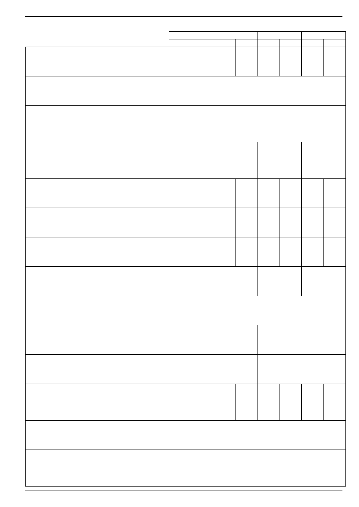
2 SPECIFICHE DI PRODOTTO 2 PRODUCT SPECIFICATIONS
2.1 Caratteristiche elettriche. 2.1 Electrical characteristics.
Le caratteristiche elettriche della pompa sono descritte sulla
targhetta di identificazione del motore elettrico (nr.8).
The electrical characteristics of the pump are reported on the
motor rating plate (no.8).
2.2 Caratteristiche della pompa. 2.2 Pump specifications.
Ulteriori informazioni sulle caratteristiche della pompa sono
riportate nelle tabelle dei dati tecnici.
Further information on the pump specifications are reported in
the technical data table.
3 INSTALLAZIONE 3 INSTALLATION
3.1 Disimballo. 3.1 Unpacking.
Controllate che l'imballo non sia danneggiato, in caso
contrario controllate che la pompa funzioni correttamente.
Make sure packing is not damaged. If not, check that pump
works properly.
In caso di danni inviate reclamo scritto al trasportatore
indicando anche il numero di DDT, data e successivamente
notificate l'inconveniente al venditore.
In the event of damage, send a claim in writing to the
forwarder, reporting the consignment note number and date,
then notify damage to the seller.
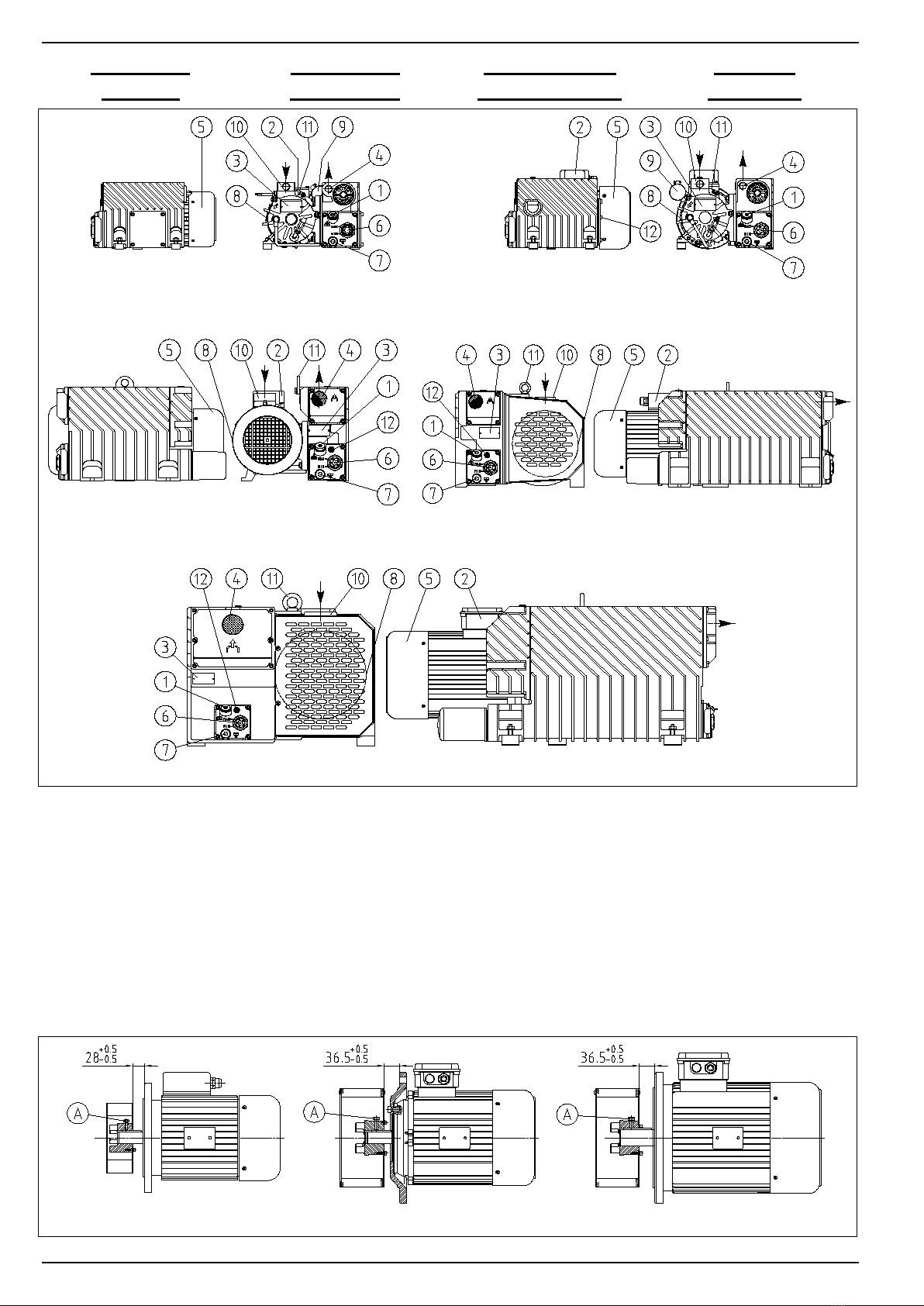
3.2 Installazione motore. 3.2 Motor installation.
E’ possibile installare qualunque tipo di motore elettrico o
idraulico che abbia le caratteristiche richieste nella tabella dei
dati tecnici, con flangia e albero corrispondenti alla grandezza:
M100/4 forma B5, secondo le norme IEC-72 per LC.105 ed
LC.150;
M112/4 forma B14, secondo le norme IEC-72 per LC.205;
M132/4 forma B5, secondo le norme IEC-72 per LC.305.
It is possible to install any electric or hydraulic motor that has
the features described in table of technical data, with flange
and shaft corresponding to:
M100/4 - B5 size as per standard IEC-72 for LC.105 and LC.150;
M112/4 - B14 size as per standard IEC-72 for LC.205;
M132/4 - B5 size as per standard IEC-72 for LC.305.
ATTENZIONE: montare il gruppo giunto/ventola sul motore
seguendo le istruzioni seguenti.
Inserire il gruppo giunto/ventola sull’albero motore fino ad
ottenere la quota indicata, quindi serrare la vite A per rendere
solidale il gruppo all’albero motore (vedi figura pag. 3).
WARNING: Install fan/coupling assembly following this
instruction.
Fit the assembly on the motor shaft up to reaching the stated
measure, then tight the A marked screws to firmly fix the
assembly to the shaft (see picture page 3).
3.3 Sistema utilizzatore. 3.3 User system.
Assicuratevi che il sistema utilizzatore non sia contaminato da
sostanze nocive durante le operazioni di installazione.
Make sure that no harmful substances contaminate the user
system during installation.
Montate una valvola di isolamento fra pompa e
sistema se desiderate che questo rimanga in vuoto
anche a pompa ferma. If you wish the system to maintain vacuum even
when pump is stopped, install a cutoff valve
between pump and system.
Assicuratevi che non vengano trasmesse vibrazioni o carichi
sull'attacco della pompa.
Make sure that no vibrations or stresses are transmitted to the
pump connection.
3.4 Alloggiamento. 3.4 Positioning.
Utilizzate appositi stumenti di sollevamento
applicati al golfare (nr.11) per sollevare la
pompa.
Use suitable lifting equipment secured to the
eyebolt (no.11) to lift the pump.

17/05/07 – R.2 LV.25 - LB.25 - LB.40 - LB.60 - LC.105 – LC.150 – LC.205 – LC.305 8702013
D.V.P. Vacuum Technology s.r.l. Pag. 11
Per assicurare il perfetto funzionamento è necessario che questa venga alloggiata
in vani areati. Si deve evitare assolutamente che l'aria calda ristagni all'interno di
suddetto vano. Non collocate nessun elemento vicino alla ventola di
raffreddamento del motore in modo che impedisca il normale afflusso dell'aria.
The pump should be placed in a ventilated room in order to
ensure its proper working. Make sure warm air is let out of the
installation room. No elements should be placed near the
motor cooling fan as this may inhibit regular air flow.
Collocate la pompa in modo che siano facilmente accessibili e visibili i tappi di
carico e scarico olio e la spia di livello.
La pompa è dotata di piedini di fissaggio; è necessario provvedere al fissaggio
della stessa per evitare pericoli di ribaltamento in caso di trasporto del sistema. La
pompa deve essere montata su un piano perfettamente orizzontale.
Place pump so that oil filler and drain plugs as well as Oil sight glass
are well visible and easily accessible.
The pump is fitted with vibration-damping feet that are also used to
fasten it. Secure the pump so it will not fall aside should the system be
relocated. The pump should be installed on a perfectly level surface.
3.5 Riempimento del serbatoio. 3.5 Filling the tank.
Non riempite il serbatoio olio oltre il livello
massimo consentito.
When filling the oil tank never exceed allowed
maximum level.
Ogni pompa è spedita senza olio nel serbatoio.
Utilizzate solo olio DVP. All pumps are shipped out dry.
Use DVP oil only.
I numeri seguenti si riferiscono al disegno riportato a pag. 3.
The numbers reported below are for cross-reference to the drawing on page
3.
Svitate il tappo di carico (nr.1); Undo filler plug (no.1);
Versate l'olio nel serbatoio fino a quando il livello
raggiunge la metà della spia (nr.6.);
Fill oil into the tank up to mid-range of Oil sight glass
(no.6);
Richiudete il tappo di carico e pulite il serbatoio da
eventuali gocce di olio.
Close filler plug and wipe off any oil spills from the tank.
3.6 Collegamento elettrico. 3.6 Wiring.
Il collegamento elettrico deve essere effettuato da
personale qualificato rispettando le normative
elettriche vigenti.
Wiring should be performed by properly skilled
personnel and in compliance with electrical
standards in force.
Controllate che la tensione di alimentazione
corrisponda a quella indicata sulla targhetta del motore
(nr.8).
Controllate il corretto senso di rotazione.
Make sure that supply voltage matches that on
motor rating plate (no.8).
Check that direction of rotation is correct.
Installate sempre un sistema di protezione elettrica tra la
pompa e la rete di alimentazione.
An electric protection system should always be provided
between pump and mains.
Troverete i valori di assorbimento sulla targhetta del motore. Electrical input values are reported on motor rating plate.
La pompa viene fornita normalmente senza cavo elettrico e
interruttore; per il collegamento alla rete elettrica riferitevi allo schema
contenuto all'interno della scatola morsettiera o sulla targhetta motore.
The pump normally comes without power cable and switch; for
connection to mains see the diagram inside the terminal board
or on the motor rating plate.
3.7 Connessioni dell'aspirazione e dello scarico. 3.7 Intake and outlet connections.
È rigorosamente vietato aspirare gas quali ossigeno
o sue miscele perchè possono causare deflagrazioni.
It is strictly forbidden to intake gases like oxygen or
oxygen mixtures as this will lead to explosion
hazard.
Non utilizzate tubazioni rigide per la connessione
dell'aspirazione e dello scarico, (MAX
sovrapressione allo scarico: 0,3 bar). E' necessario
collegare correttamente la pompa al sistema
utilizzatore.
Do not use stiff pipes to connect intake and outlet
(MAX overpressure at outlet: 0.3 bar).
Take care to connect pump to user system
correctly.
Evitare comunque: tubazioni in gomma telata, diametri troppo
piccoli (mai minori del diametro di aspirazione); lunghezze
eccessive, curve strette e frequenti.
Never use: friction hoses, too small diameters (never smaller
than intake diameter); avoid exceeding hose lenghts, tight
bends or bends spaced too closely.
Utilizzate sempre un filtro in aspirazione
specialmente se la pompa lavora con flussi non
puliti.
Always install an intake filter, especially if the pump is
to work with flux that might contain foreign matters.
Evitate che i gas di scarico ristagnino
nell'ambiente di lavoro.
Make sure that discharged gases are let out of the
workplace.
I gas di scarico della pompa devono essere trattati in modo che
non vadano a contaminare l'ambiente di lavoro e l'atmosfera
circostante.
The gases discharged by the pump should be handled in such a
way to prevent them from polluting the workplace and
surroundings.
Se vengono aspirati vapori condensabili occorre che la condensa
formatasi nella linea di scarico non si accumuli né rifluisca nella
pompa; la tubazione quindi dovrà essere discendente e priva di
anse.
If condensable vapours are pumped, the discharge hose should be
routed downwards and have no bends to prevent the condensate
produced in the discharge line from building up or flowing back into
the pump.
3.8 Indicatore di livello elettrico. 3.8 Electrical oil level gauge

8702013 LV.25 - LB.25 - LB.40 - LB.60 - LC.105 – LC.150 – LC.205 – LC.305 17/05/07 – R.2
Pag. 12 D.V.P. Vacuum Technology s.r.l.
Qualora installato, l'indicatore di livello fornisce un segnale quando il
livello dell'olio contenuto nel serbatoio scende sotto il livello minimo.
Le caratteristiche dell'indicatore sono le seguenti:
If installed, the electrical oil level gauge signals when level
inside the tank descends below minimum level.
Oil level gauge characteristics are as follows:
VOLTAGE SWITCHING: Max 250 Vdc & Vac; CURRENT SWITCHING: Max 0,5Adc / Max 0,7Aac ; CONTACT RATING: Max 50 VA
4 USO 4 USAGE
4.1 Flussi aspirabili. 4.1 Allowed intake flux.
La pompa è stata progettata per lavorare con aria pulita, gas inerti
o vapori d'acqua. La temperatura dei gas aspirati dovrà essere
compresa tra 12 e 40 °C. Non è possibile impiegare la pompa per
l'aspirazione di gas aggressivi, nocivi, inquinanti e ossigeno.
The pump was designed to work with clean air, inert gases or
steam. The temperature of intake gases must be between 12
and 40 °C. The pump must not be used to intake aggressive,
harmful, polluting gases or oxygen.
La serie L è idonea all'evacuazione di contenitori chiusi, oppure al
funzionamento in continuo a pressioni assolute specificate in §
2.2.
The L series is suitable for emptying closed containers or for
continuous duty at the absolute pressures specified in § 2.2.
Nel caso di aspirazione di vapori di acqua è indispensabile, prima di
iniziare il ciclo di lavoro, portare a temperatura di regime la pompa
facendola funzionare per circa 30 min. con la bocca d'aspirazione
chiusa.
If water steam should be taken in, take the pump to a
steady temperature by leaving it run for roughly 30 minutes
with the suction inlet closed before starting the work cycle.
4.2 Versione FKM. 4.2 FKM version.
La pompa costruita secondo questa versione è dotata di particolari accorgimenti
come le guarnizioni in FKM che ne permettono l'impiego anche con alcuni gas
aggressivi. E' comunque necessario contattare il costruttore per assicurarsi se il gas
aggressivo in oggetto rientra tra quelli con cui la pompa può lavorare.
This pump version is designed with some special equipment,
such as gaskets made of FKM
for use with some aggressive
gases. However, contact the seller to make sure the pump is
suitable for use with a given aggressive gas.
4.3 Procedura di avviamento. 4.3 Start-up.
Assicuratevi che lo scarico della pompa non sia
ostruito dai raccordi.
La pompa pùo raggiungere temperature elevate
durante il funzionamento.
Make sure that pump outlet is not obstructed by
the couplings.
The pump may reach high temperatures when
operating.
È vietato utilizzare la pompa come compressore. The pump must not be used as a compressor.
Dopo l'accensione della pompa questa può funzionare a un regime di
rotazione inferiore a quello normale se la temperatura ambiente è
inferiore a quella consentita (vedi §2.2) oppure se l'olio è contaminato,
oppure se la tensione di alimentazione è inferiore a quella richiesta.
After start-up, the pump may run slower than regular r.p.m. if
room temperature is lower than allowed (see §2.2), or if oil is
contaminated or supply voltage lower than required voltage.
Se il regime di rotazione non raggiunge il valore nominale in pochi secondi
deve scattare l'interruttore termico installato a protezione della pompa (§
3.6).
If nominal r.p.m. is not reached within a few seconds, the
thermal switch fitted to protect the pump must trip (§ 3.6).
Assicuratevi che la pompa lavori a valori di pressione
consentiti (vedi §2.2). Evitare che la pompa funzioni
per lunghi periodi con la bocca d'aspirazione
completamente aperta. Al fine di limitare il consumo
energetico e di non danneggiare la pompa è
consigliabile non effettuare più di 12 avviamenti ogni
ora.
Make sure that the pump runs at the admitted
pressure values (see § 2.2). Do not leave the pump
running for a long time with the suction inlet
completely open. It is advisable not to start the
pump more than 12 times per hour to avoid energy
consumption and damage to the actual pump.
4.4 Spegnimento. 4.4 Power off.
In caso di spegnimento raccomandiamo di fare funzionare la
pompa con l'aspirazione chiusa per circa 30 minuti.
Questa operazione permette di smaltire l'eventuale umidità
presente nella camera di aspirazione evitando l'ossidazione del
rotore.
If pump is to be powered off, let it run with closed intake for
about 30 minutes first.
This will eliminate any moisture inside the intake chamber and
avoid rotor oxydation.
5 MANUTENZIONE 5 MAINTENANCE
5.1 Informazioni generali. 5.1. General information.
Seguite attentamente le istruzioni di seguito
elencate, in caso contrario si potrebbero verificare
situazioni pericolose per l'operatore e la pompa.
Follow the instructions carefully, otherwise
hazard may arise for both operator and pump.
Isolate sempre la pompa dalla rete elettrica in modo che
non possa avviarsi accidentalmente.
Always disconnect pump from mains to prevent
unintentional starting.
Non operate sulla pompa fino a quando questa non ha
raggiunto una temperatura non pericolosa per l'operatore.
Do not work on the pump when it is so hot as to endanger
operator's safety.

17/05/07 – R.2 LV.25 - LB.25 - LB.40 - LB.60 - LC.105 – LC.150 – LC.205 – LC.305 8702013
D.V.P. Vacuum Technology s.r.l. Pag. 13
Non eseguite nessuna manutenzione se non avete già
disponibili tutti i pezzi di ricambio.
Maintenance work should only be carried out after making
sure that all spare parts required are available.
Assicuratevi che l'operatore sia tecnicamente preparato ad
operare su pompe per vuoto e che segua tutte le norme
vigenti riguardanti gli strumenti di protezione individuali.
Make sure that operator is specifically trained for operating
vacuum pumps and observes all rules in force about
individual protection equipment.
Non eseguite operazioni di manutenzione che non siano
previste da questo manuale.
No maintenance work should be carried out other than that
specified in these instructions.
5.2 Manutenzione programmata. 5.2 Scheduled maintenance.
La tabella sotto riportata mostra tutti gli interventi necessari
agli intervalli indicati per mantenere in perfetta efficienza la
pompa.
The table below shows all maintenance work to be carried out
at given intervals to keep pump in good running order.
Operazione hMaintenance work
[A] Controllo livello olio 24 [A] Check oil level
[B] Cambio olio 500 [B] Change oil
[C] Pulizia del radiatore, della protezione ventola
motore e pulizia generale della pompa 1.000 [C] Clean radiator, motor fan guard and Clean pump
[D] Sostituzione filtro depuratore 2.000 [D] Change the air exhaust filter
[E]
Sostituzione filtro olio (solo per LB.40, LB.60, LC.105, LC.150, LC.205 ed
LC.305)
1.000 [E]
Change oil filter (only for LB.40, LB.60, LC.105, LC.150, LC.205 and
LC.305)
[F] Cambio palette 10.000 [F] Change vanes
Manutenzioni più frequenti possono rendersi necessarie in base
al tipo di utilizzo (alte temperarture dei gas aspirati, presenza
nei gas aspirati di vapori condensabili).
Shorter maintenance intervals may be required according to
operating conditions (high temperature of intake gases, intake
gases containing condensable vapours).
5.3 Controllo dell'olio [A]. 5.3 How to check oil [A].
Controllate che il livello dell'olio sia a metà della spia di livello (nr.6),
in caso contrario procedete secondo le istruzioni del paragrafo
seguente.
Oil level should be at mid-range on Oil sight glass (no.6). If
not so, see instructions in following paragraph.
Controllate lo stato dell'olio; se appare scuro o torbido è segno
che è inquinato da sostanze aspirate e deve essere sostituito
seguendo le istruzioni del paragrafo seguente.
Check oil conditions. When dark or cloudy, oil has been
contaminated by intake substances and must be changed
following the instructions in following paragraph.
5.4 Sostituzione dell'olio [B]. 5.4 How to change oil [B].
Qualora le condizioni dell'olio lo richiedano procedete alla sua
sostituzione come segue tenendo presente le indicazioni date in
§5.1.
Change oil as required. Follow the instructions below and bear
in mind the information given in §5.1.
1. Fate funzionare la pompa per circa 15 minuti in modo che
l'olio fluidifichi;
1. Let the pump run for about 15 minutes so oil will become
thinner;
2.
Arrestate la pompa e scollegatela dalla rete come descritto in §5.1.
2.
Stop pump and disconnect it from mains as explained in §5.1;
3. Svitate il tappo di riempimento (nr.1); 3. Undo filler plug (no.1);
4.
Procuratevi un recipiente con capienza sufficiente per
contenere tutto l'olio (vedi §2.2) ed aprire il tappo di scarico
olio (nr.7);
4. Get a container large enough to hold all oil (see §2.2) and
open oil drain plug (no.7);
5. Fate defluire completamente l'olio se possibile inclinando
leggermente la pompa;
5. Drain out all oil and tilt pump sligthly if possible;
6. Chiudete il rubinetto di scarico e introducete l'olio nuovo
dal foro di riempimento aperto precedentemente fino a
quando il livello raggiunge la metà della spia (nr.6);
6. Close drain cock and fill in fresh oil trough the filler plug
up to mid-range on Oil sight glass (no. 6);
7. Ripristinate il collegamento elettrico; 7. Connect to mains again;
8. Avviate per alcuni minuti la pompa con l'aspirazione
chiusa, e ripristinate il livello dell'olio se necessario.
8. Let the pump run with closed intake for a few minutes. Top
up oil if necessary.
5.5
Pulizia del radiatore, della protezione ventola motore e della pompa [C].
5.5 How to clean radiator, motor fan guard and pump [C].
La pulizia del radiatore, della protezione ventola e della pompa è
necessaria per rimuovere i depositi di polvere. Questa operazione
si effettua utilizzando un soffio d'aria compressa e un panno
asciutto.
Non utilizzate liquidi o altre sostanze diverse da quelle
indicate.
Radiator, casing and pump should be cleaned to remove any
dust deposits. This can be done using compressed air and a dry
cloth.
Do not use any fluids or substances other than those indicated.
5.6 Sostituzione del filtro depuratore [D]. 5.6 How to change air exhaust filter [D].
Le istruzioni per la sostituzione del depuratore sono disponibili a richiesta.
The instructions for replacing the cleaner are are avaible on
request.

8702013 LV.25 - LB.25 - LB.40 - LB.60 - LC.105 – LC.150 – LC.205 – LC.305 17/05/07 – R.2
Pag. 14 D.V.P. Vacuum Technology s.r.l.
5.7 Sostituzione filtro olio (solo per LB.40, LB.60, LC.105,
LC.150, LC.205 e LC.305) [E]
5.7 How to change oil filter (only for LB.40, LB.60, LC.105,
LC.150, LC.205 and LC.305) [E]
Le istruzioni per la sostituzione del filtro olio sono disponibili a
richiesta.
The instructions for replacing the oil filter are available on
request.
5.8 Sostituzione palette [F]. 5.8 How to change vanes [F].
Le istruzioni per la sostituzione delle palette sono disponibili a
richiesta.
The instructions for changing vanes are avaible on request.
5.9 Individuazione dei guasti. 5.9 Troubleshooting.
Qualora la pompa non funzioni correttamente controllate anzitutto che
il problema lamentato non venga risolto da una delle operazioni
seguenti. Se il problema non venisse risolto contattate il servizio
assistenza.
If the pump malfunctions, try the following measures first to
eliminate the trouble. If trouble persists, contact service
department.
Difetto Causa / Rimedio Fault Cause / Remedy
A) La pompa
non funziona.
1) Interruttore termico scattato; Verificare le cause
che lo hanno generato e attivare l'interruttore.
2)
Temperatura ambiente troppo bassa; Portare la
temperatura ambiente entro l'intervallo consentito (§ 2.2).
3) Avvolgimento motore rotto; Rivolgersi
al servizio assistenza.
A) Pump does
not run.
1) Thermal switch has tripped; Identify
reason and activate switch.
2) Room temperature is too low; Restore
room temperature to allowed range (§2.2).
3) Motor winding damaged; Contact
Service Department.
B) La pompa
non raggiunge
il vuoto
dichiarato.
1) Olio insufficiente nel serbatoio;
Aggiungere olio (§ 3.5).
2) Olio contaminato; Sostituire olio (§ 5.4).
3) Scarico ostruito; Controllare i raccordi
allo scarico.
B) Pump
cannot reach
stated vacuum.
1) Low oil in tank; Top up oil (§ 3.5).
2) Oil is contaminated; Change oil (§ 5.4).
3) Discharge clogged; Check couplings at
outlet.
C) La pompa è
rumorosa.
1)
Filtro depuratore deteriorato; Sostituire (§ 5.6).
2) Cuscinetti motore danneggiati;
Rivolgersi al servizio assistenza.
3) Giunto motore danneggiato (solo per
LC.105, LC.150, LC.205 e LC.305);
Rivolgersi al servizio assistenza.
4) Palette deteriorate; Rivolgersi al servizio
assistenza.
C) Pump is
noisy.
1) Air exhaust filter clogged; Change aie
exhaust filter (§ 5.6).
2) Motor bearings damaged; Contact
Service Department.
3) Motor coupling damaged (only for
LC.105, LC.150, LC.205 and LC.305);
Contact Service Department.
4)
Vanes worn out; Contact Service Department.
D) Temperatura
della pompa
elevata.
1) Olio non adatto; Sostituire l'olio (§ 5.4).
2) Insufficiente ventilazione ambientale;
Installare un ventilatore ausiliario.
3) Ventola motore rotta; Rivolgersi al
servizio assistenza.
4) Alimentazione motore non corretta;
Controllare la tensione di alimentazione.
5) Scarico ostruito; Vedi B.3.
D) Pump runs
hot.
1)
Oil is not the suitable type; Change oil (§
5.4).
2) Poor room ventilation; Install an
auxiliary ventilator.
3) Motor fan broken; Contact Service
Department.
4) Wrong power supply to motor; Check
power supply.
5) Outlet clogged; See B.3.
E) Alto
consumo di
olio.
1) Pressione di lavoro elevata (prossime
alla pressione atmosferica); Tenere
controllato il livello olio.
2) Temperatura della pompa troppo alta; Vedi D.
3) Filtro depuratore deteriorato; Sostituire (§
5.6).
E) High oil
consumption.
1)
High working pressure (close to atmospheric
pressure); Check oil level frequently.
2) Pump temperature too high; See D.
3) Air exhaust filter damaged; Replace air
exhaust filter (§5.6).
F)
La pompa non
rimane in vuoto
dopo lo
spegnimento.
1) Valvola antiritorno (ove installata)
deteriorata; Rivolgersi al servizio
assistenza.
F)
Pump does not
maintain vacuum
after power-off.
1) Check valve (if fitted) damaged; Contact
Service Department.
G) Perdite di
olio dalla
pompa.
1) Viti serbatoio o tappi non serrati; Serrate
le viti o i tappi.
2) Guarnizione serbatoio danneggiata;
Rivolgersi al servizio assistenza.
3) Spia di livello non serrata; Serrate la
spia di livello.
G) Pump leaks
oil.
1) Tank screws or knobs loosened; Tighten
screws or knobs.
2) Tank gaskets damaged; Contact Service
Department.
3) Oil sight glass not tightened; Tighten
Oil sight glass.
6 IMMAGAZZINAGGIO TRASPORTO E
ROTTAMAZIONE
6 STORAGE, TRANSPORT AND DISPOSAL
6.1 L'immagazzinaggio. 6.1 Storage.

17/05/07 – R.2 LV.25 - LB.25 - LB.40 - LB.60 - LC.105 – LC.150 – LC.205 – LC.305 8702013
D.V.P. Vacuum Technology s.r.l. Pag. 15
L'immagazzinaggio della pompa deve avvenire dopo che la
stessa è stata riempita con olio nuovo vedi §5.4.
The pump should be cleaned and filled with fresh oil (see §5.4)
before storage.
Chiudete l'aspirazione e lo scarico con le apposite protezioni e
immagazzinatela in un ambiente in cui la temperatura sia
compresa nell'intervallo indicato in §2.2.
Close intake and outlet with suitable protections and store
pump in a room where temperature is within the range
specified in § 2.2.
6.2 Trasporto. 6.2 Transport.
In caso di trasporto la pompa preparata come sopra può viaggiare
comunque coperta in condizioni climatiche come riportato in §2.2.
Per la durata del trasporto è consigliato svuotare il serbatoio
dall'olio seguendo le indicazioni date in §5.4.
Before transport, prepare pump as for storage, and cover it.
Temperature range is referred to §2.2.
Drain oil from tank before transport (see instructions in §5.4).
6.3 Rottamazione. 6.3 Disposal.
Lo smaltimento della pompa deve essere fatto rispettando le
norme delle rispettive legislazioni nazionali.
Pump should be disposed of in compliance with local national
standards.
In particolare non è consentito disperdere l'olio usato le
guarnizioni e le palette nell'ambiente.
In particular, spent oil, gaskets and vanes must be disposed of
in accordance with environment protection rules.
7 RICAMBI 7 SPARE PARTS
Nell'acquisto dei ricambi citate sempre il numero di matricola
e il modello della pompa nonché il codice del ricambio.
Qualora la pompa utilizzi guarnizioni in FKM occorre citare
anche tale caratteristica nella richiesta di ricambi.
When purchasing spare parts, always quote the serial number and
model of the pump, as well as the spare part purchase number.
If the pump mounts FKM
gaskets, this should also be reported
in the spare parts order.
Descrizione LV.25 LB.25 LB.40 LB.60 LC.105 LC.150 LC.205 LC.305 Description
Kit filtro
depuratore
K960105
6
K960104
9
K960104
6
K960104
7
K960302
1
K960302
2
K960302
3
K960302
4
Air exhaust
filter kit
Kit
manutenzione
K9601056/
1
K9601049/
1
K9601046/
1
K9601047/
1
K9603021/
1
K9603022/
1
K9603023/
1
K9603024/
1
Maintenance kit
Olio 1 dm38812100 (BV68) / 8832100 (SW60) - - - - - Oil, 1 dm3
Olio 2 dm38812200 (BV68) / 8832200 (SW60) - - - - - Oil, 2 dm3
Olio 5 dm38812500 (BV68) / 8832500 (SW60) 8813500 (BV100) / 8833500 (SW100) Oil, 5 dm3
Filtro olio - - - - - 1809001 1809002 Oil filter
Spia livello
olio 1105004 Oil sight glass
8 RITORNO DELLA POMPA 8 HOW TO RETURN THE PUMP
E' importante riportare sempre il codice, il numero di matricola e
la data di acquisto della pompa in ogni comunicazione con il
fornitore.
La pompa in ogni caso non può essere resa senza precedenti
accordi con lo stesso.
E' necessario in caso di riparazione dichiarare oltre ai dati
sopracitati anche l'esatta anomalia riscontrata e le sostanze che
sono venute a contatto con la pompa e i rischi che la
manipolazione della pompa può comportare.
Pump type, serial number and purchase date should always be
mentioned in all correspondence with the supplier.
The pump may only be returned after prior agreement with
the supplier.
Should the pump need repair, the above information should be
supplemented with the accurate description of the malfunction,
which substances have been in contact with the pump, and
which hazards are involved in handling the pump.
( D ) ( E )
1 EINFÜHRUNG 1 INTRODUCCION
1.1 Zweck der Anleitung. 1.1 Finalidad del manual.
Diese erläutert die korrekten Vorgehensweise für das
Auspacken, die Installation, den Gebrauch, die Wartung die
Einlagerung und die Verschrottung der Pumpen der Serie L.
Bevor Sie mit der Arbeit beginnen, lesen Sie aufmerksam die
in dieser Anleitung enthaltenen Anweisungen. Inder Anleitung
wird zweierlei Symbolik verwendet:
El presente manual ilustra los correctos procedimientos para el
desembalaje, la instalación, el uso, el mantenimiento, el
almacenaje y la eliminación de las bombas de la serie L. Antes
de comenzar a trabajar leer atentamente las instrucciones
contenidas en el presente manual. En el manual se emplean
dos tipos de símbolos:

8702013 LV.25 - LB.25 - LB.40 - LB.60 - LC.105 – LC.150 – LC.205 – LC.305 17/05/07 – R.2
Pag. 16 D.V.P. Vacuum Technology s.r.l.
Die erste bezieht sich auf Anweisungen, die, läßt man sie
unbeachtet, die Pumpe beschädigen können.
El primero se refiere a las instrucciones que deben respetarse
para no causar daños a la bomba.
Die zweite bezieht sich auf Anweisungen, die, läßt man sie
unbeachtet, gefährliche Bedingungen für das Bedienungspersonal
schaffen können.
Alle inder vorliegenden Anleitung verwendeten Maßeinheiten
stimmen mit dem System SI (Internationales Meßsystem)
überein.
Die Eigenschaften der Produkte können ohne vorherige
Benachrichtigung verändert werden.
El segundo se refiere a las instrucciones que deben respetarse
para no originar situaciones de peligro para el operador.
Todas las unidades de medida utilizadas en el presente manual
responden al sistema SI (Sistema Internacional de las Unidades
de Medida).
Las caracteìsticas de los productospueden variar sin previo
aviso.
2 PRODUKT- SPEZIFIKATIONEN 2 ESPECIFICACIONES DEL PRODUCTO
2.1 Elektrische Eigenschaftene. 2.1 Características eléctricas.
Die elektrischen Eigenschaften der Pumpe sind auf dem
Leistungsschild des Elektromotors beschrieben. (Nr. 8).
Las características eléctricas de la bomba se encuentran
descritas en la ficha de identificación del motor eléctrico (nr.
8).
2.2 Pumpeneigenschaften. 2.2 Características de la bomba.
Weitere Infos über die Eigenschaften der Pumpe finden Sie
bitte in den Tabellen mit den technischen Daten.
Infomation posterior complementaria sobre las Características
de le bomba se encuentran en la tabla de datos técnicos.
3 INSTALLATION 3 INSTALACION
3.1 Auspacken. 3.1 Desembalaje.
Kontrollieren Sie, daß die Verpackung nicht beschädigt ist. Wenn das
nicht der Fall ist, kontrollieren Sie, ob die Pumpe einwandfrei funktioniert.
Controlar que el embalaje no se encuentre perjudicado, en caso
contrario controlar que la bomba funcione correctamente.
Im Fall von Beschädigungen schicken Sie dem Spediteur eine
schriftliche Beschwerde, geben dabei auch die Nummer des
Warenbegleitscheins und Datum an und melden Sie dem
Verkäufer den bedauerlichen Zwischenfall.
En caso de daños enviar reclamación escrita al transportador
indicando además el número de resguardo y fecha,
sucesivamente comunicar el inconveniente al vendedor.
3.2 Motorinstallierung. 3.2 Instalación del motor.
Es kann jede Art von Elektro- bzw. Hydraulikmotor eingebaut
werden, der über die in der Tab. technische daten aufgeführten
Merkmale verfügt, mit Flansch und Welle der Baugröße:
M100/4, Form B5, gemäß IEC-72 für LC.105 und LC.150;
M112/4, Form B14, gemäß IEC-72 für LC.205;
M132/4, Form B5, gemäß IEC-72 für LC.305.
Es posible instalar cualquier tipo de motor eléctrico o
hidráulico que tenga las características necesarias con brida y
árbol correspondientes a la magnitud:
M100/4 forma B5, según las normas IEC-72 per LC.105 y LC150;
M112/4 forma B14, según las normas IEC-72 per LC.205;
M132/4 forma B5, según las normas IEC-72 per LC.305.
ACHTUNG: Montieren Sie die Gruppe Kupplung/ügelrad auf
dem Motor nach folgenden Anweisungen:
Die Gruppe Kupplung/ügelrad auf der Motorwelle einsetzen,
bis wann die, wie in der unteren Zeichnung, eingegebene
Gröβe erreicht wird. Dann die Schraube A anziehen, um die
Gruppe an die Motorwelle zu befestigen (siehe Seite 3).
ATENCIÓN: montar el grupo cardán/ventilador en el motor
siguiendo las siguientes instrucciones:
colocar el grupo cardán/ventilador sobre el árbol motor hasta
obtener la altura indicada; luego apretar el tornillo A para unir
el grupo al árbol motor (ver pàgina 3).
3.3 Benutzersystem. 3.3 Sistema utilizador.
Versichern Sie sich, daß das Benutzersystem während der
Installation nicht durch Schadstoffe verunreinigt wird.
Controlar que el sistema utilizador no se contamine con
sustancias perjudiciales durante las operaciones de instalación.
Wenn Sie wünschen, daß das System auch bei
Pumpenstillstand im Vakuum bleibt, montieren Sie
ein Absperrventil zwischen Pumpe und System.
Montar una válvula de aislamiento entre la
bomba y el sistema si desean que este último
permanezca siempre en vacio también con la
bomba parada.
Versichern Sie sich, daß keine Schwingungen oder
Belastungen auf den Pumpenanschluß übertragen werden.
Cerciorarse que no se transmitan vibraciones o cargas en el
enganche de la bomba.
3.4 Aufstellung. 3.4 Posicionamiento.
Zum heben der Pumpe verwenden Sie eigen
dafür vorgesehene an der Ösenschraube
befestigte Hebevorrichtungen (Nr.11).
Utilizar específicos instrumentos de elevación
aplicados a la armella (nr.11) para el
levantamiento de la bomba.
Zur Sicherung eines perfekten Betriebs ist es notwendig, daß
die Pumpen in belüfteten Räumen untergebracht wird. Man
muß auf jeden Fall vermeiden, daß sich warme Luft in oben
genanntem Raum staut.
Stellen Sie kein Element, das den normalen Luftzustrom
hemmen könnte, nahe bei dem Motorlüfter auf.
Para asegurar el perfecto funcionamiento es necesario que la
misma se ubique en sitios ventilados. Se debe evitar
absolutamente que el aire caliente permanezca dentro del antes
mencionado alojamiento. No posicionar ningún elemento en
proximidad del ventilador de refrigeración del motor que
pueda impedir la normal circulación del aire.

17/05/07 – R.2 LV.25 - LB.25 - LB.40 - LB.60 - LC.105 – LC.150 – LC.205 – LC.305 8702013
D.V.P. Vacuum Technology s.r.l. Pag. 17
Die Pumpe so anschließen, daß die Öleinfüll-und-ablaßstopfen
und die Pegelkontrolle leicht erreichbar sind.
Die Pumpe ist mit Füßchen zur Befestigung ausgerüstet, es ist
daher nötig für ihre Befestigung zu sorgen,um die Umkippgefahr
im Falle eines Transports des Systems zu vermeiden. Die Pumpe
muß auf einer perfekt horizontale Fläche aufgestellt werden.
Colocar la bomba en forma tal que los tapones de carga y
descarga aceite y el indicador de nivel sean facilmente accesibles
y visibles.
La bomba ha sido equipada con pies de fijación; es necesario fijar
la máquina para evitar peligros de volcado en caso de transporte
del sistema. La bomba debe montarse en una superficie plana
perfectamente horizontal.
3.5 Füllen des Tanks. 3.5 Llenado del depósito.
Füllen Sie den Öltank nicht über den
zugelassenen Maximalpegel hinaus.
Al llenar el depósito aceite no superar el nivel
máximo admitido.
Jede Pumpe kommt ohne Öl im Tank zum
Versand. Verwenden Sie nur DVP-Öl. Cada bomba se suministra sin aceite en el
depósito. Utilizar solo aceite DVP.
Die folgenden Nummern beziehen sich auf die auf Seite 3
wiedergegebene Zeichnung.
Los siguientes números se refieren al diseño de página 3.
Schrauben Sie den Stöpsel zur Einfüllung (Nr.1) ab; Destornillar el tapón de carga (nr.1);
Füllen Sie Öl in den Tank bis der Pegel die Mitte des
Standanzeigers (Nr.6) erreicht;
Versar el aceite en el depósito hasta que el nivel alcance la
mitad del indicador (nr.6);
Schrauben Sie den Stöpsel zur Einfüllung wieder auf und
wischen Sie etwaige Öltropfen vom Tank ab.
Cerrar el tapón de carga y limpiar eventuales gotas de
aceite del depósito.
3.6 Elektrischer Anschluß. 3.6 Conexión eléctrica.
Der elektrische Anschluß muß unter Beachtung
der gültigen Elektronormen durch Fachpersonal
vorgenommen werden.
La conexión eléctrica debe ser efectuada por
personal cualificado respetando las normas
eléctricas en vigor.
Kontrollieren Sie, daß die Versorgungsspannung
derjenigen entspricht, die auf dem Motorschild
angegeben ist (Nr.8).
Die richtige Drehrichtung Kontrollieren.
Controlar que la tensión de alimentación
corresponda con aquella indicada en la ficha del
motor (nr. 8).
Controlar el correcto sentido de rotación.
Bringen Sie immer ein Elektroschutzsystem zwischen der
Pumpe und dem Versorgungsnetz an.
Instalar siempre un sistema de protección eléctrica entre la
bomba y la red de alimentación.
Sie finden die Stromwerte auf dem Motorschild. Encontrarán los valores de absorción en la ficha motor.
Die Pumpe wird normalerweise ohne Elektrokabel und ohne
Schalter geliefert. Halten Sie sich hinsichtlich der Anschlüsse
bitte an den Plan, der im Inneren des Klemmnkastens
untergebracht ist oder sich auf dem Motorschild befindet.
Normalmente la bomba se suministra sin cable eléctrico e
interruptor; para la conexión a la red eléctrica consultar el
esquema que se encuentra contenido en el interior de la caja de
bornes o la ficha motor.
3.7 Verbindungen der Ansaugung und des Ablasses. 3.7 Conexiones de la aspiración y de la descarga.
Es ist strikt verboten, Gasarten, wie Sauerstoff
oder seine Gemische anzusaugen, da sie
Deflagrationen hervorrufen können.
Está completamente prohibido aspirar gases
como por ejemplo el oxígeno o sus mezclas porque
pueden originar deflagraciones.
Verwenden Sie keine Rohr-bzw. festen Leitungen zum
Anschluß der Ansaugung und des Ablasses, (MAX
Überdruck beim Ablaß: 0,3 bar). Es ist nötig, die
Pumpe ordungsgemäß an das Benutzersystem
anzuschließen.
No emplear tubos rígidos para la conexión de la
aspiración y de la descarga (MAX sobrepresión a
la descarga: 0,3 bar). Es necesario conectar
correctamente la bomba al sistema de uso.
Auf jeden Fall zu vermeiden sind: Leitungen aus Leinengummi,
zu kleine Durchmesser (niemals unter dem Durchmesser der
Ansaugung); übertriebene Längen, enge und häufige
Krümmungen.
En todas formas evitar: tubos de goma con refuerzo de tela,
diámetros demasiado pequeños (jamás menores del diámetro
de aspiración); largos excesivos, curvas estrechas y frecuentes.
Bei der Ansaugung verwenden Sie immer einen
Filter, vor allem dann wenn die Pumpe mit
unreinen Gase arbeitet. Utilizar siempre un filtro en aspiración, sobre
todo si la bomba trabaja con fluidos no limpios.
Vermeiden Sie, daß sich die Abgase im
Arbeitsraum stauen.
Evitar que los gases de descarga queden en el
ambiente de trabajo.
Die Abgase der Pumpe müssen so behandelt werden, daß sie nicht
den Arbeitsraum und die Atmosphäre der Umgebung vergiften.
Los gases de descarga de la bomba deben ser tratados en forma tal que
no contaminen el ambiente de trabajo y la atmósfera circunstante.
Wenn kondensierbare Dämpfe gepumpt werden, darf das
Kondenswasser, das sich in der Ablassleitung gebildet hat, sich
nicht sammeln und auch nicht in die Pumpe zurückfließen;
folglich muß die Rohrleitung abwärts geneigt sein und keine
Krümmungen haben.
Si se bombean vapores condensables es necesario que la
condensación que se forma en la línea de descarga no se
acumule y que tampoco retorne a la bomba; por esta razón el
tubo deberá descender y no deberá tener ansas.
3.8 Elektrischer Standanzeiger. 3.8 Indicador de nivel eléctrico

8702013 LV.25 - LB.25 - LB.40 - LB.60 - LC.105 – LC.150 – LC.205 – LC.305 17/05/07 – R.2
Pag. 18 D.V.P. Vacuum Technology s.r.l.
Wenn installiert, erzeugt der Standanzeiger ein Signal wenn
das Ölniveau im Tank unter dem Mindestniveau liegt.
Der Standanzeiger hat die folgenden Eigenschaften:
Si se encuentra instalado, el indicador de nivel, abastece una
señal cuando el nivel en el depósito alcanza el nivel mínimo.
Las características del indicador son las siguientes:
VOLTAGE SWITCHING: Max 250 Vdc & Vac; CURRENT SWITCHING: Max 0,5Adc / Max 0,7Aac ; CONTACT RATING: Max 50 VA
4 BETRIEB 4 UTILIZACION
4.1 Ansaugbare Gase. 4.1 Fluidos aspirables.
Die Pumpe ist entworfen worden, um mit sauberer Luft, Wasserdampf
oder Edelgasarten zu arbeiten. Die Temperatur der angesaugten Gase
muß sich innerhalb von 12 und 40 °C bewegen. Es ist nicht möglich,
die Pumpe für die Ansaugung von aggressiven, schädlichen,
verunreinigenden Gasarten und Sauerstoff zu verwenden.
La bomba ha sido estudiada para trabajar con aire limpio,
gases inhertes o vapores de agua. La temperatura de los gases
aspirados deberá estar comprendida entre 12 y 40 °C. No es
posible utilizar la bomba para la aspiración de gases agresivos,
perjudiciales, contaminantes y oxígeno.
Die Serie L eignet sich für die Entleerung von geschlossenen
Behältern, oder für den Dauerbetrieb bei absoluten
Druckwerten wie unter § 2.2 angegeben.
La serie L es adecuada para el vaciado de contenedores
cerrados, o para el funcionamiento en continuo con presiones
absolutas especificadas en § 2.2.
Beim Ansaugen von Wasserdämpfen muß die Pumpe vor
Beginn des Arbeitszyklus auf die Betriebstemperatur
gebracht werden. Dazu die Pumpe ca. 30 Minuten lang mit
geschlossener Ansaugöffnung laufen lassen.
En caso de aspiración de vapores de agua, es indispensable,
antes de comenzar el ciclo de trabajo, poner la bomba a la
temperatura de régimen, haciéndola funcionar unos 30
minutos con la boca de aspiración cerrada.
4.2 FKM-Ausführung. 4.2 Versión FKM.
Die nach dieser Ausführung gebaute Pumpe ist mit besonderen
Vorrichtungen wie den FKM-Dichtungen ausgerüstet, die deren
Verwendung auch bei einigen aggressiven Gasarten ermöglichen.
Es ist jedenfalls nötig, Kontakt mit dem Hersteller aufzunehmen,
um sich zu vergewissern, daß die betreffende aggressive Gasarte
unter die fällt, mit denen die Pumpe arbeiten kann.
La bomba construida según esta versión ha sido equipada con
especiales dispositivos como por ejemplo las juntas en FKM
que
permiten el empleo también con algunos gases agresivos. En todas
formas es necesario consultar el vendedor para cerciorarse que el
gas agresivo en objeto forma parte de aquellos gases con los
cuales la bomba puede trabajar.
4.3 Inbetriebnahme. 4.3 Procedimiento de accionamiento.
Vergewissern Sie sich, daß der Pumpenablauf
nicht verstopft ist.
Die Pumpe kann im Betrieb hohe Temperaturen
erreichen.
Controlar que la descarga de la bomba no se
encuentre obstruida por las conexiones.
La bomba puede alcanzar temperaturas elevadas
durante el funcionamiento.
Die Pumpe darf nicht als Kompressor verwendet
werden. Se prohibe el utilizo de la bomba como
compresor.
Nach der Inbetriebnahme der Pumpe kann diese mit
Drehzahlen arbeiten, die unter den normalen Drehzahlen
liegen, wenn die Raumtemperatur unter der genehmigten
Temperatur liegt (siehe §2.2) oder wenn das Öl vergiftet ist
oder wenn die Versorgungsspannung unter der geforderten
Spannung liegt.
Después del accionamiento de la bomba la misma puede
funcionar con un régimen de rotación menor al normal si la
temperatura ambiente es inferior a la temperatura admitida
(consultar §2.2), si el aceite ha sido contaminado o si la
tensión de alimentación es inferior a la necesaria.
Wenn die Drehzahlen erreicht den Nominalwert in einge
Sekunden, muß die installierte Wärmeschutzschalter sich
einsetzen, um die Pumpe zu Schützen (§ 3.6).
Si el régimen de rotación no alcanza el valor nominal en pocos
segundos deberá activarse el interruptor térmico instalado
como protección de la bomba (§ 3.6).
Es muß gewährleistet sein, daß die Pumpe mit
den zulässigen Druckwerten arbeitet (siehe
Abschnitt 2.2). Die Pumpe sollte nicht zu lange
mit ganz offener Ansaugöffnung in Betrieb
gelassen werden. Zum Einsparen von Energie
und zum Schutz der Pumpe wird empfohlen,
diese nicht mehr als 12 mal pro Stunde zu
starten.
Asegúrese que la bomba trabaje con los valores
de presión permitidos (vea §2.2). Evite que la
bomba funcione durante períodos largos con la
boca de aspiración completamente abierta. A fine
de limitar el consumo energético y de no dañar la
bomba, se aconseja no efectuar más de 12
arranques cada hora.
4.4 Abschalten. 4.4 Desconexión.
Bevor die Pumpe abgeschaltet wird ist, raten wir Ihnen, die Pumpe
ungefähr 30 Minuten lang mit verschlossen Ansaugung laufen zu
lassen. Dieser Arbeitsgang ermöglicht es, die Pumpe bei den nächsten
Inbetriebsetzungen nicht zu beschädigen, wenn aufgrund der sich in
der Ansaugkammer befindenden Feuchtigkeit der Rotor oxydieren
sollte.
En caso de desconexión de la bomba recomendamos dejar
funcionar la bomba con la aspiración cerrada durante 30
minutos. Esta operación permite la eliminación de la eventual
humedad presente en la cámara de aspiración evitando la
oxidación del rotor.
5 WARTUNG 5 MANTENIMIENTO

17/05/07 – R.2 LV.25 - LB.25 - LB.40 - LB.60 - LC.105 – LC.150 – LC.205 – LC.305 8702013
D.V.P. Vacuum Technology s.r.l. Pag. 19
5.1 Allgemeine Informationen. 5.1 Informaciones generales.
Befolgen Sie sorgfältig die in Folge aufgeführten
Anweisungen, andernfalls könnten gefährliche
Situationen für die Pumpe und das
Bedienungspersonal entstehen.
Respetar escrupulosamente las instrucciones
especificadas seguidamente, en caso contrario se
podrian dar lugar a situaciones peligrosas para el
operario y para la bomba.
Isolieren Sie immer die Pumpe von dem Elektronetz, sodaß
sie nicht zufällig anspringt.
Aislar siempre la bomba de la red eléctrica en forma tal que
no pueda accionarse accidentalmente.
Warten Sie mit allen Arbeiten, bis die Pumpe auf
ungefährliche Temperaturen abgekühlt ist.
No manipular la bomba hasta que la misma no haya alcanzado
una temperatura que no sea peligrosa para el operador.
Nehmen Sie keine Wartung vor, wenn Sie nicht schon über
alle Ersatzteile verfügen.
No efectuar ningún mantenimiento si no disponen de todas
las piezas de recambio.
Vergewissern Sie sich, daß das Bedienungspersonal vom
technischen Standpunkt her geschult ist, an
Vakuumpumpen zu arbeiten, und daß es alle geltenden
Normen befolgt, die die Mittel zum Schutz des Einzelnen
betreffen.
Cerciorarse que el operador esté técnicamente preparado
para actuar con bombas para vacio y que respete todas las
normas en vigor concernientes los instrumentos de
protección individuales.
Führen Sie keine Arbeitsgänge durch, die in dieser
Betriebsauleitung nicht erwähnt werden.
No efectuar operaciones de mantenimiento que no hayan
sido previstas por el presente manual.
5.2 Plamässige Wartung. 5.2 Mantenimiento programado.
Die unten aufgeführte Tabelle, zeigt alle, in den angegebenen
Intervallen auszuführenden Eingriffe auf, um die Pumpe in
einem perfekten Zustand zu erhalten.
La tabla indicada seguidamente presenta todas las
intervenciones necesarias y los intervalos de tiempos
adecuados para mantener en perfecta eficacia la bomba.
Arbeitsgang hOperación
[A] Ölpegelkontrolle 24 [A] Control nivel aceite
[B] Ölwechsel 500 [B] Cambio aceite
[C] Die Reinigung des Kühlers, des Motorlüfters und
allgemeine Reinigung der Pumpe 1.000 [C] Limpieza del cambiador de calor, de la protección
ventilador motor y limpieza general de la bomba
[D] Austausch des Reinigerfilters 2.000 [D] Cambio filtro depurador
[E] Austausch des Ölfilters (nur LB.40, LB.60, LC.105,
LC.150, LC.205 und LC.305) 1.000 [E] Cambio filtro aceite (solamente LB.40, LB.60,
LC.105, LC.150, LC.205 Y LC.305)
[F] Austausch der Schieber 10.000 [F] Cambio paletas
Je nach Einsatzart und Raum, im dem die Pumpe installiert wird,
können die Wartungsarbeiten öfters notwendig werden (hohe
Temperaturen der angesaugten Gasarten, Vorhandensein von
kondensierbaren Dämpfen in den angesaugten Gasarten).
Mantenimientos más frecuentes pueden ser necesarios según el
tipo de utilizo: elevadas temperaturas de los gases aspirados o
presencia en los gases aspirados de vapores condensables.
5.3 Ölkontrolle [A]. 5.3 Control del aceite [A].
Kontrollieren Sie, daß der Ölpegel die Mitte des
Standanzeigers (Nr.6) erreicht hat, andernfalls verfahren Sie
nach den Anweisungen des folgenden Abschnitts.
Controlar que el nivel del aceite se encuentre en la mitad del
indicador de nivel (nr.6), en caso contrario proceder según las
instrucciones del párrafo sucesivo.
Kontrollieren Sie den Ölzustand; wenn es dunkel oder trübe
erscheint, ist das ein Zeichen dafür, daß es aufgrund von
angesaugten Stoffen verschmutzt ist. Wechseln Sie das Öl
nach den im folgenden Abschnitt angegebenen Anweisungen
aus.
Controlar el estado del aceite, si aparece oscuro o túrbido
significa que está contaminado por sustancias aspiradas y debe
ser reemplazado respetando las indicaciones del párrafo
sucesivo.
5.4 Ölwechsel [B]. 5.4 Sustitución del aceite [B].
Sollte der Ölzustand es erfordern, wechseln sie es wie folgt aus
und richten Sie sich nach den unter §5.1 gegebenen
Anweisungen.
En la eventualidad que las condiciones del aceite lo precisen,
proceder a su sustitución en la forma siguiente, recordando las
indicaciones especificadas en §5.1.
1. Lassen Sie die Pumpe ungefähr 15 Minuten arbeiten, sodaß
das Öl flüssig wird;
1. Dejar funcionar la bomba durante aproximadamente 15
minutos para que el aceite adquiera mayor fluidez;
2. Stoppen Sie die Pumpe und unterbrechen Sie wie unter
§5.1 beschrieben, ihre Verbindung zum Netz.
2. Detener la bomba y desconectarla de la red como descrito
en §5.1;
3. Schrauben Sie den Auffüllstöpsel (Nr.1) ab; 3. Destornillar el tapón de llenado (nr.1);
4. Beschaffen Sie sich einen Behälter mit einem
Fassungsvermögen, das ausreicht, das gesamte Öl zu
enthalten (siehe §2.2) und schrauben Sie den Stöpsel
Ölausfluß ab (Nr.7);
4. Posicionar un contenedor con capacidad suficiente para
contener todo el aceite (consultar §2.2) y destornillar el
tapón de descarga (nr.7);
5. Indem Sie, wenn möglich, die Pumpe leicht neigen, lassen
Sie das Öl ganz ausfließen;
5. Dejar salir todo el aceite, si posible inclinando ligeramente
la bomba;
6. Schließen Sie den Ablaßhahm und füllen Sie durch das
vorher freigemachte Fülloch das frische Öl ein bis der
Pegel die Mitte des Standanzeigers (Nr.6) erreicht;
6. Cerrar el grifo de descarga e introducir el aceite nuevo por
el agujero de llenado abierto anteriormente hasta cuando el
nivel alcanza la mitad del indicador (nr.6).

8702013 LV.25 - LB.25 - LB.40 - LB.60 - LC.105 – LC.150 – LC.205 – LC.305 17/05/07 – R.2
Pag. 20 D.V.P. Vacuum Technology s.r.l.
7. Stellen Sie den elektrischen Anschluß wieder her; 7. Restablecer el empalme eléctrico;
8.
Lassen Sie die Pumpe einige Minuten lang mit geschlossener
Ansaugung laufen und füllen Sie, wenn nötig, das Öl wieder
auf.
8.
Accionar durante algunos minutos la bomba con la aspiración
cerrada y si fuera necesario restablecer el nivel del aceite.
5.5 Reinigung des Kühlers, des Motorlüfters und
allgemeine Reinigung der Pumpe [C].
5.5 Limpieza del cambiador de calor, de la protección
ventilador motor y de la bomba [C].
Die Reinigung des Kü hlers, der Motorschutzhaube und der Pumpe wird
vorgenommen, um etwaige Staubrü ckstä nde zu beseitigen. Sie wird durchgefü hrt
unter Zuhilfenahme eines Blasstosses Preß luft und eines trockenes Tuchs.
Benutzen Sie keine Flüssigkeiten oder andere Substanzen als die angegebenen
Mittel.
La limpieza del cambiador de calor, del carter y de la bomba es
necesaria para eliminar los depósitos de polvo. Esta operación se
realiza utilizando un soplo de aire comprimida y un trapo seco. No
utilizar líquidos u otras sustancias diferentes de aquellas
indicadas.
5.6 Austausch des Reinigerfilters [D]. 5.6 Sustitución del filtro depurador [D]
Die Anweisungen für den Austausch des Reinigerfilters sind
im Austauschsatz enthalten.
Las instrucciones para la sustitución del depurador se
encuentran son disponibles a petición..
5.7 Austausch des Ölfilters (nur LB.40, LB.60, LC.105,
LC.150, LC.205 und LC.305) [E].
5.7 Sustitución filtro aceite (solamente LB.40, LB.60,
LC.105, LC.150, LC.205 y LC.305) [E]
Die Anweisungen für den Austausch des Ölfilters sind im
Wartungssatz enthalten.
Las instrucciones para la sustitución del filtro aceite se
encuentran è disponibles a petición.
5.8 Austausch Schieber [F]. 5.8 Sustitución de las paletas [F].
Die Anweisungen für den Austausch der Schieber sind im
Wartungsstaz enthalten.
Las instrucciones para la sustitución de las paletas se
encuentran son disponibles a petición.
5.9 Fehlersuche. 5.9 Localización de los fallos.
Sollte die Pumpe nicht ordnungsgemäß funktionieren, überprüfen
Sie zunächst, ob das Problem, nicht durch eine der folgenden
Massnahmen gelöst wird. Ist ein Beseitigen dieses Problems nicht
möglich, setzen Sie sich bitte, in Verbindung mit dem
Kundendienst.
En la situación que la bomba no funcione correctamente
controlar, antes de todo, que el problema verificado no pueda
ser resuelto cumpliendo una de las siguientes operaciones. Si el
inconveniente no se soluciona, contactar el servicio asistencia.
Fehler Ursache / Abhilfe Defecto Causa / Solución
A) Die Pumpe
springt nicht
an.
1) Wärmeschalter ausgelöst; Die Ursachen
überprüfen und den Schalter einschalten wieder.
2)
Raumtemperatur zu niedrig; Die Raumtemperatur auf
einen Wert innerhalb des erlaubten Intervalls bringen (§ 2.2).
3) Motorwicklung defekt; Sich an den
Kundendienst wenden.
A) La bomba
no funciona.
1) Interruptor térmico activado; Controlar
las causas que lo originaron y activar el
interruptor.
2) Temperatura ambiente demasiado baja (§2.2).
3) Stator motor perjudicados; Dirigirse al
servicio de asistencia.
B) Die Pumpe
erreicht das
endVakuum
nicht.
1) Öl im Tank unzureichend; Öl zufügen (§ 3.5).
2) Öl vergiftet; Öl auswechseln (§ 5.4).
3) Ablaß verstopft; Die Ablaßanschlüsse
kontrollieren.
B)La bomba no
alcanza el vacio
declarado.
1) Aceite insuficiente en el depósito;
Agregar aceite (§ 3.5).
2) Aceite contaminado; Sustituir el aceite (§ 5.4).
3)
Descarga obstruida; Controlar los empalmes a la descarga.
C) Die Pumpe
ist laut.
1)
Reinigerfilter verstopft; Auswechseln (§ 5.6).
2) Motorlager beschädigt; Sich an den
Kundendienst wenden.
3)
Motorgelenk beschädigt (nur LC.105,
LC.150, LC.205 und LC.305); Sich an den
Kundendienst wenden.
4) Schieber schadhaft; Sich an den
Kundendienst wenden.
C) La bomba es
ruidosa.
1) Sustituir filtro depurador (§ 5.6).
2) Cojinetes motor perjudicados; Dirigirse
al servicio de asistencia.
3)
Empalme motor perjudicado (solamente
LC.105, LC.150, LC.205 y LC.305);
Dirigirse al servicio de asistencia.
4) Paletas deterioradas; Dirigirse al
servicio de asistencia.
D) Erhöhte
Pumpentemper
atur.
1) Öl ungeeignet; Öl auswechseln (§ 5.4).
2) Unzureichende Belüftung des Raums;
Einen Hilfsventilator einbauen.
3) Motorlüfter defekt; Sich an den
Kundendienst wenden.
4) Motorversorgung nicht ordnungsgemäß;
Den elektrischen Anschluß kontrollieren.
5) Ablaß verstopft; Siehe B.3.
D) Temperatura
bomba elevada.
1)
Aceite inadecuado; Sustituir el aceite (§ 5.4).
2) Insuficiente ventilación ambiental;
Instalar un ventilador auxiliario.
3) Ventilador motor roto; Dirigirse al
servicio asistencia.
4) Alimentación motor incorrecta; Contolar
la tensiòn de alimentaciòn.
5) Descarga obstruida; Consultar B.3.
E) Hoher
Ölverbrauch.
1) Hoher Betriebsdruck (nahe am
atmosphärischen); Den Pegel unter
Kontrolle halten.
2) Pumpentemperatur zu hoch; Siehe D.
3) Reinigerfilter verstopft; Auswechseln (§ 5.6).
E) Elevado
consumo de
aceite.
1) Presión de trabajo elevada (próxima a la presión
atmosférica); Controlar el nivel del aceite.
2) Temperatura de la bomba demasiado
elevada; Consultar D.
3)
Filtro depurador perjudicado; Sustituir el filtro
(§ 5.6).
This manual suits for next models
7
Table of contents
Other DVP Water Pump manuals
Popular Water Pump manuals by other brands

Roberts Gorden
Roberts Gorden EP 100 Brochure & specs

Server
Server SOLUTION quick start guide

salmson
salmson MULTI-VS Installation and starting instructions

Grundfos
Grundfos SQF Installation and operating instructions

Faicom
Faicom GP7241 quick start guide

STA-RITE
STA-RITE EC2 Series Installation, Operation & Parts Manual

EINHELL
EINHELL LE-HW 1300 Niro operating instructions

SOLIDSVAC
SOLIDSVAC SV800-CAROUSEL Operation manual

MULTIQUIP
MULTIQUIP ST2037F Operation and parts manual

Pfeiffer Vacuum
Pfeiffer Vacuum HICUBE PRO Series operating instructions

Carver Pump
Carver Pump RSA Installation, operation and maintenance instructions

UPRENT
UPRENT BBA user manual