4
STEP 2: Configure date and time
Windows®
1. Double-click on the date and time icon on the desktop.
2. Change time zone if it is not correct
SETTING UP THE E-RACK
STEP 1: Connect Peripherals, power and network
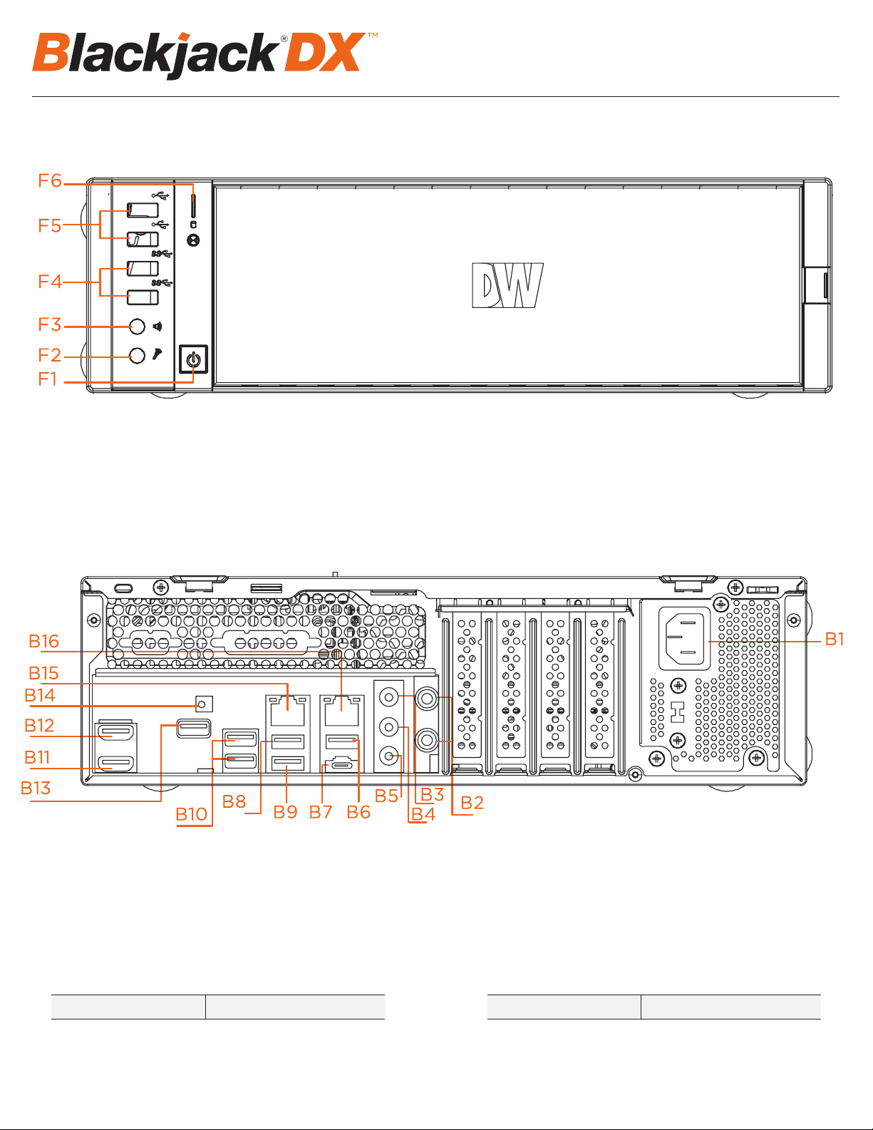
1. Connect a monitor, USB keyboard, USB mouse and network cable to one of the ethernet ports (B8 on the diagram) Configure the camera network first
then will configure local network later.
2. Connect the server to an appropriate power source. Recommend to use UPS system
*recommend to use 3000VA or higher.
3. Turn on the server if the server does not turn on automatically.
(Press the Power Button on the front of the P-RACK. F2 on the diagram).
* Connecting the power cable to the live power source may turn on the serverautomatically
STEP 2: Configure Date and Time
Windows
1. Double click Date and Time icon on the Desktop.
2. Change Time zone if not correct (default is UTC-08:00 Pacific Time)
Press OK after selecting the correct Time zone.
Click Change date and time… to update the date and time if they are not correct.
* Verify the Time zone before updating the date and time. Time may show 2 or 3 hours off due to incorrect Time zone.
(default is UTC-08:00 Pacific Time).
SETTING UP THE E-RACK
STEP 1: Connect Peripherals, power and network
1. Connect a monitor, USB keyboard, USB mouse and network cable to one of the ethernet ports (B8 on the diagram) Configure the camera network first
then will configure local network later.
2. Connect the server to an appropriate power source. Recommend to use UPS system
*recommend to use 3000VA or higher.
3. Turn on the server if the server does not turn on automatically.
(Press the Power Button on the front of the P-RACK. F2 on the diagram).
* Connecting the power cable to the live power source may turn on the serverautomatically
STEP 2: Configure Date and Time
Windows
1. Double click Date and Time icon on the Desktop.
2. Change Time zone if not correct (default is UTC-08:00 Pacific Time)
Press OK after selecting the correct Time zone.
Click Change date and time… to update the date and time if they are not correct.
* Verify the Time zone before updating the date and time. Time may show 2 or 3 hours off due to incorrect Time zone.
3. Press OK after selecting the correct time zone.
4. Click “Change date and time…” to update the date and time if they are not correct.
SETTING UP THE E-RACK
STEP 1: Connect Peripherals, power and network
1. Connect a monitor, USB keyboard, USB mouse and network cable to one of the ethernet ports (B8 on the diagram) Configure the camera network first
then will configure local network later.
2. Connect the server to an appropriate power source. Recommend to use UPS system
*recommend to use 3000VA or higher.
3. Turn on the server if the server does not turn on automatically.
(Press the Power Button on the front of the P-RACK. F2 on the diagram).
* Connecting the power cable to the live power source may turn on the serverautomatically
STEP 2: Configure Date and Time
Windows
1. Double click Date and Time icon on the Desktop.
2. Change Time zone if not correct (default is UTC-08:00 Pacific Time)
Press OK after selecting the correct Time zone.
Click Change date and time… to update the date and time if they are not correct.
* Verify the Time zone before updating the date and time. Time may show 2 or 3 hours off due to incorrect Time zone.
• Verify the time zone before updating the date and time. Time may show 2 or 3 hours o due to an incorrect time zone.
Press OK after adjusting to the correct date and/or time.
4. Press OK to close Date and Time when done.
Linux
1. Update Date and Time by clicking on the time on the upper right-hand corner then click “Time & Date settings…”
2. If the server will be connected to the Internet, leave Set the Time to “Automatically from the Internet” and update the Location to the correct
Time Zone. Enter the nearest major city to select the correct Time Zone. If it shows multiple cities in the list, select the correct city. (e.g.,
New York for EST, Chicago for CST, Denver for MST, and Los Angeles for PST)
5. Press OK after adjusting to the correct date and/or time. Press OK to close the date and time when done.