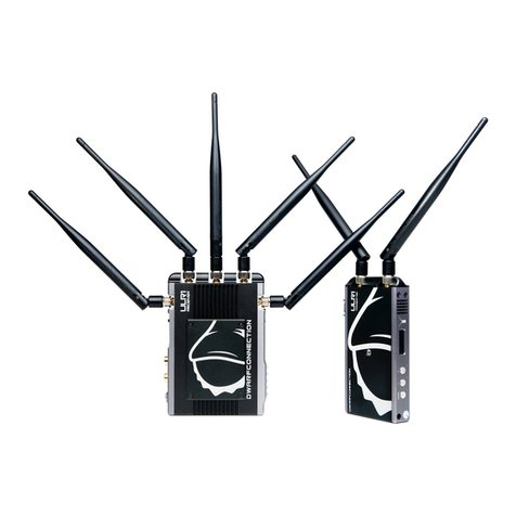
Dwarf Connection DC-LINK-MR1PRO User manual

DC-LINK-MR1PRO
Long-Range Wireless HDMI HD Video Transmission Suite for Indoor and Outdoor Use

2
Manual / Handbuch
Introduction ENGLISH
Congratulations on purchasing the DC-Link-MR1PR Video Transmission System.
Please read this manual carefully before operating your product, and ensure it is kept
in a safe place.
The technology contained in this product, including the device itself as well as
related software and trademarks, is protected by law. Any duplication or
reproduction without the written permission of the copyright owner is prohibited, in
part or in full. All third-party brands or copyrights mentioned in this manual are the
property of their respective owners.
This product has a limited warranty of one year. Warranty may be voided by:
Physical damage to the product
Any damage caused by improper use, maintenance or storage
Damage resulting from the use of incorrect power supplies
Damage not related to the design of the product or the quality of its manufacture
Please follow all instructions to avoid damage to the product or to people.
Please do not open the device. It contains no user-serviceable parts. In the event of
malfunction, please return the device for repair. Any inappropriate use of this
product may lead to the warranty being voided and the manufacturer declining
liability.
Please contact us by email if you have questions or suggestions relating to this
product.

3
Safety Precautions ENGLISH
The Video Transmission System
Do not block or obstruct air vents, as this may cause short circuits, fire or electric
shocks. Turn the device off immediately if it comes into contact with liquids. Please
ensure the transmission system is installed in a stable manner to prevent damage to
the device caused by a fall.
The Power Supply
The device may be used with batteries or AC-DC power supplies of the voltage
specified on the device or in the enclosed documentation.
When using a third-party power adapter, please ensure that the adapter conforms
to the specifications of the device. If batteries are used, please verify that the
batteries are compatible. When using either batteries or external power supplies,
please ensure that the polarity is correct.
Remove the power supply if:
-The device will not be used for an extended period of time
-The power cable is damaged
-The exterior of the device is damaged.
Operating Environments
-Do not place the device on metallic surfaces, to ensure effective data
transfer.
-Do not operate the device in extreme temperatures (operating temperature:
0-40°C)
-Do not use the device in the proximity of water or in high humidity, near
open fires or gas pipes, or near electrical mains.

4
verview ENGLISH
The DC-Link-MR1PR is a high-performance WHDI video transmission system which
transmits uncompressed broadcast-quality video and audio signals up to 150m with
low latency (1ms delay).
The set consists of a transmitter and receiver, each with an HDMI connector. Both
transmitter and receiver have five antennas.
The channel selector button allows the operator to choose between one of ten pre-
programmed frequencies and a dynamic frequency selection (DFS).
The device may be operated using voltages from 7-36V DC and is delivered with a
12V/1A DC power supply.
The device is enclosed in a solid metal casing and can withstand an electrostatic
discharge of ±8kV.

5
Characteristics ENGLISH
HDMI Input & Output
HDMI Standard 1.3
1 0m Range
Transmission ranges of up to 150m are possible with good line-of-sight and optimum antenna
positioning
Real-Time Transmission
With a latency of less than 1ms, the system is suitable for live monitoring applications
Uncompressed Transmission
10-bit, 4:4:4 transmissions via HDMI without format conversion
Supports Formats up to and including 1080p 60Hz
HDCP 1.2 Support
.1/7 Channel Audio Transmission
Embedded audio transmission, including formats such as Dolby True HD, DTS-master etc.
License-free Frequency Band
Functions in the license-free 5GHz ISM frequency range from 5.1-5.9GHz
DFS Function
Using the channel selector, it is possible to switch to the "A" operating mode for DFS
operation. This is mandated for outdoor use in Europe.
RS232 Data Transmission
Channel Selector
10 pre-programmed frequencies may be selected on the device and confirmed without the
need to restart the system. (In Europe, only presets 5&6 are permitted for indoor operation).
Point-to-point Topology
AES-128 Encryption
Variable Input Voltage
Input voltage range from 7-36V DC allows the system to be operated with a variety of
batteries or power supplies
Status Displays
Status displays for DC power, video and RSSI signal strength
Mount
5 1/4" mounts on transmitter and receiver
Plug & Play Design
Ready to use without the need for complex configuration
Mini-USB Socket for Software Updates
Up to ±8kV ESD (Electrostatic Discharge) Protection
Metal Casing
Transmitter and receiver are extremely durable
1 Year Manufacturer’s Guarantee

6
Product Description ENGLISH
Transmitter:
1) Link Status Display: green LED
2) 7-Segment LED-Display for Channel Selection
3) CH Selector Button: 10 Pre-Programmed Frequencies from 1-9 and A for DFS
4) K: Confirmation Button
5) Video Status Display: Yellow LED
6) RS232 Connection
7) Pairing Button
8) Mini-USB Socket
9) HDMI-IN: HDMI Input (Type A)
10) N- FF: Power Switch
11) DC-IN: 7 – 36V DC

7
Product Description
Receiver:
1) RSSI Status Display: Strength of Received Signal (4 blue LEDs)
2) 7-Segment LED-Display for Channel Selector
3) CH Selector Button: 10 Pre-Programmed Frequencies from 1-9 and A for DFS
4) K: Confirmation Button
5) Video Status Display: Yellow LED
6) RS232 Connection
7) Pairing Button
8) Mini-USB Socket
9) HDMI- ut: HDMI utput (Type A)
10) N- FF: Power Switch
11) DC-IN: 7 – 36V DC

8
peration
Transmitter
1. Connect the five omni-directional antennas to the transmitter's RP-SMA male
connectors.
2. There are 5 ¼" 20mm tripod mounts at the base of the transmitter for stable
installation.
3. Connect the enclosed 12V/1A power supply to the DC-IN socket.
4. Connect the HDMI output of your video source (camera, PC etc.) to the HDMI
input of the transmitter.
5. If required, connect the RS232 connector of your source (remote control, PC,
PTZ-camera etc.) to the interface on the transmitter.
6. To ensure compliance with local regulations (see page 11 for more details),
please ensure you select the appropriate frequency or the DFS mode.
Receiver
1. Connect the five omni-directional antennas to the receiver's RP-SMA male
connectors.
2. There are 5 ¼" 20mm tripod mounts at the base of the transmitter for stable
installation.
3. Connect the enclosed 12V/1A power supply to the DC-IN socket.
4. Connect the HDMI output of the receiver to the HDMI input of the display or
recording device.
5. If required, connect the RS232 interface of the receiver to the connector on the
end device (video projector, control panel etc.).
6. Set the receiver to the same frequency as the transmitter.
7. If the transmitter and receiver are not connected in DFS mode, please follow
the instructions on page 14.

9
peration ENGLISH
Antenna Positioning
Position the antennas on the transmitter as shown in the illustration. This ensures the
best possible RF performance.
Install the transmitter and the receiver as high as possible (at least 1.5 metres above
ground level), to maintain a good signal. Please ensure that both transmitter and
receiver are mounted safely to prevent damage to the device.
During operation, try to keep the transmitter and the receiver at similar heights. The
connection is at its strongest when the flat surfaces of the transmitter and receiver
face each other.
Avoid obstacles such as walls, trees, water and steel structures between transmitter
and receiver as much as possible.
Ensure that all the antennas and connections are firmly attached, and that the power
supply conforms to device specifications.
Your system is now ready for use.

10
peration ENGLISH
Establishing a Connection
nce all the other steps have been completed, turn on both devices using the N/ FF
power switch. A connection can only be established if both devices are set to the
same frequency.
If the transmitter detects a video signal, the "Video" LED lights up.
Establishing a connection between the transmitter and the receiver takes between 20
and 30 seconds. During this time, the receiver's video output displays "Link
Connecting...".
nce a connection has been established, the "RSSI" and "VIDE " LEDs on the
receiver light up. The SD disappears and the transmission system is ready for use.
Display
Status
Description
Power
constant
Power supply attached, device turned on
off
No power supply or device turned off
Video
constant
Video input connected and video format recognised
off
Video input inactive or unknown video format

11
peration ENGLISH
Choosing a Frequency
The transmitter and receiver function in the license-free 5.1-5.9 GHz ISM frequency
band. Both include a channel selector button and a 7-segment display to show the
selected frequency. The "A" channel selects the DFS mode, which automatically sets
an available frequency. The positions 0-9 select a pre-programmed frequency without
DFS. Pressing the "CH" button changes the selected channel. The " K" button
confirms the selection.
If multiple systems are used simultaneously, the channels of each system should be
as far from each other as possible to prevent interference and a reduction of the
effective transmission distance. The use of a maximum of four simultaneous systems
is recommended.
Authorised Channels by Country using Manual Frequency Selection without DFS
(Selection)
Position
(Channel)
Frequency
Europe
U.S.A.
Canada
Russia
Japan
China
Turkey
0
5550 MHz
x
x
x
✓
x
x
x
1
5590 MHz
x
x
x
✓
x
x
x
2
5630 MHz
x
x
x
✓
x
x
x
3
5670 MHz
x
x
x
✓
x
x
x
4
5150 MHz
x
x
x
✓
x
x
x
5
5190 MHz
Indoor
Indoor
Indoor
✓
Indoor
✓
Indoor
6
5230 MHz
Indoor
Indoor
Indoor
✓
Indoor
✓
Indoor
7
5270 MHz
x
x
x
✓
x
x
Indoor
8
5310 MHz
x
x
x
✓
x
x
Indoor
9
5510 MHz
x
x
x
✓
x
x
x
Please ensure you are aware of the local regulations regarding radio frequencies in
the relevant country before operating the system.

12
perating Instructions ENGLISH
Pairing Instructions
Pairing is not necessary during normal use.
The transmitter and receiver delivered as a set are pre-configured to work together,
and no other transmitter or receiver can be connected.
Please follow the instructions to establish a new connection among devices from
different sets.
Pairing – Step by Step
a) Please ensure that the transmitter and receiver have been set up correctly. Both
devices must be set to "A" using the channel selector button for pairing
successfully.
When both devices are turned on, the display attached to the video output of the
receiver should show "Select Video Source" or "Searching".
or
b) During this process, the transmitter and receiver should be within 3 metres of
each other.
Press the "Pairing" button on the receiver. The display connected to the receiver
should display "Please Activate Registration on Transmitter Unit".

13
perating Instructions ENGLISH
c) Please press the "Pairing" button on the transmitter. The green link status
display will begin to blink. The display attached to the receiver will show a status
bar and the word "Adding". This status bar will cycle two or three times.
d) nce the process is completed, the display attached to the receiver will show
"Connected to XXXX".
The pairing process is complete, and the receiver and transmitter are connected.
RM

14
perating Instructions ENGLISH
OSD-Menu for Other Pairing Operations
In the event of multiple simultaneous transmissions, it may become necessary to pair
devices using the receiver's SD menu. To access this menu, press and hold the " K"
button for 3-5 seconds. The display connected to the receiver will display the
following:
Press and hold the "Pairing" button for 3-5 seconds to access the setup menu.
"Add new Video Source"
As well as using the pairing method explained above, operators can use this method
to connect new video sources to the receiver. Select this menu option by pressing
"CH". The simultaneous pressing of " K" on the receiver and "Pairing" on the
transmitter allows the devices to connect to each other.
"Remove Video Source"
This option erases previous pairing information, severing the connection between
transmitter and receiver. The menu option can be selected by pressing "CH". When
the " K" button is used to confirm this choice, "Choose Source to Remove" is
displayed.

15
perating Instructions ENGLISH
Confirm that you wish to remove the particular transmitter with the " K" button.
Press " K" again to begin the process.
The transmitter's pairing information is now removed from the list.
"Status"
Displays status information about the radio connection.
"Disconnect Wireless Link"
This indicates that the link between transmitter and receiver has been interrupted.
„Select Uart Baud“
Press the " K" button to set the baud rate for the RS232 data transmission in the
submenu.
Using the "CH" button, choose between 4800, 9600, 19200, 57600 and 115200 Bd.
Confirm selection with " K" button.

16
perating Instructions ENGLISH
RSSI Display
The RSSI (Wireless Received Signal Strength Indicator) display provides information
about the strength of the transmission signal, allowing the operator to monitor the
quality and reliability of the received signal.
Display
Status
Description
RSSI
0-1 LEDs
Radio signal strength is weak and artefacts are visible in the
video signal
2-3 LEDs
Radio signal strength is normal and video quality is good
4 LEDs
Radio signal strength is strong and video quality is very good

17
RS232 Radio Data Transmission ENGLISH
This product includes an RS232 interface on the transmitter and the receiver, allowing
operating instructions to be transmitted wirelessly over significant distances.
The correct baud rate must be selected using the SD menu. The standard value is
115200 Bd, but the devices also support 4800, 9600, 19200 and 57600 Bd.
Connect the RS232 data cable from the control device to the transmitter or receiver as
applicable, and connect the device to be controlled.
If the product has been configured correctly, instructions can be sent wirelessly from
device to device.

18
Transmission Information ENGLISH
The system’s maximum possible range is dependent on each location’s operating
conditions. The stated range of 150 metres cannot always be guaranteed.
Transmission takes place in a non-exclusive bandwidth. As a result, interference from
other devices operating in the 5GHz bandwidth may occur occasionally.
Transmission range may be affected by construction methods or materials used in
surrounding buildings. Environmental conditions such as humidity and the physical
surroundings may have an effect on transmission, irrespective of the transmitter or
receiver.
The strength of the signal is also dependent on the correct positioning of the
antennas, as well as the location, height and angle of the transmitter and the receiver
to each other. If you are unable to achieve a stable transmission, try changing these
factors or choose a different frequency.
When not using the DFS mode, required for outdoor use, the use of this system may
impact other radio systems such as air traffic control or weather radar systems.
DwarfConnection hereby declares that it has informed purchasers of this system of its
legal and appropriate use within the guidelines of the European Telecommunications
Standards Institute (ETSI), and assumes no responsibility for any consequences
resulting from inappropriate use of these devices.

19
Maintenance ENGLISH
Please do not attempt to repair, modify or alter these devices under any
circumstances.
Clean the devices with a soft, clean, dry and lint-free cloth. Do not open the devices,
they contain no user-serviceable parts.
Storage
The devices can be stored at temperatures between -20°C and 60°C. For long-term
storage, please use the original transport case and avoid environmental conditions
such as high humidity, dust, or excessively acidic or base surroundings.

20
Troubleshooting ENGLISH
Possible Cause
Possible Solution
No video output
Lack of power
Check power supplies of transmitter and receiver
and ensure that all cables are connected
correctly and that there is sufficient power
Antennas
Ensure antennas are not damaged and are firmly
connected
Video connection cable
Examine the transmitter’s "Video" LED display. If
the LED is dark, check the HDMI or SDI
connection cable
Frequency selection
Ensure that the transmitter and receiver are set
to the same channel
Unsupported video
format
Check your selected video format against the
product’s technical specifications
Inadequate video
quality
Connections
Check to ensure that all SDI or HDMI cables are
firmly connected
Range is too great or
signal is obstructed
Check how many "RSSI" LEDs are lit on the
receiver. For decent quality, at least 2-3 LEDS
should be lit. If only one is lit, the signal is weak
and the distance between transmitter and
receiver should be reduced. Alternatively,
obstacles between the devices should be
removed or another channel selected
Radio signal is
experiencing interference
Wait one minute, then restart transmitter and
receiver or change the frequency channel
Table of contents
Languages:
Other Dwarf Connection Microphone System manuals