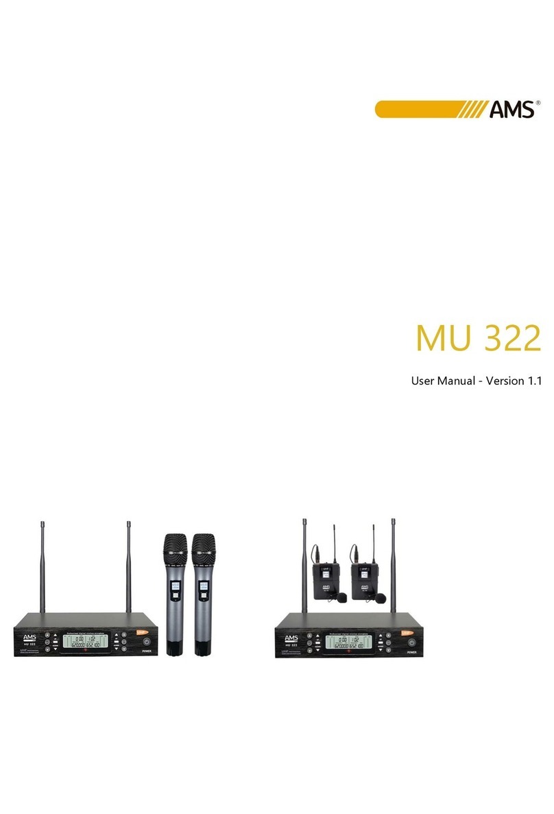
AMS MU 205 Series User manual

MU 205 SERIES
User Manual - Version 1.0

1
SAFETY INSTRUCTIONS
1. Read the instructions of this manual.
2. Keep these instructions in a safe place.
3. Heed all warnings.
4. Follow all instructions.
5. Please, respect your country safety regulations.
6. Don’t use this device close to the water or high humidity places. Clean only with dry cloth.
7. Don’t install near any heat sources such as radiators, heat registers, stoves, or other apparatus (including
amplifiers) that produce heat. Make certain that the equipment is always installed so that is cooled and
can’t overheat.
8. Don’t block any ventilation openings. Install in accordance with the manufacturer’s instructions.
9. Protect the power cord from being walked on or pinched, particularly at plugs, convenience receptacles,
and the point where they exit from the apparatus.
10. Only use attachments/accessories specified by AMS.
11. Unplug this device during lightning storms or when unused for long periods of time.
12. The technical service is required when the device has been damaged in any way, such as power supply
cord or plug is damaged, liquid has been spilled or objects have fallen into the device, doesn’t operate
normally or has been dropped.
13. To completely disconnect this apparatus from the AC mains, disconnect the power supply cord plug
from the AC receptacle.
14. The mains plug of the power supply cord shall remain readily operable.
15. WARNING –to reduce the risk of fire or electric shock, don’t expose this device to rain or humidity.
16. Don’t expose this equipment to dripping or splashing and ensure that no objects filled with liquids,
such as vases, are placed on the equipment.

2
OVERVIEW
MU 205 SERIES
This 2-channel UHF wireless system MU 205 SERIES is a wireless system for the UHF band. It consists of 2
non-Diversity channels. It incorporates 2 transmitters with informative LCD screen. It has independent
volume and display that shows AF, RF and emission frequency levels.
Each channel has a balanced output and a mixed output of both channels.
TECHNICAL DATA:
Frequency Range
500-900MHz
S/N Ratio Response
>100dB
Dynamic Range of Response
>100dB
Modulation Mode
Analog
Stray Radiation
<-60dBc
Working distance
50m
Frequency Response
±40Hz-16KHz
Audio Distorsion
≤0.02%
Working Mode
<100mA
Stability Frecuency
±0.03%
RECEIVER:
Oscilation mode
KT Module
Sensibility Reception
5dBuV
Interferency Relation
>80 dB
Working Voltage
DC12-15V
Working Current
450mA
S/N Ratio Response
>100dB
AC Voltage
100˷240V
BODYPACK TRANSMITTER:
RF Output Power
5mW
Polar Pattern
Unidirectional
Working Current
150mA
Battery Type
2x 1.5V (AA)
Oscilation Mode
KT Module
Type of Transmitter
Dynamic Microfone
Emitter body material
High Quality Plastic
Continuous Using
10˷12 hours

3
HANDHELD TRANSMITTER:
RF Output Power
5mW
Polar Pattern
Unidirectional
Working Current
150mA
Battery Type
2x 1.5V (AA)
Oscilation Mode
KT Module
Type of Transmitter
Dynamic Microfone
Emitter body material
High Quality Plastic
Continuous Using
10˷12 hours
RECEIVER FRONTAL VIEW
1. ON/OFF switch
2. VOLUME CONTROL CHANNEL A
3. RF AND AF LED INDICATOR CHANNEL A
4. A AND B CHANNELS DISPLAY LCD
5. RF AND AF LED INDICATOR CHANNEL B
6. VOLUME CONTROL CHANNEL B

4
RECEIVER REAR VIEW
1. BALANCED OUTPUT CHANNEL A (XLR 3)
2. UNBALANCED MIXED OUTPUT BETWEEN A AND B CHANNELS (JACK ¼”)
3. CHANNEL A ANTENNA
4. DC POWER INPUT (EXTERNAL MAIN SUPPLY)
5. BALANCED OUTPUT CHANNEL B (XLR 3)
6. CHANNEL B ANTENNA
BODYPACK TRANSMITTER
1. ANTENNA
2. THREE-PIN MINI XLR PLUG
3. POWER SWITCH
4. LCD SCREEN DISPLAY
5. BATTERY CASE

5
HANDHELD TRANSMITTER
1. CARTRIDGE
2. LCD SCREEN DISPLAY
3. POWER SWITCH
4. BATTERY CASE
INSTALLATION.
Once the batteries have been inserted into the transmitter and having turned the transmitter switch in ON
position and after having pressed the POWER button on the receiver we will observe that the microphone
is connected when seeing the red RF LED on we will observe that the signal arrives when seeing the green
AF LED flashing.
We can control independently the volume of each of the microphones using the volume controls of the
receiver.

6
INDICACIONES DE SEGURIDAD
1. Lea detenidamente las siguientes instrucciones.
2. Guarde en un lugar seco y seguro este manual.
3. Preste atención a todos los avisos.
4. Siga todas estas instrucciones.
5. Respete las instrucciones de seguridad de su país cuando instale este dispositivo.
6. No use este dispositivo cerca del agua o zonas altamente húmedas. A la hora de limpiarlo, utilice un
paño seco.
7. No instale el dispositivo cerca de ninguna fuente de calor o fuego tales como calefactores, estufas o
incluso amplificadores que produzcan calor. Asegúrese de que una vez instalado el dispositivo, esté en
un lugar fresco y seco.
8. No obstruya ninguna de las salidas. Cuando instale el dispositivo hágalo tal y como lo indican estas
instrucciones.
9. Proteja el cable de alimentación para no ser pisado o pinzado, especialmente en los conectores, tomas
murales y el punto desde donde sale del aparato.
10. Utilice únicamente accesorios especificados por AMS.
11. Desenchufe el dispositivo si no va a ser utilizado durante largos periodos de tiempo.
12. El dispositivo será reparado por el servicio técnico oficial cuando esté dañado, el cable esté deteriorado
o el conector estropeado, si el dispositivo ha sufrido contacto con líquidos o no opera correctamente.
13. Para desconectar totalmente la unidad de la red eléctrica principal, desconecte el cable de la propia
red eléctrica.
14. El conector principal debe poder conectarse y desconectarse de la red eléctrica de manera fácil.
15. ATENCIÓN. Para reducir el riesgo de fuego o shock eléctrico, no exponga este dispositivo a la lluvia o
la humedad.
16. No exponga este equipo a líquidos, gotas, ni salpicaduras, así como evite su ubicación cerca de
recipientes con líquidos.

7
DESCRIPCIÓN GENERAL
MU 150 SERIES
El sistema inalámbrico UHF de 2 canales MU 205 SERIES es un sistema inalámbrico para la banda UHF.
Consta de 2 canales no-Diversity. Incorpora 2 transmisores con pantalla LCD informativa. Dispone de
volumen independiente y pantalla que muestra los niveles AF, RF y frecuencia de emisión. ada canal
dispone de salida balanceada y una salida mezclada de ambos canales.
DATOS TÉCNICOS:
Rango de Frecuencias
500-900MHz
Relación Señal-Ruido
>100dB
Rango Dinámico de Respuesta
>100dB
Modo de Modulación
Analog
Radiación Perdida
<-60dBc
Distancia de Trabajo
50m
Respuesta de Frecuencias
±40Hz-16KHz
Distorsión de Audio
≤0.02%
Modo de Trabajo
<100mA
Estabilidad de Frecuencia
±0.03%
RECEPTOR:
Modo de Oscilación
Módulo KT
Sensibilidad de Recepción
5dBuV
Relación de Interferencia de
Canal
>80 dB
Tensión de Trabajo
DC12-15V
Corriente de Trabajo
450mA
Relación Señal/Ruido
>100dB
Alimentación Corriente Alterna
100˷240V
TRANSMISOR PETACA:
Potencia de Salida
5mW
Directividad
Unidireccional
Corriente de Trabajo
150mA
Alimentación
2x 1.5V (AA)
Modo de Oscilación
Módulo KT
Tipo de Transmisor
Micrófomo Dinámico
Material del Cuerpo del
Transmisor
Plástico de Alta Calidad
Tiempo de Vida de la Batería
10˷12 horas

8
TRANSMISOR DE MANO:
Potencia de Salida
5mW
Directividad
Unidireccional
Corriente de Trabajo
150mA
Alimentación
2x 1.5V (AA)
Modo de Oscilación
Módulo KT
Tipo de Transmisor
Micrófomo Dinámico
Material del Cuerpo del
Transmisor
Plástico de Alta Calidad
Tiempo de Vida de la Batería
10˷12 horas
VISTA FRONTAL RECEPTOR
1. CONMUTADOR ENCENDIDO/APAGADO
2. VOLUMEN CONTROL CANAL A
3. RF AND AF LED INDICATOR CHANNEL A
4. PANTALLA LCD
5. RF AND AF LED INDICATOR CHANNEL B
6. VOLUMEN CONTROL CANAL B

9
VISTA TRASERA RECEPTOR
1. SALIDA BALANCEADA CANAL A (XLR 3)
2. SALIDA DESBALANCEADA MEZCLADA ENTRE CANALES A Y B (JACK ¼”)
3. ANTENA CANAL A
4. ENTRADA ALIMENTACIÓN DC (FUENTE DE ALIMENTACIÓN EXTERNA SUMINISTRADA)
5. SALIDA BALANCEADA CANAL B (XLR 3)
6. ANTENA CANAL B
TRANSMISOR DE PETACA
1. ANTENA
2. CONECTOR MINI XLR 3 PIN
3. CONMUTADOR ENCENDIDO/APAGADO
4. PANTALLA LCD
5. ALOJAMIENTO DE PILAS

10
TRANSMISOR DE MANO
1. CÁPSULA
2. PANTALLA LCD
3. CONMUTADOR ENCENDIDO/APAGADO
4. ALOJAMIENTO DE PILAS
INSTALACIÓN
Una vez introducidas las pilas en el emisor y habiéndose encendido tanto este con el conmutador de
encendido en posición ON como el receptor tras haber pulsado el conmutador de POWER
observaremos que el micrófono está conectado al ver encendido el LED rojo de RF observaremos que
la señal llega al ver destellear el LED verde de AF.
Podemos controlar independientemente el volumen de cada uno de los micrófonos usando los controles
de volumen del receptor.

11
This manual suits for next models
1
Table of contents
Languages:
Other AMS Microphone System manuals
Popular Microphone System manuals by other brands

Audibax
Audibax SM570 user manual

Sennheiser
Sennheiser evolution wireless G3 500 Series instruction manual

schildknecht
schildknecht DATAEAGLE COMPACT 4 Series Installation and commissioning manual

Pyle Pro
Pyle Pro PDWM2300 operating instructions

Manta
Manta MA409 user manual

Altronic
Altronic REDBACK operating instructions