Dwin Plasmaimage HD-250 User manual

Plasmaimage™
HD-242, HD-250
Plasmaimage™
2.4
Printed In USA


1
Table of Contents
Safety Instructions.......................................................................................... 2
Cautions........................................................................................................... 4
Introduction..................................................................................................... 5
Front Panel Controls.......................................................................................6
Processor Rear Panel—Connections and Installation.................................. 7
Programming URC-100 Remote Control to Operate Plasmaimage™....... 11
Quick Reference Remote Control Operation .............................................. 12
Navigating The Control Menus ................................................................... 14
Information Menu..................................................................................... 14
Main Menu ............................................................................................... 14
Input Option. ............................................................................................ 15
Format Option .......................................................................................... 15
Video Control Menu ................................................................................. 16
Setup Menu.............................................................................................. 17
Menu Timeout ................................................................................. 18
Screen Saver.................................................................................... 18
Sidebars ........................................................................................... 18
Num Buttons ................................................................................... 19
Menu Position.................................................................................. 19
Rename Inputs ................................................................................ 19
Rename Formats ............................................................................. 20
Image Setup .................................................................................... 20
Custom Format................................................................................ 22
Relay Setup..................................................................................... 22
Plasmaimage™RS-232 Control ................................................................... 23
Plasma Display Specifications .................................................................... 24
Video Processor Specifications .................................................................. 25
Warranty . ...................................................................................................... 26

2
Safety Instructions
1. Read and apply all of the safety and operating instructions with your
video equipment.
2. Keep all safety and operating instructions for future reference.
3. Unplug this video equipment from the wall outlet before cleaning. Never
use liquid or aerosol cleaners. Use only a damp cloth for cleaning.
4. Do not use any attachments or accessories not recommended by the manu-
facturer as they may cause hazards.
5. Do not use this video equipment near water. Avoid placing it near a bathtub,
kitchen sink, laundry tub, in a wet basement, or near a swimming pool.
6. Do not place this video equipment on an unstable cart, stand, or table. The
video equipment may fall, causing serious injury to a child or adult and serious
damage to the appliance. Use only with a cart or stand recommended by the
manufacturer. Wall or shelf mounting should follow the manufacturer’s in-
structions, and should use a mounting kit approved by the manufacturer.
6.1 Move any appliance and cart combination with care. Quick stops, ex-
cessive force, and uneven surfaces may cause the appliance and a cart to
overturn.
7. Side, Top and Bottom openings in the cabinet are provided for ventilation,
and to insure reliable operation of the video equipment and protect it from
overheating. These openings must not be blocked or covered. Never place
the video equipment on a bed, sofa, rug, or other similar surface that may
block ventilation openings. Never place this product near or over a radiator
or heat register. Do not place this product in a built-in installation such as
a bookcase or rack unless proper ventilation is provided.
8. Operate only from the type of power source indicated on the marking label.
If you are not sure of the type of power supply to your home, consult your
appliance dealer or local power company.
9. This unit is equipped with a three conductor polarized alternating-current
line plug. This plug will fit into the power outlet only one way. This is a safety
feature. If you are unable to insert the plug fully into the outlet, contact your
electrician to replace your obsolete outlet. Do not defeat the safety purpose
of the polarized plug.
10. Route power-supply cords so that they will not be walked on or pinched by
items placed on or against them. Pay particular attention to cords at plugs,
convenience receptacles, and the points where they exit the products.
WARNING
HAZARDOUS VOLTAGE
DO NOT OPEN
ATTENTION
COURANT ELECTRIQUE
NE PAS OUYRIR
CAN SHOCK, BURN OR CAUSE SEVERE INJURY OR DEATH. DO NOT
REMOVE THE TOP COVER. REFER SERVICING TO QUALIFIED PERSONNEL.
!
.

3
11. To protect your video equipment from lightning during a storm or when
it is left unattended and unused for long periods of time, unplug it from
the wall outlet. This will prevent damage to the unit due to lightning and
power-line surges.
12. Do not overload wall outlets and extension cords as this can result in fire
or electric shock.
13. Never push objects of any kind into this video equipment through cabinet
slots as they may touch dangerous voltage points or short out parts that
could results in a fire or electric shock. Never spill liquid of any kind on the
video equipment.
14. Do not attempt to service this unit yourself as opening or removing cover
may expose you to dangerous voltages or other hazards. Refer all servicing to
qualified service personnel.
15. Unplug this video equipment from the wall outlet, and refer servicing to
qualified service personnel under the following conditions:
15.1 When the power cord or plug is damaged or frayed.
15.2 If liquid has been spilled into the video equipment.
15.3 If the video equipment has been exposed to rain or water.
15.4 If the video equipment does not operate normally by following the
operating instructions.
15.5 Adjust only those controls that are covered by the operating instructions
as improper adjustment of other controls may result in damage and
will often require extensive work by a qualified technician to restore
the video equipment to normal operation.
15.6 If the video equipment has been dropped or the cabinet has been
damaged.
15.7 When the video equipment exhibits a distinct change in perfor-
mance.
16. When replacement parts are required, be sure the service technician has
used replacement parts specified by the manufacturer that have the same
characteristics as the original part. Unauthorized substitutions may result
in fire, electric shock, or other hazards.
17. Upon completion of any service or repairs to this video equipment, ask the
service technician to perform routine safety checks to determine that the
system is in safe operating condition.
18. Do not place anything on the video equipment. Heavy objects placed on
any part of this system will cause damage.
19. WARNING: To prevent fire or shock hazard, do not expose this appliance
to rain or moisture. To prevent electric shock do not use this (polarized)
plug with an extension cord, receptacle or other outlet unless the blades
can be fully inserted to prevent blade exposure.
NOTE: This equipment is designed to operate in the USA, Canada and other
countries where the broadcasting system and AC house current is exactly the
same as in the USA and Canada.

4
IMPORTANT INFORMATION FOR THE USER/FCC STATEMENT
This equipment has been tested and found to comply with the limits for a Class
B digital device, pursuant to Part 15 of the FCC Rules. The limits are designed
to provide reasonable protection against harmful interference in a commercial
environment. This equipment generates, uses and can radiate radio frequency
energy and, if not installed and used in accordance with the instructions,
may cause harmful interference to radio communication. However, there is
no guarantee that harmful interference will not occur in a particular installa-
tion. If this equipment does cause harmful interference to radio or television
reception, which can be determined by turning the equipment off and on, the
user is encouraged to try to correct the interference by one or more of the
following measures:
• Reorient or relocate the receiving antenna.
• Increase the separation between the equipment and receiver.
• Connect the equipment into an outlet on a circuit different from that to which
the receiver is connected.
• Consult the dealer or and experienced radio/TV technician for help.
Cautions Regarding Phosphor Burn
DWIN is not responsible for any phosphor burn. Phosphor burn is not covered
by the warranty.
As with all phosphor-based display devices and other plasma displays, plasma
monitors can be susceptible to a condition called phosphor burn under certain
conditions. Phosphor burn describes a condition when latent images remain on
the screen even when the original signal is not displayed. The condition may
occur in any display using phosphors (CRT projectors, direct view monitors,
plasma screens).
The condition is most likely to occur when displaying a static image (e.g.,
news channel, stock market ticker, DVD menu screens, video games) for long
periods of time.
To protect your investment in your DWIN Plasmaimage™, DWIN recommends
the following guidelines to minimize the possibility of phosphor burn:
1. Display only moving images.
2. Avoid displaying fixed images for prolonged periods of time (no more than
five minutes).
3. Display 16:9 (wide screen) video sources.
4. View 4:3 video sources only with the Sidebars option On.
5. Change the position of the menu display from time to time.
6. Always power off your Plasmaimage™when you are finished viewing.
7. Use the DWIN Motion Adaptive™Screen Saver mode and Sidebars option
at all times.

5
Introduction
DWIN’s Plasmaimage™HD system comprises two complementary com-
ponents: DWIN’s acclaimed Digital Video Processor and a high-definition
plasma monitor. The HD-242 plasma display has a native resolution of
1024 x 768 pixels. The HD-250 display has a native resolution of 1366 x 768
pixels. Unless otherwise noted, this manual describes the function of both
plasma models.
The Digital Video Processor consolidates and switches up to 10 video
inputs: two HDCP compliant DVI-D; two RGB; two Component Video; two
S-Video and two composite signals. Six sources support HDTV/digital sig-
nals. The processor provides both source switching and superior digital
video processing of both analog and digital video sources, delivering the
full native resolution of the panel, regardless of the input video source.
This unique separate component design provides flexible connectivity
by allowing the Digital Video Processor to be conveniently located near all
the video sources while the Plasma Display is mounted on a wall or table
top/counter for an ideal viewing position. Only a single cable is needed to
connect the plasma to view up to 10 different video input sources.
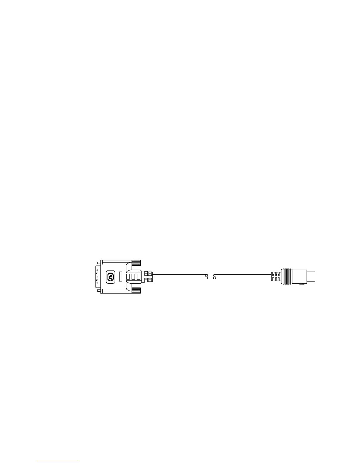
Signal connections between the Digital Video Processor and the Plasma
Display are uncompressed and remain purely digital for optimal picture
quality. The cable includes a bi-directional communication link between
two units used to transmit signals (on, off, display status...) between the
Plasma Display and the Processor. The DVI cable must be connected to
both units to power up1.
The Digital Video Processor is controlled via an infrared (IR) remote that
operates on-screen graphics to select the input source and adjust all picture
controls. The system may also be controlled from the front panel or from
an RS-232 serial port.
The Digital Video Processor automatically senses the video signal type
by measuring both horizontal and vertical scanning frequencies. If the
video signal matches a predefined video source, the Processor then recalls
a predefined setting from the system’s memory. Predefined video sources
include: 480i, 480p, 580i, 580p, 1080i, 540p, and 720p. A variety of computer
sources are also supported including: VGA, SVGA, XGA and SXGA.
Settings for each input video signal can then be adjusted and stored
separately in the system’s memory. These settings are automatically recalled
for each input and video type when selected.
Two programmable +12 Volt DC outputs are also provided to trigger
relay-activated electronic devices.
1. Please note: All functions for the Plasmaimage™HD Series (including on/off) are automati-
cally controlled via the separate Digital Video Processor or remote control. As a result, all
non-DVI inputs and control buttons (located on the front panel) are disabled in HD-Series
display.

6
Processor Front Panel Controls
The Plasmaimage™Processor front panel controls include:
• A POWER button to turn the system On or Off.
• An indicator light (LED) which is lit when the unit is turned on and blinks when
a valid IR command is received.
— When the LED is dark the AC power to the unit is turned off.
— When the LED is flashing, power is connected and the unit is in the standby
mode.
•An IR Receiver Window
• A MENU button to display the Main menu or to return to the previous
menu.
•
Up ▲or down ▼FUNCTION buttons to sequences through the on-screen
menu options.
•
Left ◀or right ▶VALUE buttons to adjust values or to move to a sub-menu.
Plasma Display Front Panel Controls
Please note: All functions for the Plasmaimage™HD Series (including on/off)
are automatically controlled via the separate Digital Video Processor or remote
control. As a result, all non-DVI inputs and control buttons (located on the
front panel) are disabled in HD-Series plasma displays.
• To power up the plasma display, the DVI cable MUST first be connected to
the Digital Video Processor.
• The plasma display has a master power switch, located next to the AC Power
input.
• After connecting both the AC power and DVI cable, turn the master power
switch to place the plasma display in standby mode
— When the LED is DARK the AC plug is not connected or the master power
switch is off.
— When the LED is Amber, the plasma display is in standby mode.
— When the LED is GREEN, the display is ON.

7
Processor Rear Panel — Connections and Installation
1 9
2
3
5
6
7
8
4
1. DVI/HDCP Output to Display DVI-D
2. DVI/HDCP Inputs (DVI 1, DVI 2) DVI-D
3. Switched +12 VDC Outputs (RY1, RY2) 2.5mm DC Plug
4. RGBS Computer/HDTV Inputs (RGB1, RGB2) D-sub 15 pin Socket
5. RS-232 Computer Input (RS-232) D-sub 9 pin Socket
6. S-Video Inputs (S1, S2) 4 pin Mini-Din
7. Composite Video Inputs (V1, V2) RCA Type
8. Component Video Inputs (Y1, R1, B1) RCA Type
(Y2, R2, B2) RCA Type
9. AC Power Receptacle (AC IN) 3 Prong Receptacle

8
1. DIGITAL OUTPUT (DVI Cable)
Connect the digital output of the Digital Video Processor to the display using
a high-quality DVI-D cable. The DVI cable must be connected to both compo-
nents (processor and plasma display) to power up.
For the HD-242 plasma display, use a DVI cable with DVI-male connectors
on both ends of the cable .
For the HD-250 display, use a DVI cable with a DVI-male and HDMI connec-
tor. Connect the DVI-male connector to the processor and the HDMI connector
to the plasma display.
If you are using third-party DVI cables, DWIN recommends testing for noise
and signal quality prior to final installation.
DVI cables are delicate. They require careful handling to ensure proper
operation. During installation, do not pull on the cable with excessive force.
Do not drop the DVI connectors. The shell can be easily damaged.
Special Note about In-Wall Installation or Cable Lengths Longer Than 25 Feet:
A standard rectangular DVI connector is fairly large in size (approximately 2”
wide) making it difficult to run through the walls. DWIN’s solution is to termi-
nate one end of the DVI cable with a .75” circular connector that can easily run
through a 1” conduit (figure 1).
DWIN offers DVI cables in three lengths: 25, 35, and 50 feet. Part numbers for
these cables are DVI-R-xx, the “xx” refers to the length of the cable. To extend
the cable length up to 100 feet, use DWIN’s Cable Extender.
To convert from Circular connector back to DVI-D connector for the HD-242,
DWIN offers 2 foot Circular to DVI-D Adapter.
To convert from Circular connector back to HDMI connector for the HD-250,
DWIN offers 2 foot Circular to HDMI Adapter.
DWIN recommends first connecting this 2-foot adaptor and power cable
prior to wall mounting the display.
Fig. 1: DVI Cable with Circular Connector
2. DVI-D INPUTS
The DVI 1 and DVI 2 inputs are HDCP compliant for High-Definition (480p, 540p,
580p, 720p, 1080i) sources or computer graphics with VGA, SVGA, XGA, and
WXGA resolutions. For computer graphics with VGA, SVGA, XGA, or WXGA
it is recommended to set the computer to 60 Hz vertical scanning frequency.
If your computer video card has DVI output, connect the DVI cable to the DVI

9
1 or DVI 2 inputs of the Digital Processor. Select the corresponding DVI input by
pressing “9” or “0” on the remote control, then activate the DVI output from
the computer by using computer’s display set-up menu.
Pin No. Signal Name Pin No. Signal Name Pin No. Signal Name
1 Data 2- 10 Data 1+ 18 Data 0+
2 Data 2+ 11 Data 1 / Shield 19 Data 0 / Shield
3 Data 2 / Shield 14 +5V Power 22 Clock Shield
6 DDC Clock 15 Ground 23 Clock+
7 DDC Data 16 Hot Plug Detect 24 Clock-
9 Data 1- 17 Data 0-
The following are the pin assignments for the DVI-D connectors:
Pin No. Signal Name Pin No. Signal Name Pin No. Signal Name
1Red 6 Ground 11
2 Green 7 Ground 12
3 Blue 8 Ground 13 Horz. SYNC
4 9 Ground 14 Vert. SYNC
5 10 15
The following are the pin assignments for the D-sub 15 pin connector:
5. RS-232 COMPUTER INPUT
The RS-232C serial interface is provided for external control of the Plasmaim-
age™from a central controller, such as a Home Theater control computer, Smart
Home automation system, etc.
For D-sub 9 pin connector pin-out and RS-232 command list, please refer
to “Plasmaimage™RS-232 Control” section.
6. S-VIDEO INPUTS (S1, S2)
The S1 and S2 inputs are provided for NTSC (480i) or PAL (580i) video sources,
such as off-air tuners, satellite systems, cable boxes, SVHS VCR and DVD play-
ers. S-Video inputs, instead of composite video inputs, are recommended for
use with DVD players and satellite systems.

10
7. COMPOSITE VIDEO INPUTS (V1, V2)
The V1 and V2 inputs are provided for NTSC (480i) or PAL (580i) video sources,
such as off-air tuners, satellite systems, cable boxes, VCR and DVD players.
8. COMPONENT VIDEO INPUTS (Y1, Y2, Y3)
Two component video Y, Cr, Cb or Y, Pr, Pb inputs are provided for interlaced
and non-interlaced component video signals from regular DVD players (480i,
580i), progressive component video signals from progressive DVD players
(480p, 580p), and progressive or interlaced HD signals (480p, 540p, 720p,
1080i) from HD sources. The Plasmaimage™Processor automatically detects
the resolution and configuration of the component video signal applied to its
input and processes it accordingly.
9. AC POWER RECEPTACLE
The AC power receptacle should be connected to a non-switched 120 VAC outlet
using the power cord provided with the Plasmaimage™HD system.
DWIN strongly recommends that the Plasmaimage™Display and Processor
be connected to the same AC circuit.

11
Programming URC-100 Remote Control
to Operate the Plasmaimage™ Processor
The Plasmaimage™System is shipped with a factory pre-programmed remote
control.
1. Press the TV device button.
2. Press and hold both the SHIFT and ENTER buttons for 3 seconds. The display
will blink “Set” and then “DWIN.”
3. Enter the Plasmaimage™brand code: 257.
4. Press the LIGHT button on the right hand side to complete the programming.
To operate other audio and video devices refer to the URC-100 Operating
Manual.

12
1 2 3
4 5 6
7 8 9
+10 0 ENT
MODE SUB CTR REAR
=
SELECT
AUD CD DVD AUX
SAT
MUTE
MENU EXIT
GUIDE INFO
PREV
CH
TV
VCR
OFF
TV VCR
SHIFT
CBL LIGHT
DWIN
ON
VOL CH
Quick Reference Remote Control Operation

13
The remote control provided with the Plasmaimage™is a universal remote
control capable of controlling 8 different devices.
1.Select TV device to control the Plasmaimage™Processor.
2. Press ON to turn the Plasmaimage™ON.
3. Press OFF to turn the Plasmaimage™OFF.
4. Press VOLUME up ▲or down ▼to adjust the volume.
5. Press MUTE to turn the sound off.
6. Press MENU to display the Main menu or to return to the previous menu.
7. Use the numbered buttons for direct switching of inputs.
To select a specific input, press a numbered button.
8. Press up ▲or down ▼to sequence through the on-screen menu options.
9. Press left ◀or right ▶to adjust values or to navigate to a sub-menu.
10. Press SEL to advance to a sub-menu.
11. Press EXIT to clear the on-screen menus.
12. Press ENTER to perform a selected function.
13. Press INFO to display the system status.
14. Press GUIDE to sequence through format options. Or press CTR up ▲
followed by a numbered buttons 1-4 to select format.
The brand code for Plasmaimage™is 257.
For Press
Composite Video Inputs 1or 2
S-Video Inputs 3or 4
Component Inputs 5or 6
RGB Inputs 7or 8
DVI Inputs 9or 0
Numeric Button Standard Format HD Format
1 Standard HD
2 Anamorphic Custom
3 Letterbox
4 Custom

14
Navigating the Control Menus
Information Menu
The Information menu reports the current status for input video source, image
format and input video type. The Information menu may be accessed when no
other menu is displayed on the screen.
1. To display the Information menu, press INFO button on the remote control.
2. Press EXIT on the remote to clear the screen immediately.
Main Menu
The Main menu offers a choice of Input selection or Format selection, and
navigation options to Video controls and Setup functions.
1. Press MENU to display the Main menu.
2. Scroll up ▲or down ▼the list to highlight the desired option.
3. Press left ◀or right ▶to move adjust values or navigate to a sub-menu.
4. Press EXIT on the remote to clear the screen immediately.
The Time Out feature will automatically clear the screen unless another button
on the remote or front panel is pressed.
Information
Input DVI 1
Format HD
Video Type 720p
DWIN Plasmaimage™
Input DVI 1
Format HD
Video
Setup

15
Input Option
All 10 video inputs may be selected either directly or through Input menu. To
select a video input directly, press the numeric buttons on the remote control
that corresponds to the desired input:
• For composite video inputs, press 1or 2
• For S-Video inputs, press 3or 4
• For component video inputs, press 5, or 6
• For RGB inputs, press 7or 8
• For DVI inputs, press 9or 0
To select a video input through the menu:
1. From the Main menu scroll up ▲or down ▼to highlight the Input option.
2.Use the up ▲or down ▼button to sequentially select the input sources. Or
while the Input option is highlighted use the numbered buttons 1through 0
on the remote control for direct switching of inputs.
Format Option
Format refers to the aspect ratio of the original video recording. For example, a
DVD player which is connected to the component input may be used to playback
either Standard (4:3) format or Letterbox format. Standard, Anamorphic and
Letterbox formats are available for 480i, 480p, 580i and 580p video sources. HD
(16:9) format is available for 540p, 720p and 1080i video sources. In addition
to predefined formats, a Custom format selection is provided.
To adjust the custom format, see the Custom Format section in the Setup
menu instructions.
Numeric Button Input
1 Video 1 (composite)
2 Video 2 (composite)
3 S-Video 1
4 S-Video 2
5 Component 1
6 Component 2
7 RGB1
8 RGB2
9 DVI 1
0 DVI 2
Numeric Button Standard Format HD Format
1 Standard HD
2 Anamorphic Custom
3 Letterbox
4 Custom
DWIN Plasmaimage™
Input Video 1
Format Standard
Video
Setup

16
Format Option Continued
1. From the Main menu scroll up ▲or down ▼to highlight the Format option.
This enables you to select the aspect ratio.
2. Use the left ◀or right ▶button to sequentially select the aspect ratio. Or use
buttons 1, 2, 3 or 4on the remote control for direct selection of Formats.
3. To access the Format option directly (bypassing the Main menu), press the
GUIDE button quickly followed by the corresponding format number but-
ton: 1, 2, 3 or 4.
Format settings for each video input are stored separately in the system’s memory.
These settings are recalled for each input and video type when selected.
Video Control Menu
1. For direct access to the Video Control menu, press either the up ▲or
down ▼button on the remote or the Digital Video Processor.
You can also navigate to the Video Control menu from the Main menu by
scrolling up ▲or down ▼to highlight the Video option. Use the left ◀or
right ▶button to advance to the Video Control menu.
2. Use the up▲or down▼button to select the desired video control option.
3. Use the left ◀or right ▶button to adjust video settings.
Once you press the left ◀or right ▶button, this menu will be replaced with
a single line display at the bottom of the screen. This allows you to see the
picture while adjusting the control settings.
DWIN Plasmaimage™
Input Video 1
Format Standard
Video
Setup
Contrast 50
Video Controls
Contrast 50
Brightness 50
Color 50
Tint 50
Sharpness 5
Gamma 4
Color Temp Mid

17
4. To restore the full menu, press MENU or up ▲or down ▼button.
Picture setting changes made with the Video menu are saved in memory for
each of the ten video inputs. Many video sources are different enough to re-
quire this fine-adjusting and these settings will be recalled each time a video
input is selected.
Gamma
Gamma is a non-linear function applied to the video source signal in order to
enhance picture quality especially in shadow details. Plasmaimage™provides four
gamma selections to compensate for various ambient lighting conditions.
1. Select the gamma option that shows the best shadow detail.
Color Temp
This feature selects plasma display’s color temperature to allow you to adjust
the picture to suit your viewing tastes and environment. The Plasmaimage™HD
is factory preset for MID color temperature to display the most natural colors.
HIGH color temperature results in a brighter image, which may be appropriate
for brightly lit rooms. Low and Mid-Low temperature settings result in slightly
darker images with more subtle colors.
1. Use the left ◀or right ▶buttons to select Low, Mid-Low, Mid or High color
temperature.
Setup Menu
1. From the Main menu scroll up ▲or down ▼to highlight the Setup option.
2. Use the left ◀or right ▶button to advance to the Setup Options menu.
Setup Options
Menu Timeout 30 sec
Screen Saver On
Sidebars On
Num Buttons Input
Menu Position
Rename Inputs
Rename Formats
Image Setup
Custom Format
Relay Setup

18
Menu Timeout
This feature selects the length of time before the on-screen menus disappear
from the screen.
1. Use the left ◀or right ▶button to select 15, 30, 45 or 60 seconds.
Motion Adaptive™Screen Saver
Motion Adaptive™Screen Saver is an exclusive DWIN feature designed to
reduce the potential of phosphor burn when static images are displayed. The
Motion Adaptive™Screen Saver circuit continually monitors the video image
for motion. When a static image is displayed for more than 2 minutes, the Plas-
maimage™displays a moving screen saver menu. If the video signal remains
static for 5 minutes, the system will shut down.
1. To exit the Screen Saver menu, press any key on the remote.
2. To activate the Screen Saver function, use the left ◀or right ▶button to
turn the Screen Saver function On or Off.
NOTE: DWIN strongly recommends that the Screen Saver function remain
ON at all times.
NOTE: The Motion Adaptive™Screen Saver can not prevent phosphor burn
if only a partially static image is displayed .
Sidebars
This feature is designed to reduce the potential for phosphor burn when viewing
video sources with 4:3 aspect ratio. When this function is on, the Plasmaim-
age™will display a gray sidebar on both sides of the picture.
1. To activate the Sidebar function use the left ◀or right ▶button to select
On or Off.
This feature works for 480i, 580i, 480p, 580p and computer graphic video
sources.
For HD video sources that display a 4:3 aspect ratio programs, please refer to
your HD tuner manual to activate the gray side-bar option.
NOTE: DWIN strongly recommends that the Sidebars option remain ON at
all times.
DWIN Plasmaimage™
Input Video 1
Screen Saver
This manual suits for next models
1
Table of contents
Other Dwin Monitor manuals