dymax BlueWave 75 User manual

Dymax BlueWave®75 Rev. 2.0 User Guide
UV Light-Curing Spot Lamp
■Instructions for Safe Use
■Setup and Operation
■Maintenance
■Ordering Spare Parts and Accessories
System Discontinued 1/1/2018

2
Dymax BlueWave® 75 User Guide
About Dymax
UV/Visible light-curable adhesives. Systems for light curing, fluid dispensing, and fluid packaging.
Dymax manufactures industrial adhesives, light-curable adhesives, epoxy resins, cyanoacrylates, and activator-cured adhesives.
We also manufacture a complete line of manual fluid dispensing systems, automatic fluid dispensing systems, and light-curing systems.
Light-curing systems include LED light sources, spot, flood, and conveyor systems designed for compatibility and high performance
with Dymax adhesives.
Dymax adhesives and light-curing systems optimize the speed of automated assembly, allow for 100% in-line inspection, and increase
throughput. System designs enable stand-alone configuration or integration into your existing assembly line.
Please note that most dispensing and curing system applications are unique. Dymax does not warrant the fitness of the product for the
intended application. Any warranty applicable to the product, its application and use is strictly limited to that contained in the Dymax
standard Conditions of Sale. Dymax recommends that any intended application be evaluated and tested by the user to insure that desired
performance criteria are satisfied. Dymax is willing to assist users in their performance testing and evaluation by offering equipment trial
rental and leasing programs to assist in such testing and evaluations. Data sheets are available for valve controllers or pressure pots upon
request.

3
Dymax BlueWave® 75 User Guide
Contents
Introduction................................................................................................................................................ 4
Where to Get Help .......................................................................................................................................................... 4
Safety.......................................................................................................................................................... 4
UV Light-Curing System Safety Considerations ............................................................................................................... 6
Product Overview........................................................................................................................................ 8
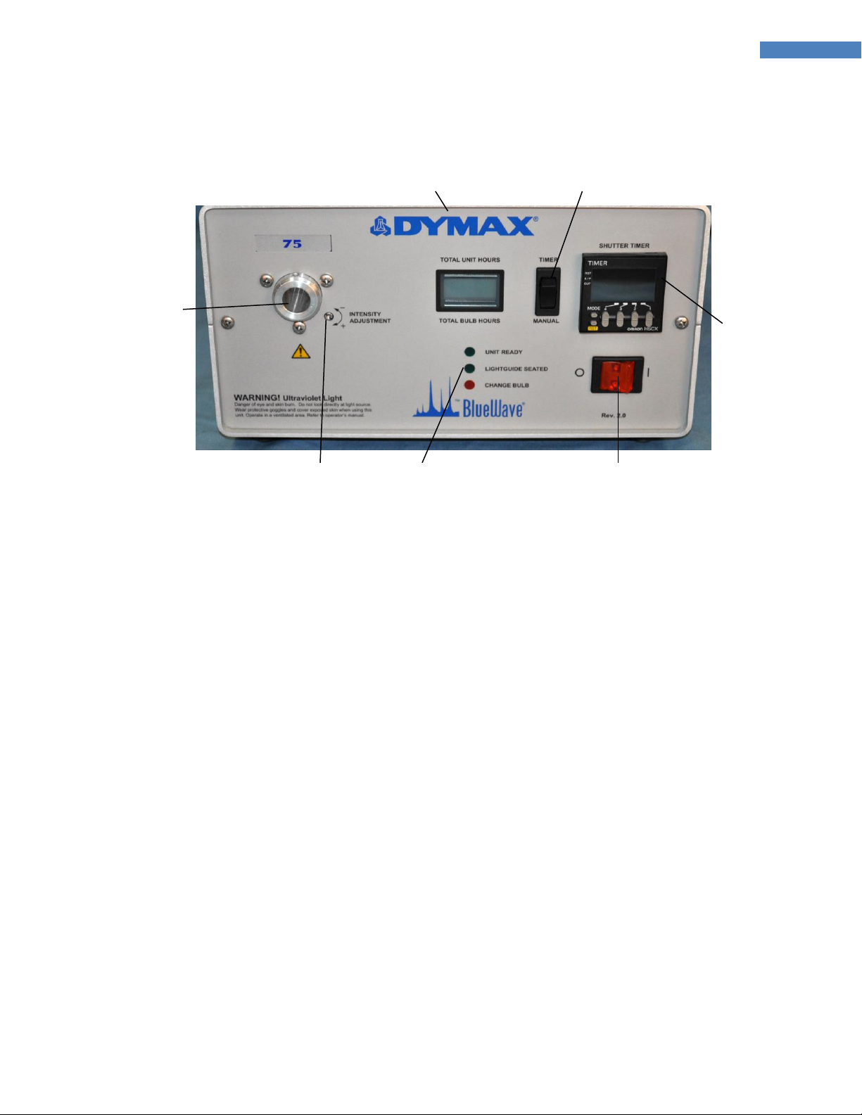
Description of the BlueWave 75...................................................................................................................................... 8
Assembly and Setup .................................................................................................................................... 9
Unpacking and Inspecting Your Shipment....................................................................................................................... 9
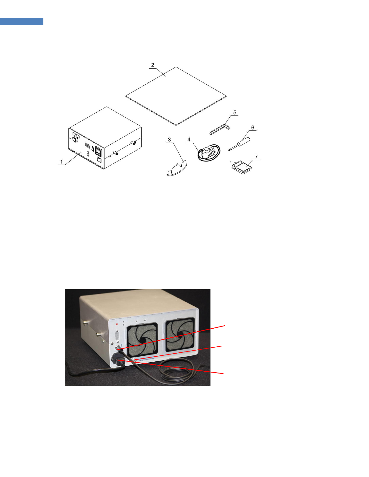
Parts Included with the BlueWave 75 ............................................................................................................................. 9
Installation and System Interconnect..........................................................................................................10
Settings and Adjustments...........................................................................................................................12
Intensity Adjustment..................................................................................................................................................... 12
Intensity Validation ....................................................................................................................................................... 12
Intensity Control............................................................................................................................................................ 12
Setting the Cycle Duration............................................................................................................................................. 13
Lamp Dual-Hour Meter.................................................................................................................................................. 14
System Operation.......................................................................................................................................15
Maintenance..............................................................................................................................................16
Lightguide Maintenance................................................................................................................................................ 16
Fuse Replacement ......................................................................................................................................................... 16
Fan Filter Maintenance.................................................................................................................................................. 16
Bulb Replacement ......................................................................................................................................................... 17
Troubleshooting.........................................................................................................................................19
Frequently Asked Questions.......................................................................................................................20
Spare Parts and Accessories........................................................................................................................22
Spare/Replacement Parts.............................................................................................................................................. 22
Options/Accessories...................................................................................................................................................... 23
Specifications.............................................................................................................................................24
Specifications................................................................................................................................................................. 24
Definition of Terms ....................................................................................................................................25
Warranty....................................................................................................................................................26
Replacement Bulb Warranty ......................................................................................................................................... 26
Index..........................................................................................................................................................27

4
Dymax BlueWave® 75 User Guide
Introduction
The enclosed BlueWave 75 UV Light-Curing Spot Lamp System was developed and manufactured by the
Dymax team, driven by a desire to best serve your needs. Before shipping, your BlueWave 75 was thoroughly
checked and tested for trouble-free performance.
The proper setup and operation of this system will maximize safety and user-friendly performance, providing
optimum yield of your technological process.
Therefore, we encourage you to read, understand, and follow all safety and operating instructions and
recommendations compiled in this and other related manuals prior to setting up and operating this new
spot-lamp system or its individual components.
If you encounter a problem, have any questions, or would like to pass on your suggestions or
recommendations, please contact our Application Engineering or Customer Service Departments. Trained
Dymax professionals are standing by to serve you.
Par conséquent, nous vous encouragez a lire, comprend, et suivre tout sécurité et instructions d’opération
et conseillations rédiger dans cette et autre manuels établir un lien avant de mettre en place et de faire
marcher cette nouveau système de lampe de tache ou cette composants individuel.
Si vous rencontrez un problème, avait n’importe de questions, ou si vous voudrez de nous aider avec tes
suggestions ou conseillations, s’il vous plait contacte notre départements technique ou service client. Dymax
formé professionnels attendre à vous servir.
Where to Get Help
Dymax Customer Support and Application Engineering teams are available in the United States, Monday
through Friday, from 8:00 a.m. to 5:30 p.m. Eastern Standard Time. You can also email Dymax at
[email protected]. Contact information for additional Dymax locations can be found on the back cover of this
user guide.
Additional resources are available to ensure a trouble-free experience with our products:
◼Detailed product information on www.dymax.com
◼Dymax adhesive Product Data Sheets (PDS) on our website
◼Material Safety Data Sheets (MSDS) provided with shipments of Dymax adhesives
Safety
CAUTION! Always wear proper eye protection when working with this unit, which emits high-
intensity ultraviolet and visible energy! Note: The rear of the unit also emits stray UV & Visible
energy.
WARNING! Always observe safety requirements!
CAUTION! Risk of electrical shock if cover is removed!

5
Dymax BlueWave® 75 User Guide
CAUTION! Cover is warm to the touch when unit is in operation!
To use this system safely, it must be set up and operated in accordance with the instructions given by Dymax.
The system’s design was developed to maximize operator safety and minimize exposure to UV. Using the
system in any other manner will impair the protection of the system. Dymax assumes no liability for any
changes that may impair the protection of the system.
Safety Recommendations
◼Use the provided safety eyewear or an approved face shield for eye/face protection.
◼Long-sleeved shirts or a lab coat are recommended to protect arms and the use of UV opaque gloves will
protect the hands.
NOTE: The BlueWave 75 emits UVA and visible light. Never look directly into the lightguide entrance fitting or
end of lightguide while the unit is on.
Sécurité
PRÉ-CAUTION! Toujours faisez de l’usage des lunettes de protection ou protéger de visage
marche près du devant d’élément!
AVERTISSEMENT! Remmarquez toujours besoin de sécurité!
PRÉ-CAUTION! Risque de décharge électrique quand le couvert est enlever!
PRÉ-CAUTION! Le couvert est chaud a le touche quand l’élément est en opération!
L’équipment ètre concu pour ètre utilisé correctement constituer, avec composants brancher correctement,
et marché en conformément avec instructions important. Le plan étais developer pour render au maxime
opérateur sécurité et minimiser expositon à ultraviolette.
Recommander de Sécurité
◼Emploi lunettes, ou un protéger de visage pour protection de ultraviolet pour protéger vous oeux.
◼Chemises à manche long, ou manteau de labo, sont recommander pour protéger les bras, et utilisation de
ultraviolette gants opague vais protéger les mains.
REMARQUER: Avec le filtre intérieur installé, l’onde bleu émettre lumière. Ne jamais regardez directement à la
source de lumière pendant que l’élément est en opération.
Sicherheitshinweise
ACHTUNG! Tragen Sie immer eine Sicherheitsbrille oder einen Gesichtsschutz, wenn Sie nahe an
der UV Lichtquelle arbeiten. Die Rückseite des Gerätes emittiert gestreutes UV Licht!
WARNHINWEIS! Bitte beachten Sie immer die Sicherheitshinweise!

6
Dymax BlueWave® 75 User Guide
ACHTUNG! Gefahr eines Stromschlages bei geöffnetem Gehäuse!
ACHTUNG! Gehäuse erwärmt sich während des Betriebs: Vorsicht bei Berührung!
Dieses Gerät wurde so entwickelt, dass es nur vollständig, alle Komponenten korrekt miteinander verbunden,
in Übereinstimmung mit relevanten Instruktionen betrieben wird. Bei der Entwicklung wurde weiterhin
großen Wert auf die Benutzersicherheit und minimale UV Belastung gelegt.
Sicherheitshinweise
◼Tragen Sie immer die mitgelieferten Sicherheitsbrille oder speziellen Gesichtsschutz, der Ihre Augen vor
UV Licht schützt.
◼Wir empfehlen Langarm - Hemden oder einen Laborkittel zu tragen, um die Arme zu schützen. Für die
Hände empfehlen wir UV- geblockte Handschuhe.
BITTE BEACHTEN SIE: Durch den installierten inneren Filter strahlt die BlueWave 75 und sichtbares Licht aus.
Schauen Sie deshalb niemals direkt in die Lichtquelle, wenn das Gerät angeschaltet ist.
UV Light-Curing System Safety Considerations
Dymax light-curing technology has been used successfully for over 30 years. The fast cure, one-component
nature of our curing technology has made it the process of choice for many manufacturers requiring a “cure
on demand” assembly process. There are four common questions/concerns related to light-curing systems:
UV exposure, high-temperature surfaces, ozone, and bright, visible light.
UV Exposure
Standard Dymax UV light-curing systems have been designed to primarily emit UVA light (Figure 1). UVA light
is generally considered the safest of the three UV ranges: UVA, UVB, and UVC. Although OSHA does not
currently regulate ultraviolet-light exposure in the workplace, the American Conference of Governmental
Industrial Hygienists (ACGIH) does recommend Threshold Limit Values (TLV‘s) for ultraviolet light. The strictest
interpretation of the TLV (over the UVA range) for workers’ eyes and skin is 1 mW/cm2(intensity), continuous
exposure. Unless workers are placing bare hands into the curing area, it is unusual to exceed these limits. To
put 1 mW/cm2limit into perspective, cloudless summer days in Connecticut regularly exceed 3 mW/cm2of
UVA light and which includes the more dangerous UVB light, primarily responsible for sun tans, sun burns, and
skin cancer.
The human eye cannot detect “pure” UV light, only visible light. A radiometer should be used to measure
stray UV light to confirm the safety of a UV-curing process. A workstation that exposes an operator to more
than 1 mW/cm2of UVA continuously should be redesigned.
Light-curing technology can be a regulatory compliant, “worker-friendly” manufacturing process when the
proper safety equipment and operator training is utilized. There are two ways to protect operators from UV
exposure: shield the operator and/or shield the source.

7
Dymax BlueWave® 75 User Guide
Figure 1. Spectrum of Light
Shield the Operator
UV-Blocking Eye Protection –UV-blocking eye protection is recommended when operating UV-curing
systems. Both clear and tinted UV-blocking eye protection is available from Dymax.
UV-Blocking Skin Protection –Where the potential exists for UV exposure upon skin, opaque, UV-blocking
clothing, gloves, and full-face shields are recommended.
Shield the Source of UV Light
Any substrate that blocks UV light can be used as a shield to protect workers from stray UV light. The
following materials can be used to create simple shielding structures:
Sheet Metal –Aluminum, steel, stainless steel, etc. Sheet metal should be coated black or black anodized to
minimize reflection of UV and visible light toward operators.
Rigid Plastic Film –Transparent or translucent, UV-blocking plastics (typically polycarbonate or acrylic) are
commonly used to create shielding where some level of transparency is also desired.
Flexible Film –Translucent UV-blocking, flexible urethane films can be used to quickly create workstation
shielding. This UV-blocking, flexible urethane film is available from Dymax.
High-Temperature Surfaces
Surfaces exposed to high-intensity curing lights will rise in temperature. The intensity, distance, exposure
time, cooling fans, and the type/color of the surface can all affect the actual rise in surface temperature. In
some cases, exposed surfaces can reach temperatures capable of producing a burn or causing damage to a
substrate. In these cases, care must be taken to ensure either a more moderate surface temperature or
appropriate protection/training for operators.
Ozone
Standard Dymax bulbs (UVA type) generate an insignificant amount of UVC and therefore essentially no
ozone. Some UV light-curing systems, like those used to cure UV inks, emit primarily “shortwave” (UVB and
UVC) energy. Upon exposure to UVC energy (specifically <240 nm), oxygen molecules (O2) split into oxygen

8
Dymax BlueWave® 75 User Guide
atoms (O) and recombine with O2to create ozone O3. The current, long-term ozone concentration limit
recommended by ACGIH, NIOSH, and OSHA is 0.1 ppm (0.2mg/m3).
Bright, Visible Light
The bright, visible light energy emitted by curing systems can cause eyestrain if proper eye protection or
shielding is not used. Tinted eye protection and/or opaque/tinted shielding can be utilized to address this
concern.
Summary
UV-light sources can be more “worker friendly” than many commonly accepted industrial processes, provided
the potential concerns are addressed. Both the lower working temperature and lack of spurious frequency
transmission that this system produces make it even more user friendly. Contact your Dymax representative
for information regarding the proper use of Dymax light-curing systems.
Product Overview
Description of the BlueWave 75
The BlueWave 75 is a high-intensity, UV light-curing spot lamp used for the curing of adhesives, coatings, and
potting materials. It emits UV light from a lightguide which can be hand-held for complete mobility, fixtured
into position for repetitive operations, or integrated into automated equipment.
The unit consists of an anodized aluminum housing, containing an electronic power supply, circuit protection,
a bulb/reflector assembly, an internal light filter, a thermostatically-controlled cooling fan, a lightguide mount,
bulb and unit status indicator lights, a combination resettable and non-resettable hour-meter, and a shutter
system. A thermal shutdown sensor is provided for internal temperature control of the unit. A cover-closed
switch and lightguide-sensing switch add to the safety of the unit. Fan filters should be changed or cleaned
frequently to prevent blockage and reduced ventilation airflow. Electric shutters are supplied with timed and
manual shutter operating modes. The lightguide is separate and plugs into the lightguide entrance fitting on
the front panel (the forward facing lightguide mount).
An intensity control feature allows operators to adjust output intensity during process validation and
production. Users can now manually adjust intensity to compensate for bulb degradation and to maintain an
optimized output or allow it to emit direct line of sight energy to unprotected personnel.
CAUTION: Once the lightguide is engaged there exists the possibility of light emitting if the unit is
triggered. Never look directly into the lightguide.
A cooling fan is provided to keep the bulb housing and internal components of the power supply at the
optimum operating temperature. The fan or exhaust opening must not have any restriction in their airflow
path. The UV source is a 75-Watt short-arc bulb mounted in a reflector and pre-focused to provide optimum
light output. The unit is rated for continuous operation.
The blue indicator light (located above the lightguide mount) lights when the bulb is operating. The power
supply operates on line voltages between 100 and 240 VAC and frequency between 50 and 60 Hz.
If the bulb extinguishes due to a momentary power failure the unit must be turned off and allowed to cool 20
minutes before attempting to re-ignite the bulb. Arc-type bulbs are designed to (and prefer) to be run
continuous. Repeated on/off cycling decreases bulb life and accelerates intensity degradation. It is good

9
Dymax BlueWave® 75 User Guide
practice to leave the unit running for a full 8-10 hour shift and only turn the unit off if it will be off for more
than a few hours or overnight.
Figure 2. BlueWave 75 Front Face Plate
Assembly and Setup
Unpacking and Inspecting Your Shipment
Depending upon your order, your BlueWave 75 will arrive in one or two boxes. Inspect the boxes for damage
and notify the shipper of box damage immediately.
Open each box and check for equipment damage. If parts are damaged, notify the shipper and submit a claim
for the damaged parts. Contact Dymax so that new parts can be shipped to you immediately.
Check that the parts included in your order match those listed below. If parts are missing, contact your local
Dymax representative or Dymax Customer Support to resolve the problem.
Parts Included with the BlueWave 75
■BlueWave 75 Spot Curing Lamp (1)
■BlueWave 75 Spot-Curing System User Guide (2)
■UV Protection Goggles (3)
■Power Cord; Style Dependent on Model Ordered (4)
40078 –115V Standard North American Power Cord
40077 –Type G Power Cord
40183 –No Power Cord (Note: For European customers, the appropriate power cord will be added)
■Tools - Hex Wrench (5) & Screw Driver (6)
■Footswitch (7)
Lightguide
Entrance Fitting
Intensity Adjustment
Indicator LEDs
Bulb Hour Meter
Power Switch
Shutter
Cycle Timer
Operation Mode

10
Dymax BlueWave® 75 User Guide
Figure 3. BlueWave 75 Unpacking Diagram
NOTE: Units are shipped with the Bulb/Reflector installed
Installation and System Interconnect
1. Connect the Power Cord to the back of unit and plug the other end into a grounded wall outlet.
2. Connect the Footswitch to the connection in the back of the unit. A Ground Stud is provided on the back
of the unit if additional grounding is desired.
Figure 4. Rear Cable Connections
3. Remove the protective end caps from the Lightguide (purchased separately). Visually inspect the two ends
to verify that no foreign material is present. If required, the ends of the Liquid-Filled Lightguide can be
cleaned with isopropyl alcohol to remove oils and debris. Attach the Lightguide by removing the shipping
Power Cord
Ground Stud
Footswitch

11
Dymax BlueWave® 75 User Guide
cap covering the Lightguide Mount (Figure 5) and inserting the Lightguide. Lightly tighten the setscrew on
the Lightguide Mount to secure the Lightguide (Figure 6).
NOTE: Do not over tighten the setscrew as permanent and non-warranty damage will result.
Figure 5. Shipping Cap in
Lightguide Mount
Figure 6. Lightguide Connection
4. Turn the Power Switch to the on position.
5. Allow the bulb to warm up (about 5 minutes). The unit is warmed-up when the blue Unit Ready LED
illuminates and two beeps sound. The Shutter will be inoperable until the warm-up is complete and a
Lightguide is installed.
Note: If the unit is coming on from an extreme cold condition (<0ºC), the system fan will turn on to initiate
a warming cycle and the Unit Ready LED will pulse as ambient air (>2ºC) is being circulated through the
unit. Once the internal temp is >2ºC, the bulb will ignite and the normal warm-up cycle will commence.
6. Operate the Shutter by pressing the Footswitch. With the Shutter Selector Switch in the manual position,
the Shutter operates directly from the Footswitch and will remain open as long as the switch is depressed.
In the timed position, the open duration of the Shutter is determined by the setting on the electronic
Shutter Timer. A momentary depression of the Footswitch will initiate the timed cycle and the Shutter
will remain open for the duration of the cycle (the counter will count down the time until the Shutter
closes).
7. With the Shutter open, adjust the Intensity Adjustment Screw as required to achieve the desired output
intensity. The output intensity can be measured using an ACCU-CAL™ 50 Radiometer or equivalent.
CAUTION: This unit uses an arc bulb, not a filament bulb. Once ignited, the unit must be left on for a
minimum of 10 minutes to vaporize elements in the bulb. If the unit is not left on for the required time, re-
ignition of the bulb may be difficult or unreliable.
Note: The bulb must cool before it can be re-ignited. Turn the unit off and allow 20 minutes for it to cool
down. If the bulb fails to ignite, refer to the “Troubleshooting” section of this manual. Bulb life is reduced
each time the unit is switched on. Avoid repeated cycles that shorten bulb life by leaving the unit on
through breaks.

12
Dymax BlueWave® 75 User Guide
Settings and Adjustments
Intensity Adjustment
A Dymax ACCU-CAL™ 50 Radiometer can be used to set and monitor the unit's intensity output. If the
BlueWave 75's output intensity needs adjustment, use the Intensity Adjustment Knob. This knob installs into
the Intensity Adjustment Screw (Figure 7) using the M2 screw included with the unit. A small screwdriver
(included) can also be used to adjust the intensity (Figure 8). If it is undesirable to allow the operator easy
access to the intensity adjustment, it is recommended that the Intensity Adjustment Knob not be attached.
Turning the Intensity Adjustment Knob fully clockwise will provide full intensity out the Lightguide. As the
Intensity Adjustment Knob is turned counter-clockwise the intensity will slowly be reduced.
Intensity Validation
Prior to production, Dymax advises customers to conduct testing to determine the time and intensity required
to fully cure their resin in their specific application. Typically, users validate by one of the following methods:
•Set Exposure Time, Determine Intensity: Users can specify a cure time and through empirical testing,
determine the intensity required to achieve full cure. As with any manufacturing process, it is advisable to
incorporate a safety factor.
•Set Intensity, Determine Exposure Time: Users can specify intensity and through empirical testing,
determine the exposure time required to achieve full cure. As with any manufacturing process, it is
advisable to incorporate a safety factor.
Intensity Control
Process validation confirms a minimum acceptable intensity. Users can then choose to operate at full
intensity (using the excess intensity as an additional safety factor) or maintain a constant intensity through
periodic manual adjustments.
Figure 7. Intensity Adjustment Knob
Figure 8. Adjusting Intensity with a
Screwdriver

13
Dymax BlueWave® 75 User Guide
BlueWave 75 bulbs will typically vary less than 1% over eight hours of normal use and so daily or weekly
adjustments are adequate to maintain a tightly controlled process. A Change Bulb Indicator LED is provided
to alert the operator to check bulb operation or to change the bulb if required.
Setting the Cycle Duration
The Shutter Timer located on the front panel of the BlueWave 75 is factory set to the most common operating
mode and recommended operation of the Shutter Timer with the BlueWave 75. Some modes available on this
Shutter Timer may not operate correctly with the BlueWave 75 unit and have been disabled.
The Shutter Timer has an LCD Display and Keypad. The LCD Display has a Reset Indicator, Key Protect
Indicator, Output Indicator, Preset Value, Set Value, and Timing Operation Indicator. Below is a brief
description of each display and location.
Figure 9. Shutter Timer
■RST [Reset Indicator] –This setting becomes active when the Shutter Timer is reset by pressing the
“RST” Button (Reset Button) on the lower left face of Shutter Timer.
■K/P [Key Protect] –This setting is always lit as the function of the Shutter Timer is programmed at the
factory and locked before shipment.
■OUT [Output Indicator] –This setting is displayed when the relay is switched on and is not displayed
when the relay is switched to off.
■RST [Reset] Button –This button is located in the lower left corner of the Shutter Timer. Pressing this
button will reset the Shutter Timer.
■Timing Value –This is a four-digit segmented display in the center of the Shutter Timer. It shows the
current status of time.
■Set Value –This is a four-digit segmented display in lower right corner of the Shutter Timer. It shows the
set length of time.
In addition to the indicators, the Shutter Timer contains six buttons with their functions described as follows:
Timing Value
Set Value
Digital Increment 1-4
Press top half to increment digit up
Digital Increment 1-4
Press bottom half to increment
digit down
Reset Button
Reset Indicator
Key Protect
Output Indicator

14
Dymax BlueWave® 75 User Guide
■MODE –Disabled at the factory and locked before shipment.
■Reset Indicator (RST) –Used to cancel out of a timed cycle. If a cycle is initiated and counting down,
pressing this button will close the Shutter and reset the counter to the current preset.
■Digit Increment 1-4: Pressing these buttons up or down will increment or decrement that digit by one.
The timer digits are formatted MM:SS for a maximum Shutter time of 99 minutes and 0.99 seconds.
Consult Dymax for information on changing the format of this Timer.
To set the Shutter’s open duration, press the appropriate up/down button until the corresponding digit
increments in the set value. Pressing the key labeled 1 will increment the left most digit on the set value.
Pressing the key labeled 2 will increment the second digit of the set value and similar for digits 3 and 4. The
small grey buttons are rocker style so pressing the top half increments the digit up, while pressing the bottom
half will increment down. The Timer will increment from 9 back to 0. The Timer comes programmed for a
range of 00.01 seconds to 99.99 seconds. Contact Dymax for other time ranges and functions.
To operate the Timer, select the Timer Operation Mode on the front panel (large rocker switch left of the
Shutter Timer). Program the correct time into the Timer and depress the Footswitch. The Shutter will open
and the preset value will begin to count backward. When the Timer reaches 00.00, it will reset to the
programmed value and the Shutter will close. The Timer can be stopped once started by pressing the Reset
Button on the lower left face of the Timer. If power is removed from unit, the Timer will reset to the
programmed value.
Lamp Dual-Hour Meter
The Lamp Dual-Hour Meter (Figure 10) provides the unit’s
total hours of operation (top display), as well as the bulb
usage (bottom display). The total unit hour display continues
to count hours of operation on the unit and cannot be reset.
The lower display reflects the number of hours on the bulb.
Bulb hours should only be reset when a new bulb is installed.
Instructions for bulb replacement are found in this user guide
and are also located on a label under the unit cover next to
where the bulb is located.
When the Lamp Hour Meter reaches 2,000 hours, the bulb
will turn off and the Hour Meter will alternate between
“CHANGE BULB” and "2000.0". The unit will not operate until
a new bulb is installed as described in the Maintenance
Section of this user guide.
Figure 10. Lamp Dual-Hour Meter
WARNING: Operating a BlueWave 75 Lamp beyond 2,000 hours will result in a non-passive failure of the
lamp! Do not reset the Lamp Hour Meter without replacing the bulb.

15
Dymax BlueWave® 75 User Guide
System Operation
1. The BlueWave 75 will arrive almost fully assembled. Please refer to Installation and System Interconnect
for installation of the Lightguide, Power Cord, and Footswitch. The system should be positioned in a dry
location that does not obstruct airflow from the rear of the unit.
Note: Do not block the vents at the rear of the unit. Allow a minimum of 12" [150 mm] clearance from the
back vents to the nearest obstructing surface.
2. Follow the procedures for connecting the Power Cord, Footswitch, Lightguide, and additional Grounding
Wire (if necessary).
3. Follow the steps to set the desired intensity and shutter cycle duration.
4. The Lightguide can be hand held, fixed over the curing area using an optional Lightguide Mounting Stand
(PN 39700), or fixtured using custom tooling. The UV and visible light emitted from a Lightguide diverges.
As a result, the intensity decreases and the curing area increases with distance from the end of the
Lightguide. Figure 11 shows this relationship for the 5-mm Liquid Lightguide. Values given are for general
reference; actual intensities can be measured using a Radiometer.
5. Apply the proper Dymax product for the application, fixture if necessary, and cure using the BlueWave 75.
Note: For additional information on light-curing systems, refer to Dymax LIT010 –Guide to Selecting and
Using Dymax Light-Curing Systems and LIT008 –Comprehensive Guide to Dymax Light-Curing Technology.
Figure 11. Curing Area/Intensity VS. Distance using a 5-mm Lightguide

16
Dymax BlueWave® 75 User Guide
Maintenance
The BlueWave 75 was designed to operate with minimum maintenance and following basic steps below will
assure continued top performance.
Lightguide Maintenance
Clean the Lightguide ends monthly or as required. The ends of the Lightguide should be kept clean to transmit
as much energy as possible. Cured adhesive can be removed with a razor blade or isopropyl alcohol (IPA).
Avoid tight radius bends of the Lightguide since this will reduce output and may cause permanent damage to
the guide.
Fuse Replacement
The unit has two Fuses that are installed in the Power Receptacle. To remove the Fuses, unplug the unit and
remove the Fuse Holder with a small screwdriver (Figure 12). Remove the Fuses from the Fuse Holder and
install new Fuses. Replace the Fuse Holder into the Power Receptacle (Figure 14).
Figure 12. Power Receptacle
Figure 13. Fuse Holder
Figure 14. 2.0 Amp Fuse
(PN 41279)
Fan Filter Maintenance
The external Fan Filters should be inspected and
cleaned periodically to prevent dust buildup from
affecting airflow through the unit. Spare Fan Filters
are provided with each unit and with replacement
Bulbs. The Fan Filters are washable and may be
reused. Remove the Fan Filter by removing the
Snap-On Cover from the rear of each Grill.
Figure 15. Fan Filter Replacement
Snap-On
Grill Cover
Fan Filter
PN 38659

17
Dymax BlueWave® 75 User Guide
Bulb Replacement
1. Unplug the unit. Remove the top cover from the BlueWave 75 by loosening the four cover fasteners
(these are the four extended screws on the sides of the top cover).
2. Unplug the Bulb Connector and loosen the two knurled screws shown in Figure 16. Pivot the white Bulb
Clamp up and out of the way to allow removal of the Bulb.
Figure 16. Bulb Replacement Step 1-2
3. Gently tip the back end of the Bulb down to un-seat the top edge and remove the Bulb.
Figure 17. Bulb Replacement Step 3
4. Using powder free gloves, unpack the new Bulb (PN 40205). Take care not to bend the Flat Electrode in
the center of the Bulb.
5. Orient the new Bulb so the Side Electrode Wire is positioned at the side of the housing that is open.
Carefully seat the bottom edge (Figure 18). The lower Retaining Spring Wire will exert resistance that you
will need to overcome as you seat the Bulb. With the lower edge seated, tip the top edge into the upper
seat. The Bulb will remain in place if properly installed.
Screw
Screw
Bulb Clamp
Bulb
Connector

18
Dymax BlueWave® 75 User Guide
Figure 18. Bulb Replacement Step 5
6. Pivot the white Bulb Clamp in place and tighten the two knurled screws. Plug in the Bulb Connector
(Figure 19).
Figure 19. Bulb Replacement Step 6
7. Replace the unit’s cover and tighten the four cover fasteners. Once the cover is secure, power up the unit
and using a small screw driver press the Reset Button located on the back of the unit. This will reset the
Bulb Hour Meter but not extinguish the Change Bulb Indicator Light. Cycle the system power once to reset
the Change Bulb Indicator Light.
Figure 20. Bulb Replacement Step 7
Note: Fan Filters (included with replacement bulbs) MUST also be replaced during a bulb change.
8. Once the new Bulb is installed and operational, it is recommended that the intensity is set again (see
Settings and Adjustments Instructions).
Reset
Button
Fan Filter
Screw
Screw
Bulb Connector
Side Wire
(located “inward”)

19
Dymax BlueWave® 75 User Guide
Troubleshooting
WARNING! Only qualified maintenance personnel should attempt the following procedures.
AVERTISSEMENT! Seulement personnel d’entretien diplomé devrais essayer les procedures suivant.
Table 1. Troubleshooting Chart for BlueWave 75
Problem
Possible Cause
Testing
Corrective Action
Bulb will not
ignite
or
Change Bulb
Light is on
Improper connections
Visually inspect all input/output
connections (i.e. Power Cord,
Bulb).
Secure all connections.
Bulb is beyond useful
life of 2,000 hours
Replace with a new Bulb/Reflector
Assembly. Reset Bulb Hour Meter
and re-test unit.
Replace Bulb/Reflector Assembly if
required. Typical Bulb life is 2,000
hours.
Main line Fuse blown
(nothing in unit
operates)
Remove Fuse from Power
Receptacle and check with an
Ohmmeter.
Replace Fuse, if defective.
Low output
intensity
or
System fails
to cure
adhesive in
allotted time
Bulb beyond useful life
Use a Radiometer to measure
output intensity (Dymax ACCU-
CAL™ 50 or equivalent).
Replace Bulb/Reflector Assembly if
beyond useful life.
Transmission loss in
Lightguide too great
Compare Lightguide output against
new Lightguide (or use the Dymax
Lightguide Simulator) to determine
transmission loss.
Inspect and clean guide ends, and
eliminate tight bends.
Replace Lightguide.
Contaminants on
Lightguide
Visually examine ends of
Lightguide for contaminants.
Clean with isopropyl alcohol or
equivalent. Heavy deposits on
liquid Lightguides may be carefully
removed using a razor blade.
Replace the Lightguide if it cannot
be cleaned.
Bulb/Reflector
Assembly not installed
properly
Visually check to make sure the
Bulb/Reflector Assembly is seated
flush in the Bulb Mount Assembly
(any error in installation could
cause a low output)
Properly install Bulb/Reflector
Assembly, see page 17.

20
Dymax BlueWave® 75 User Guide
Frequently Asked Questions
Q.) My BlueWave 75 will not turn on.
■Check the power cord connection.
■Check the Fuses located where the Power Cord plugs into the unit.
■If a tone is heard, the Cover Interlock Sensor may not be closed. Verify that the cover is properly closed
and that the four side securing screws are tightened. Remove the cover and verify nothing is preventing it
from fully seating on the unit.
Q.) The blue lens on the front panel does not light.
■This signifies the Bulb has not ignited. Check that the power cord and Bulb connections are secure.
Q.) The Bulb will not ignite, it only “flickers”.
■Replace the Bulb. Excessive power cycling will shorten the life expectancy of the Bulb. This is an arc, not
filament Bulb. Once ignited, it must be left on for a minimum of 10 minutes to vaporize elements in the
Bulb. If not, the Bulb may be difficult to re-ignite.
Q.) I installed a new Bulb, and it still will not ignite.
■The BlueWave 75 has a safety shutdown feature at 2,000 hours. If the equipment has reached the safety
shutdown point, "CHANGE BULB" and "2000.0" will alternate on the Hour Meter and the Bulb will not
light. When this happens, the BlueWave 75 will no longer supply an ignition voltage until a new Bulb is
installed and the Reset Switch is pressed on the back of the equipment. The power must be on for this
reset to be performed. The Reset Switch should always be pressed whenever a new Bulb is installed and a
Bulb should never be operated after it reaches the 2,000 hour life expectancy.
■Check and make sure the Bulb Connector is fully seated into the Igniter.
Q.) Why do I have low intensity, even with a new Bulb?
■Standard BlueWave 75 units have an Optical Filter installed, which filters the energy before it reaches the
Lightguide. The intensity may be decreased if the light that passes through the Filter is restricted by dust
and debris accumulated on the Filter surfaces.
■The intensity is being checked too early. The 75W Bulb will not reach full intensity until at least five
minutes after initial power up.
■The Lightguide may not be fully seated into the Lightguide Mount.
■The end of the Lightguide may have a build-up of adhesive or outgassing residue. Carefully remove with
isopropyl alcohol or a razor blade for heavier deposits.
This manual suits for next models
3
Table of contents
Other dymax Welding System manuals