Dyna-Fog BLACKHAWK PRO Installation and operating instructions

DYNA-FOG®
BLACKHAWK™ PRO & MISTER III™ PRO
MANUAL ADDENDUM
THIS MANUAL SHOULD BE READ IN ADDITION
TO THE BLACKHAWK 2620 MANUAL AND THE
MISTER III 2630 MANUAL
Manufactured By:
CURTIS DYNA-FOG, Ltd.
17335 U.S. Highway 31 North
Westfield, Indiana, U.S.A.
www.dynafog.com
INNOVATORS OF SPRAYING AND FOGGING DEVICES

TABLE OF CONTENTS
Major components Diagram.. 3
Filter.. 3
Installation of adjustable frame kit 4
Tank Assembly............. 5-6
Post Kit, SS Tank 7
Tank Assembly, 50 Liter, Formulation. 8
Optional Tank Assembly With Side Gauge, 50 Liter, Formulation . 9
Kit, Adjustable Frame.. 10
12 V DC Pumping System for Blackhawk Pro..... 11
Diaphragm Pumping System.. 12
12 V DC Pumping System.. 13
Major Components Diagram.. 14
Remote Control Box. 15
Flow Rate Regulation.. 16
Flow Rate.. 17
Bypassing the Air Pressure Switch... 18
Electrical Diagram 19
Diaphragm pump parts assembly.. 20
Internal Electrical Components.. 21
Hose Assembly. 22
Pump Enclosure Assembly. 23
Pumping System (Front View) 24
Pumping System (Rear View) 25
Part List Plumbing Diagram 26
2

DYNA-FOGRBLACKHAWKTM PRO (P/N 86550-2)
The Blackhawk Pro offers the same performance of the Standard Blackhawk model 2620,
with improvements for longer time of operation, remote control of the fog “ON/OFF”, quick
adjustment of the formulation flow rate, and adjustable angle of operation for the engine
exhaust.
NOTE:
The bigger formulation tank (50 L instead 12 Lt) and gasoline tank (4.5 Lt instead 2 Lt)
allows longer time of operation without refilling.
FILTER
15 GALLON
PLASTIC TANK
12 VDC
PUMPING
SYSTEM
BLACKHAWK
MODEL 2620 &
MISTER III 2630
3 GALLON
PLASTIC TANK
ADJUSTABLE
FRAME, 0° TO 30°
IN-LINE
FILTER
POST
KIT
62558-4
(P/N 62558-5)
IN-LINE FILTER
62558-1 10200-124 62558-3
HOUSING SCREEN "O" RING BOWL
The formulation filter is attached to the
stand pipe of the formulation tank. The
filter is to prevent any foreign matte
r
from entering the pumping system. Do
not over tighten as damage to the
Aflas gasket seal ring may occur.
If leakage occur, open the unit, clean
and inspect gasket. A suitable
lubricant applied to the ring will help
the seal.
MAJOR COMPONETS DIAGRAM
3

4
INSTALLATION OF ADJUSTABLE FRAME KIT - P/N 86900

P/N: 86645-2 FUEL TANK ASSEMBLY
5

TANK ASSEMBLY (OPTIONAL)
P/N 86887
ITEM QTY P/N DESCRIPTION
1 1 86879 TANK AY, 4.5 L
2 2 86566 BRACKET AY.
3 1 127950 PLUG, 1/8 NPT
4 2 114628 SLAAVE, ¼ TUBE
5 1 145463 NUT, ¼ TUBE
6 1 86877 STAND PIPE (4.5 L)
7 1 10105 CONNECTOR, STANDPIPE
8 2 86633 TANK AY, 4.5 L
9 2 32809-4 INSULATOR
10 1 85520 LABEL, GASOLINE
11 1 80021-21 CAP, CONTAIN, RED
12 1 80279 GASKET
13 6 157728 SCREW, ¼ -20 x 5/8 TRCR
14 8 120392 WASHER, FLAT, ¼, REG
15 8 121753 WASHER, LOCK, ¼, EXTO
16 4 120375 NUT, HEX, ¼ - 20 ZN PL
17 4 9416904 WASHER, ¼ FLAT
6

POST KIT, PLASTIC TANK
P/N 86888-1
(TANK NOT INCLUDED, TANK SHOWN AS REFERENCE ONLY)
ITEM QTY P/N DESCRIPTION
1 6 86891
2 1 64612
3 2 63268-1
4 2 62875-5
5 2 63150
6 4 63621
7 2 134551
8 2 63151
9 1 62836
BOLT LAG, 5/16 x 3
POST AY, SHORT FORM
TIEDOWN AY
STRAP AT, TANK
PLUG, 2˝ SQUARE CAP
WASHER, FENDER
NUT, HEX, ¼-20
BOLT, EYE, ½ - 20 x 2
SIDE POST AY, (FORM)
7

TANK AY, FORMULATION, 50 L (OPTIONAL)
P/N 64814-1
ITEM QTY P/N DESCRIPTION
1 1 53123-10 EDGING, 37.7˝
2 1 64813-1 TANK AY, 50L SSTL
3 1 62554-2 ELBOW, 1/4FP-1/4T (ACETAL)
4 1 62558-5 FILTER/O’RING AY
5 1 64474 ELBOW, ¼ FPT – 3/8 T
6 2 45744 NUT, COMP, 3/8 TUBE
7 2 45745 SLEEVE, 3/8 BRASS
8 1 22191-1 CAP, VENTED, AY
9 1 85521 LABEL, FORMULATION
10 1 62545-4 STANDPIPE, 50 LITER
11 1 48095-1 MALE CONNECTOR (MOD)
8

(OPTIONAL)
TANK AY., FORMULATION,
50L WITH SIDE GAUGE
(P/N: 64814-3)
ITEM QTY. P/N DESCRIPTION
1153123-10 EDGING, 37.7”
21 64813-3 TANK AY., FORMULATION, 50L. WELDED
31 62554-2 ELBOW, 1/4FP-1/4T (ACETAL)
41 62558-5 FILTER/O’RING AY.
51 64474 ELBOW, 1/4 FPT. - 3/8 T
62 45744 NUT, COMP., 3/8 TUBE
72 45745 SLEEVE, 3/8 BRASS
81 22191-1 CAP, VENTED
91 85521 LABEL, FORMULATION
10 1 62545-4 STANDPIPE, 50 L.
11 1 48095-1 MALE CONNECTOR (MODIFIED)
12 1 29578 ELBOW, 1/4FP - 1/4T
13 2 48116 BRASS INSERT, 3/8
14 1 22083-7 TUBE, POLYE., .375
15 1 86704 PLUG, 1/4-18 NPT., HEX HEAD
16 1 22063 TEE, STREET, 1/4 NPT.
9

KIT, ADJUSTABLE FRAME
P/N 86900
ITEM QTY P/N DESCRIPTION
1 10 133058 SCREW, ¼ -20 x 1 ¾
24 49029 BUMPER, RUBBER
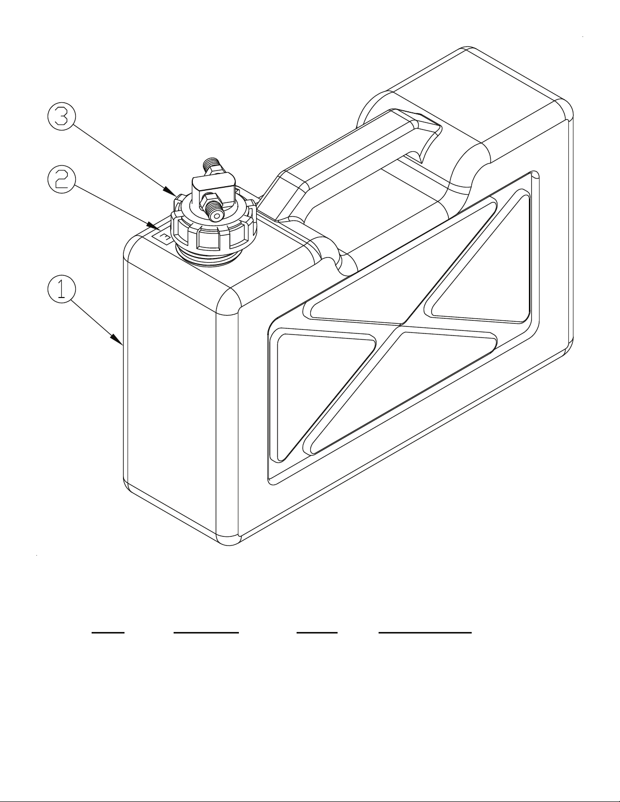
3 2 62395 PLUG, TUBE
4 16 9416904 WASHER, ¼, FLAT
5 1 86890 BASE AY, “U” TUBE
6 10 120392 WASHER, FLAT, ¼, REG
7 14 9419454 NUT, NYLOCK ¼ - 20
8 2 121900 BOLT, ¼-20 x 1, HX
9 4 ASC-19 SCREW, 10-24 x .75, SSTL SHCS
10 2 86881 CLEVIS, REAR
11 1 86883 BRACKET, SLIDE, LEFT HAND
12 2 9419455 NUT, NYLOCK 5/16-18
13 2 65180 KNOB, 5/16 – 18
14 6 65237 WASHER, 1.25˝ DIA x 5/16, FENDER, SSTL
15 6 65211 WASHER, POLYETHYLENE 5/16˝ ID x 1.2
16 2 124824 NUT, 5/16 – 18 HEX
17 4 120394 WASHER, FLAT, 3/8 REG
18 2 65217 BOLT, 5/16-18 x 2.5, SQ. NECK SSTL
19 2 64226-1 CLAMPING KNOB, MACH
20 2 126347 BOLT, CARRIAGE ¼-20 x 2.25
21 1 86884 PLATE, BASE (BH PRC)
22 2 86885 CLEVIS, FRONT (SQ/CIRC)
23 8 86886 SPACER, .375 OD - .21 L, SS
24 2 120375 NUT, HEX, ¼ - 20 ZN PL
25 1 86883-1 BRACKET, SLIDE, RIGHT HAND
10

DYNA-FOG
®
12 V DC PUMPING SYSTEM
FOR BLACKHAWK™ PRO
AND MISTER III™ PRO
MANUFACTURED BY:
CURTIS DYNA-FOG, Ltd.
17335 U.S. Highway 31 North
Westfield, Indiana, U.S.A.
www.dynafog.com
INNOVATORS OF SPRAYING AND FOGGING DEVICES
11

DIAPHRAGM PUMPING SYSTEM
The Dyna-Fog Diaphragm pumping system with by-pass loop was designed to
accurately pump various types of liquid formulations using sprayers and foggers. It
can be used with sprayers with output up to 70 Lt/hr (optional higher rate available).
With the diaphragm pump, the flow rate of the liquid is controlled by a valve as
bypass regulator between the suction (“IN”) line and pressure (“OUT”) lines of the
pump. The more turns that the valve is open, the lower the output that can be
achieved. Additionally, interchangeable restricting orifice is in the line to allow a
fine regulation to the bypass valve and to limit the maximum flow rate of the system.
A pressure gauge is included in the circuit to know the actual flow rate (for this type
of system, the flow rate is proportional to the liquid pressure). As reference, this
manual includes a tabulation of the flow rate respect the liquid pressure when used
oil 467 (viscosity similar to water).
CAUTION
Follow all warnings and cautions on your formulation label.
PRESSURE
GAUGE
VALVE
SOLENOID
DISPLACEMENT
POSITIVE
PUMP TANK
ORIFICE
BYPASS VALVE
RELIEVE
INTERNAL
12

13
12 VDC PUMPING SYSTEM P/N: 86762-2
FOR BLACKHAWK PRO & MISTER III PRO

14
12 V DC PUMPING SYSTEM - MAJOR COMPONENTS DIAGRAM

REMOTE CONTROL BOX
The 12 VDC pumping system with a remote control unit contains an
“ON/OFF” switch.
Switch ON: Applies +12V DC to diaphragm pump motor and opens the
2-way solenoid valve to allow the flow of liquid.
This voltage will be available from the rely only if the
pressure switch is sensing air pressure from the engine
antechamber.
Switch OFF: Removes power to diaphragm pump motor and closes the
2-way solenoid valve to stop the flow of liquid.
REMOTE CONTROL BOX ASSEMBLY
IMPORTANT:
Be sure to turn “OFF” the switch after operation of machine to prevent discharging
battery. Some users prefer to disconnect the remote control from the machine to
avoid the discharge of the battery if the switch is left “ON” when the engine is not
working. Keep the remote control unit where it will not be damaged or lost while the
machine is not working.
15

HOW THE FLOW RATE IS REGULATED
The flow rate is governed by the position of the flow regulation valve (By-pass
regulation), and the restriction(s) used. The machine includes the standard and
permanent orifice #47, located at the brass elbow at the outlet of the solenoid valve.
Additionally, it is supplied as orifice connector #28 which can be used (in addition to
the #47) to work with smaller flow rates.
A
s the flow rate is proportional to the pressure generated when the liquid is passing
thru an orifice, the pressure could be converted to flow as indicated in the next
tabulation of the flow rate, when oil 467 (deodorized Kerosene) is used.
16

ORIFICE #47
Pressure
p.s.i.
Flow Rate
ml/min
26 1110
20 990
15 870
10 675
5 465
Open 360
ORIFICE #47 +ORIFICE #28
Pressure
p.s.i.
Flow Rate
ml/min
29 495
25 450
20 405
15 330
10 240
5 160
Open 60
FLOW RATE
The Flow rate is tabulated for oil 467 (Deodorized Kerosene). The standard and permanent orifi
c
located at the outlet of the pumping system as part of the elbow next to the solenoid
valve. Never remove the orifice 47; it is the element to limit the maximum flow rate.
Do not allow the pump to operate with pressures higher than 30 psi. If a pressure
higher than 30 psi is present, call a Dyna-Fog representative for details about pressure
limit ad
j
ustment of the pump head.
17
orifice

BYPASSING THE AIR PRESSURE SWITCH
The air pressure switch is part of the logic of the circuit, allowing the operation of the
formulation pump only if the air pressure generated at the antechamber of the engine
is present. With this feature the machine is not able to pump (spill) the formulation
when the engine is “OFF” (stopped).
Bypassing the pressure switch enables you (without the engine running),
to determine if the switch is functioning properly.
To Bypass the pressure switch located inside the diaphragm pump enclosure perform
the following:
1. Remove the four screws that hold the enclosure cover to the base plate (see
left side diagram). Carefully remove the cover taking into account that some
wires are still retaining the cover to the wiring of the pump.
2. Remove the orange wire (see right side diagram) from the switch terminal
ANO3" (normally opened), and remove the piece of tubing from terminal
ANC2" (normally closed). Place the orange wire onto terminal ANC2". Doing
this will enable the formulation pump to be operated without the machine’s
engine running.
3. When finished, replace orange wire and tubing back into their original positions (as shown in
the right side diagram).
ENCLOSURE ASSEMBLY, DIAPHRAGM PUMP AIR PRESSURE SWITCH AND CONNECTIONS
18

19

DIAPHRAGM PUMP
The diaphragm pump included
with your machine is the latest
from the pump manufacturer.
IMPORTANT:Spare parts order
for your Diaphragm Pump.
When placing a spare parts
order, please inform us that your
machine is including the new
version of the diaphragm pump,
which includes integrated bypass
in the upper housing, and the
check valve does not include
orifices for relief.
KEY DESCRIPTION KEY DESCRIPTION
1 Bypass Screws 6 Diaphragm Kit (no cam) P/N 64550-3
2 Adjustable Bypass 7 Motor Assembly (Less Base Plate)
3 Pump Screws 8 Motor Rear End Bell Assembly
4 Upper Housing 9 Base Plate/Grommet Assembly
5 Check Valve Assembly P/N 64712-30 10 Bearing Cover
DISASSEMBLE REASSEMBLE
Pump Housing
1. Disconnect power to the pump motor.
2. Remove the four recessed pump-housing screws
(3) located on top of pump housing (4).
3. Remove the pump housing (4) from diaphragm
lower housing assembly.
Check Valve Assembly (5)
4. The check valve housing and O-ring (5) located
in the upper housing (4) or on the diaphragm
cam assembly (5).
5. If in upper housing, remove by placing a small
flat blade screwdriver between the upper
housing and check valve housing and pry out.
Diaphragm/Cam Assembly (6)
6. Remove two deep set phillips head screws (6).
7. Rotate bearing cover (10), so access notch is
aligned with cam bearing screw, loosen set
screw with a 1/8s Allen wrench and slide pump
lower housing assembly from motor shaft.
8. After removing the cam bearing from the outer
piston set, the inner piston screws are now
visible, remove both flat head screws. The outer
piston set can now be removed from the inner
pistons.
Diaphragm/Cam Assembly (6)
1. Place hex stem of inner pistons through the
diaphragm and the openings in the bearing cover
(10) and into piston set.
2. Center pistons in diaphragm and install two flat
head screws.
3. Place cam bearing over outer piston set aligning
locating pins into the holes of the cam bearing
housing.
4. Install round head screws and tighten securely.
Bearing Cover (10)
5. Coat motor shaft with grease prior to installing the
diaphragm/cam bearing assembly (6) to motor.
6. Attach cam bearing assembly to motor shaft by
aligning shaft indentation with set screw and
tighten securely. (Rotate access notches down
toward the base plate.)
7. Install and tighten two phillips head screws to
motor (torque 25 in/lbs.)
Check Valve Assembly (5)
8. Install check valve with new O-ring over the pistons
in diaphragm, discharge side up (side with center
circle up).
Pump Housing (4)
9. Place pump housing (4) over the check valve and
align the four screw holes with bearing cover.
10. Install the four phillips head screws (3) into the
bearing cover and cross tighten securely.
20
This manual suits for next models
3
Table of contents
Other Dyna-Fog Fog Machine manuals