ASSEMBLY
OF
THE
I.F.
CIRCUIT BOARD PC-8
1(
J)
As before,
support
the
board
on
an
open
box
or
between two objects so
that
the
leads
may
project
below the board
as
you
insert
components.
Insert
all
of
the
one-half
watt
resistors,
after
bending
their
leads
as
before.
Be
sure
all
the
resistors
are
seated
firmly
against
the
board.
Tum
the
board
over
and
solder all of
the
leads.
Cut
off
the
excess.
J
2(,j )
Insert
the
one
watt
resistor R22,
the
two
watt
resistors
Rll
and
R13,
and
the four
heater
chokes L6, L7,
L8
and
L9.
Solder
these
in
place
and
trim
off
the
excess leads.
3(
j)
Mount
the
four seven
pin
sockets V3, V4, V5
and
V6.
Note
the
orientation of
the
flat side of
each
socket.
Be
sure each pin penetrates the board
and
does not bend over on top of the board.
Make
sure
that
each socket is
seated
firmly
against
the
board
and
then
solder
all seven pins
and
the
center
ground
pin
of each socket.
4
(/;
Mount
the
nine
pin
socket V7.
Be
sure each pin
penetrates the board
and
does not bend over on top
of
the board.
Seat
it
firmly,
and
solder all nine
pins
and
the
center
ground pin.
5
(J)
Install
capacitors C29
and
C31. Solder all four leads
and
cut
off
the
excess.
6
(J)
Install
all of
the
disc capacitors. As before, the leads
of these capacitors
may
be
bent
slightly to hold
them
in
place,
but
be careful
that
no "bridges"
are
formed
to
adjacent
parts
of the circuit.
Solder
all leads
and
cut
off
the
excess.
7(
I)
Install
PEC
555004, making sure
that
it
is correctly
oriented.
Solder
all three leads
and
cut
off the excess.
8( J)
Insert
the
remaining I.F. transformers
T2,
T3
and
T4
(all
432(01).
Follow
the
location of
the
indi-
cator
at
the top of each transformer
as
shown in
the
pictorial.
Solder
both tabs
and
all
four lugs
on
each
transformer. Avoid excessive solder, which
may
flow
into
the transformer
and
damage it.
The
dis-
criminator transformer
T5
will be
mounted
later.
9(
J)
Note
the orientation of the offset in
the
ground
straps
and
install them
in
each
tube
socket.
Solder
these ground straps.
LO
(
V)
Install
the
pilot light socket. Observe
that
the
con-
necting
tab
from
the
socket
center
contact
goes
into
the
hole
adjoining
eyelet
#20.
Do not install
it
backwards! Solder
both
tabs.
ASSEMBLY
OF
THE
MULTIPLEX BOARD
PC-l
2
1(
J)
Insert
the
one-half
watt
resistors R71
through
R93
in
their
places on
the
board
after
bending
their
leads
as
before. Solder
aU
leads
and
cut
off
the
excess.
2
(J)
Insert
capacitors C71 through C84 in
their
places
on
the
board. Solder all leads
and
cut
off the excess.
NOTE:
It
is
necessary
to
spread
the
leads
of
C76
to
fit
their
hole
spacing.
3 (
J)
Insert
the
two 9-pin sockets V71
and
V72.
Note
the
orientation of
the
flat
side
of
each
socket.
Be
sure
each
pin
penetrates the board
and
does not bend
over
on
top
of
the
board.
Seat
each socket firmly
to
the
board
and
then
solder all
nine
pins
on each
socket. Do not solder the center ground
pin
on
either socket at this time.
4
(rviInstali
the
small wooden wedge
under
the
choke
L71,
and
install L71 so
that
the
thick
part
of
the
wedge is
adjacent
to C81 when
the
choke leads
are
inserted
into
the board.
Solder
both leads
and
cut
off
the
excess.
5(
v)
Mount
the
transformers T71
and
T72
(432003). Be
careful
to
orient
these correctly.
Make
certain that
the indicator
on
top
of the transformer coincides
with
the heavy dash on the board
and
with the pic-
torial.
These
transformers
must
be
seated
firmly
against
the
board,
and
the
two mounting tabs
should
snap
into
place. Solder
both
mounting
tabs
and
all
four lugs
on
each
transforme:.:.
6
(J;
Mount
transformer
T73
(432(04) .
Note
that
this
transformer
can
be
mounted
only one way.
Seat
it
firmly so
that
it
snaps
into
position,
and
make cer-
tain
that
all
5connecting lugs,
as
well
as
the
two
mounting
tabs,
penetrate
the
board.
Do
not solder
lugs
#2
and
#3
as shown
in
the pictorial. Solder
both
mounting
tabs
and
the
other
three lugs.
7(
h
Mount
PEC-l
and
PEC-2
(555001).
Note
that
these identical
units
face in opposite directions.
Solder
all 6leads
and
cut
off
the
excess.
8
(J)
Note
the
orientation of
the
offset
in
the
ground
straps
and
install
them
in
each tube socket. Solder
these ground straps.
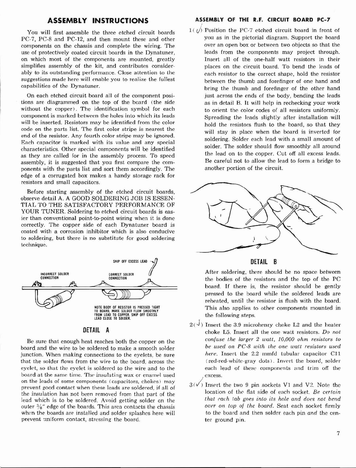
9 (
J)
Observing detail
E,
mount
each of
the
four diodes
D71 through D74.
Those
supplied
may
look like
either
of those in
the
illustration,
and
will have
one
end
painted
red, or
marked
with three stripes.
(Disregard
single green dots
or
stripes.)
DIODE
POLARITY
IS
IMPORTANT.
The
arrowheads
on
the
PC-12 board
point
to
the
marked ends of
the
di-
odes. Diodes should be soldered carefully using the
following technique:
The
leads
should
be
bent
up,
and
looped down
in
the
manner
shown to provide a
"heat
sink."
When
soldering them, grasp
the
loop with a
pair
of pliers from
the top of
the
board to absorb
any
excess
heat,
and
solder from
the
bot-
tom of
the
board.
This
technique
prevents damage to
the
relatively
delicate diodes from excessive heat.
DETAIL
E
This
completes
the
assembly of
the
etched
circuit
boards.
Your
FM-3
is now
almost
half completed.
9