manuals.online logo
Brands
  1. Home
  2. •
  3. Brands
  4. •
  5. Dynabrade
  6. •
  7. Sander
  8. •
  9. Dynabrade 4657971919 User manual

Dynabrade 4657971919 User manual

Other Dynabrade Sander manuals
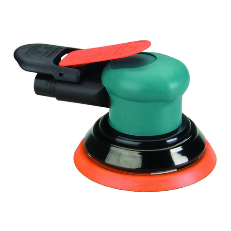
Dynabrade 10170 User manual

Dynabrade

Dynabrade 10170 User manual

Dynabrade 59306 Guide

Dynabrade

Dynabrade 59306 Guide

Dynabrade Dynorbital Supreme 57655 User manual

Dynabrade

Dynabrade Dynorbital Supreme 57655 User manual

Dynabrade 300CE Guide

Dynabrade

Dynabrade 300CE Guide

Dynabrade 50320 User manual

Dynabrade

Dynabrade 50320 User manual

Dynabrade 51611 Guide

Dynabrade

Dynabrade 51611 Guide

Dynabrade 57550 User manual

Dynabrade

Dynabrade 57550 User manual

Dynabrade 5700 User manual

Dynabrade

Dynabrade 5700 User manual

Dynabrade 51820 User manual

Dynabrade

Dynabrade 51820 User manual

Dynabrade 51390 User manual

Dynabrade

Dynabrade 51390 User manual

Dynabrade 47820 Installation guide

Dynabrade

Dynabrade 47820 Installation guide

Dynabrade 51520 Quick start guide

Dynabrade

Dynabrade 51520 Quick start guide

Dynabrade 18066 Guide

Dynabrade

Dynabrade 18066 Guide

Dynabrade Dynabug 57920 User guide

Dynabrade

Dynabrade Dynabug 57920 User guide

Dynabrade Nitro ROB2 Series Guide

Dynabrade

Dynabrade Nitro ROB2 Series Guide

Dynabrade 10727 User manual

Dynabrade

Dynabrade 10727 User manual

Dynabrade X32V User manual

Dynabrade

Dynabrade X32V User manual

Dynabrade 57220 User guide

Dynabrade

Dynabrade 57220 User guide

Dynabrade Dynabug II 10280 User manual

Dynabrade

Dynabrade Dynabug II 10280 User manual

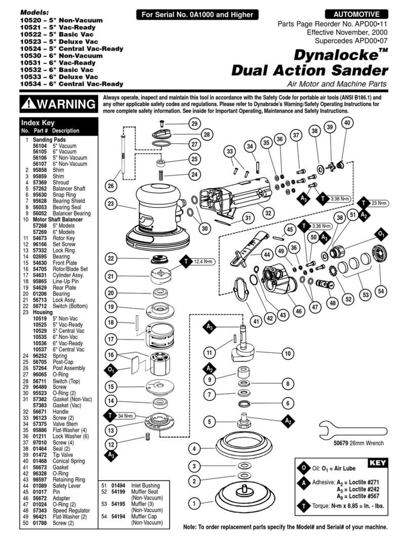
Dynabrade Dynalocke 10520 User manual

Dynabrade

Dynabrade Dynalocke 10520 User manual
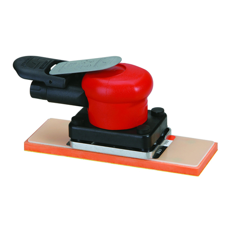
Dynabrade Dynafile II 40500 Quick guide

Dynabrade

Dynabrade Dynafile II 40500 Quick guide

Dynabrade 48500 Guide

Dynabrade

Dynabrade 48500 Guide

Dynabrade 52900 Manual

Dynabrade

Dynabrade 52900 Manual

Dynabrade 52596 User manual

Dynabrade

Dynabrade 52596 User manual

Popular Sander manuals by other brands

FXA FXAJD2523 instruction manual

FXA

FXA FXAJD2523 instruction manual

Grizzly T33256 owner's manual

Grizzly

Grizzly T33256 owner's manual

Silverline 631320 User instructions

Silverline

Silverline 631320 User instructions

Black & Decker 7041 instruction manual

Black & Decker

Black & Decker 7041 instruction manual

DeWalt D26441 instruction manual

DeWalt

DeWalt D26441 instruction manual

OMCA SMR 930 Handbook

OMCA

OMCA SMR 930 Handbook

Schleifhexe BS 200 Original instructions

Schleifhexe

Schleifhexe BS 200 Original instructions

Ryobi RPS80 Original instructions

Ryobi

Ryobi RPS80 Original instructions

Oliver 6305 owner's manual

Oliver

Oliver 6305 owner's manual

Jet 22-44 Pro-3 Operating instructions and parts manual

Jet

Jet 22-44 Pro-3 Operating instructions and parts manual

Workzone 47561 user guide

Workzone

Workzone 47561 user guide

Makita M9204 technical information

Makita

Makita M9204 technical information

Makita M9204 instruction manual

Makita

Makita M9204 instruction manual

Clarke Woodworker CBS1-5B Operation & maintenance instructions

Clarke

Clarke Woodworker CBS1-5B Operation & maintenance instructions

Chicago Pneumatic CP9778 Operator's manual

Chicago Pneumatic

Chicago Pneumatic CP9778 Operator's manual

Ferm FEOS-135 user manual

Ferm

Ferm FEOS-135 user manual

Unior 1510 Operating	 instruction

Unior

Unior 1510 Operating instruction

stayer ls1200 operating instructions

stayer

stayer ls1200 operating instructions

manuals.online logo
manuals.online logoBrands
  • About & Mission
  • Contact us
  • Privacy Policy
  • Terms and Conditions

Copyright 2025 Manuals.Online. All Rights Reserved.

Disassembly Instructions – Dynabug Sander
Important: Use these instructions along with the tool parts page or manual.
Notice: To avoid damage, use the special repair tools contained in the 57098 Motor Repair Kit.
Shut off the air supply and deplete air from the hose. Disconnect the tool from the air supply.
Motor Disassembly:
1. Position the 57092 Repair Collar around the housing.
Fasten the sander in a vise with the sanding pad facing up. Notice: Do not over tighten
the sander in the vise. Over tightening will make it difficult to remove the 57059 Lock
Ring. (SEE STEP #3)
Use a 3 mm hex key to remove the pad screws (4).
57092 Repair Collar
3 mm hex key
Use a 3/16" hex key to remove the 96168 Screw.
Use a Phillips screwdriver to remove the 96114 Screws (6).
Remove the 57825 Pad Top.
3/16" hex key
2. Use a slot-blade screwdriver to loosen the 96116 Clamp. Remove the clamp, 57822 Boot
and 57823 Pad Mount.
3. Use the 56058 Lock Ring Wrench to loosen the 57059 Lock Ring. Turn counterclockwise.
4. Pry-up, under the motor shaft balancer to remove the air motor from the housing.
Remove the 57054 Rear Ring from the inside of the housing.
5. Use retaining ring pliers to remove the 95626 Retaining Ring.
6. Fasten the 96346 Bearing Separator (2") around the 57058 Cylinder. Place the bearing
separator and motor in the 96232 Arbor Press (#2) with the counterweight pointing down.
Use the arbor press and a 5/16" or 8 mm diameter flat-end press tool to push the shaft
out of the 01206 Bearing.
7. Remove the rotor, vanes, key, and front bearing plate.
Use the bearing separator and the arbor press ram to remove the 57088 Bearing.
96346 Bearing Separator
8. By hand, or with the arbor press, use the 96214 Bearing Removal Tool to remove the 01206
Bearing from the 57056 Rear Bearing Plate.
9. Balancer Bearing and Shaft Disassembly:
a) Fasten the counterweight in a vise with aluminum or bronze jaws so that the hex of the
57069 Balancer Shaft is pointing up. Use a thin slot-blade screwdriver to pick-out the end
of the 95630 Snap Ring and remove the snap ring from the motor shaft balancer.
96214 Bearing Removal Tool
b) To break the adhesive bond, use two flat-blade screwdrivers (large) to pry-up on the
balancer shaft and bearing. Notice: If necessary, use a HEAT GUN to apply heat to
the counterweight.
Use the 56056 Bearing Puller to remove the balancer shaft and the 56052 Bearing.
c) Fasten the bearing separator between the 56052 Bearing and the hex end of the 57069
Balancer Shaft.
Place the bearing separator and the balancer shaft in the arbor press with the hex
end pointing down. Use the arbor press ram to break the adhesive bond.
Use a 5/16" or 8 mm diameter flat-end drive punch as a press tool to push the balancer
shaft out of the 56052 Bearing.
Remove the 59084 V-Seal.
Motor Disassembly Completed.
RAM