DYNACO PAT-5 User manual

Page 1 of 21
Updatemydynaco
Dynaco PAT-5 Preamp
Power Supply (PAT5PM15)
+/-15 Volts only
ASSEMBLY MANUAL
© 2021 AkitikA LLC
All rights reserved
Revision 1p08 March 27, 2021

Page 2 of 21
Table of Contents
Table of Contents ................................................................................................................ 2
Table of Figures .................................................................................................................. 3
Section 1: About This Manual ............................................................................................ 4
Who Should Attempt this Project? ................................................................................. 4
Tools you’ll need ............................................................................................................ 4
Helpful Tools .................................................................................................................. 4
Project Overview ............................................................................................................ 5
Important Safety Notes ................................................................................................... 5
About Components ......................................................................................................... 5
Recommended Solder ..................................................................................................... 5
Warranty ......................................................................................................................... 5
Section 2: Kit Building Hints .............................................................................................. 6
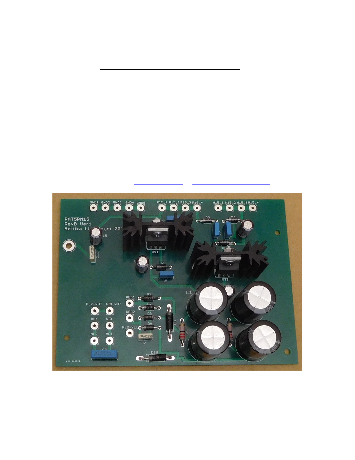
Section 3: Building the Power Supply ................................................................................ 7
Component Order............................................................................................................ 8
Install the diodes ............................................................................................................. 8
Install the Resistors ......................................................................................................... 8
Install the non-polar Capacitors ...................................................................................... 9
Install the Polarized Electrolytic Capacitors ................................................................... 9
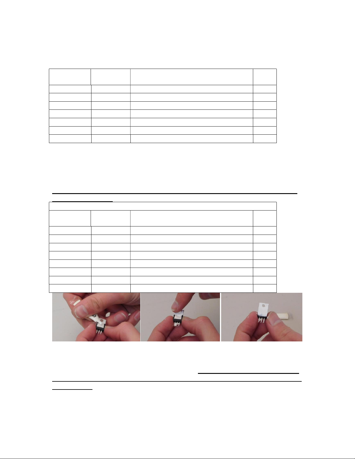
Install the TO-220 Regulators and Heatsinks ................................................................. 9
Check your work ........................................................................................................... 11
Removing the Old Power Supply ..................................................................................... 11
Connect the Transformer .................................................................................................. 13
Connecting the low voltage transformer wires ......................................................... 13
Connecting the AC line-side transformer wires ........................................................ 14
Connecting AC Power to the PCB ............................................................................ 15
What if PAT5PM Is Installed? .................................................................................. 15
Take a break .............................................................................................................. 15
Testing the New Power Supply................................................................................. 16
Installing the New Power Supply ................................................................................. 17
Complete Zig-Zag Wall and back panel re-Installation ............................................ 18
Re-connect Power Supply to Preamp and Phono Sections ....................................... 18
Testing the Power Supply Line-Stage Combination ................................................. 20
Final Re-Assembly.................................................................................................... 20
Schematic ...................................................................................................................... 21

Page 3 of 21
Table of Figures
Figure 1-Assembled PAT-5 Power Supply......................................................................... 6
Figure 2-Empty the power supply components into a soup bowl ....................................... 7
Figure 3-Silk screen shows power supply component locations ........................................ 7
Figure 4-Applying thermal compound ................................................................................ 9
Figure 5-Regulator and Heat Sink mounting screws and soldering mounting posts ........ 10
Figure 6-Assembled Power Supply .................................................................................. 10
Figure 7-Remove hardware that holds power supply bracket to chassis floor ................. 11
Figure 8-Remove these 2 screws and 2 screws on the opposite side ................................ 12
Figure 9-Remove the screws and nuts that hold the zig-zag shield to back and front of
chassis ............................................................................................................................... 12
Figure 10-Original Transformer wiring ............................................................................ 13
Figure 11-Mount new PCB to shield and mounting brackets ........................................... 17
Figure 12-wiring power from back to front with jumpers ................................................ 19
Figure 13-Separate runs for power to phono stages and line stages ................................. 19
Figure 14-Schematic of Power Supply ............................................................................. 21

Page 4 of 21
Section 1: About This Manual
This manual gives the information needed to build and install the upgraded power supply
for Dynaco’s PAT-5 Preamp. This upgrade changes out the power supply PCB but keeps
the power supply transformer, with the following advantages over the original power
supply:
Lower noise
Lower output impedance
More efficiency, runs cooler, promotes longer life of the electronics
Use this power supply, the PAT5PM15, if you are using Updatemydynaco line stages and
phono stages. This power supply does generate +/-15 volts, but it doesn’t generate the 42
volts required by the original PAT-5 phono preamp. If you’re keeping the original PAT-5
phono preamps, you’ll want to use the PAT5PWR supply that we make.
Important Note: this kit and the transformer are only compatible with 120 VAC power.
Who Should Attempt this Project?
You can build this kit if you can:
1. Solder (using normal rosin core solder and a soldering iron).
2. Use simple hand tools like screwdrivers, wire cutters, and pliers.
3. Read and follow directions.
It helps if you:
1. know a bit about electronics, or
2. have a friend who knows a bit about electronics
3. can get to YouTube to watch a few helpful videos about the assembly process
(none are posted as of this version of the manual).
Tools you’ll need
You’ll need the following tools:
1. Phillips screwdriver (#1 and #2), regular screw-drivers.
2. Pliers or nut drivers suitable for #4 and #6 hardware
3. needle nose pliers (helpful, but not strictly necessary)
4. pencil type soldering iron of 25 to 50 Watts (no huge honking soldering guns or
blowtorches)
5. wire cutters and strippers
6. multi-meter to measure power supply voltages and confirm resistor values
(strongly recommended)!
Helpful Tools
These tools aren’t strictly necessary but make building the kit easier.
1. magnifying glass, if you’re over 42!
2. lead bending jig to form axial component leads to the correct span for insertion in
the PCB.

Page 5 of 21
Project Overview
The project consists of the following steps:
1. Building the circuit board.
2. Removing the old power supply
3. Installing and testing the new power supply
4. Completing re-assembly of the preamp.
Important Safety Notes
By purchasing, using, or assembling this kit, you have agreed to hold Akitika LLC
harmless for any injuries you may receive in its assembly and/or use. To prevent injuries:
Wear safety glasses when soldering or clipping wires to prevent eye injuries.
Always unplug the power before working on the amplifier.
Large capacitors hold lots of energy for a long time. Before you put your hands
into the amplifier:
o Pull the AC plug!
o Wait 2 full minutes for the capacitors to discharge!
Remove jewelry and rings from your hands and wrists, or anything that might
dangle into the amplifier.
If working one the equipment with the power on, keep one hand in your pocket,
especially if you’re near the power supply or power supply wires. This can
prevent serious shocks.
Build with a buddy nearby. If you’ve ignored all the previous advice, they can
dial 911 or get you to the hospital.
Read and understand the safety manuals of all the tools you use.
About Components
We reserve the right to make design/or component changes at any time without prior
notification.
Recommended Solder
The kit must be assembled with 63/37 Rosin Core solder1. The recommended diameter is
0.032 inches.
Warranty
With the exception of fuses, Akitika LLC will replace for free any parts of a correctly
assembled product that fails within one year of the date of purchase when the equipment
has been used in home stereo applications. It is the responsibility of the kit builder to
install the replacement part(s). This warranty applies to the original purchaser only. It
does not apply to units that have been physically or electrically abused, modified without
prior factory authorization, or assembled with other than 63/37 Rosin Core solder.
Akitika LLC’s liability shall in no event exceed the cost paid to Akitika LLC for the kit.
1 60/40 solder is also available, but according to Wikipedia, 63/37 solder is preferred as it is less likely to
have a “cold” solder joint.

Page 6 of 21
Section 2: Kit Building Hints
Yes, I know you want to ignore this section, and jump right into building the kit.
However, please take a minute and read the advice of this section. I’ve condensed it into
bullets so that even you guys who are in a hurry can benefit.
Stop any time you’re feeling confused, tired, or anxious. Taking breaks at those
strategic times will keep the build enjoyable and greatly enhance your chances of
first-time success.
A soup bowl is your friend. Before you build a board, carefully empty the parts
into a broad, flat, light colored soup bowl. That makes it easy to find the parts and
keeps them from getting lost.
A digital ohm-meter is an easy way to make sure that you’ve picked the right
resistor. It’s a great cross-check on the resistor color code. Measure twice and
solder once!
A lead-bending jig can make for quicker, neater assembly. It’s certainly not
necessary.
Is something in this manual confusing? Does something look wrong? Send your
questions by email to [email protected] or dan@updatemydynaco.com. You’ll
help yourself and everyone who builds the kit.
Figure 1-Assembled PAT-5 Power Supply

Page 7 of 21
Section 3: Building the Power Supply
This section details the process of building the power supply circuit board. Begin by
carefully emptying the contents of the parts envelope into a broad soup bowl, as shown
below. In general, you’ll start with the components that lay closest to the board, working
your way towards the taller components.
Figure 2-Empty the power supply components into a soup bowl
Figure 3-Silk screen shows power supply component locations

Page 8 of 21
Component Order
You’ll notice that the component designations in the directions don’t go exactly in order.
We have grouped them so that all components with the same value appear together. This
makes assembly easier. You’ll find in the parts kit that similar parts, e.g. 8 1N4004
diodes, are typically (though not always) taped together.
Install the diodes
In general, you install axial leaded components (like the diodes) by placing the body on
the silk screen side of the board, and the leads through the indicated holes. Bend the leads
over on the back of the board to keep the components from falling out until your solder
them in place. Try to bend the leads in a direction that won’t lead to solder bridges
between traces that should remain disconnected.
We recommend the following procedure:
1. Insert all components of the same value or type
2. Bend the leads as described above.
3. Solder the leads on the back of the board.
4. Clip the leads.
Track your progress by placing a checkmark in the done column as you install each
component.
Diodes are polarized, having an anode and a cathode. When you insert the diode, match
the banded end of the diode to the banded end of its representation on the silk screen.
Diodes – watch the polarity! – bend leads to 0.4” width
Designation
Type
Rating,
Marking
, Description
Done? (
)
D1
1N4004
400 PIV 1 Amp, 1N
4004,
rectifier diode
D2
1N4004
400 PIV 1 Amp, 1N4004, rectifier diode
D3
1N4004
400 PIV 1 Amp, 1N4004, rectifier diode
D4
1N4004
400 PIV 1 Amp, 1N4004, rectifier diode
D5
1N4004
400 PIV 1
Amp, 1N4004, rectifier diode
D6
1N4004
400 PIV 1 Amp, 1N4004, rectifier diode
D7
1N4004
400 PIV 1 Amp, 1N4004, rectifier diode
D8
1N4004
400 PIV 1 Amp, 1N4004, rectifier diode
D
9
1N5364
33 Volt, 5 Watt Zener Diode
D10
1N5364
33 volt, 5 Watt
Zener Diode
Install the Resistors
Bend resistor leads to 0.5” width
Designation Value Color Code Done
R1
22
Red, red, black, gold (1 Watt, 5%)
R2
22
Red, red, black, gold (1 Watt, 5%)

Page 9 of 21
Install the non-polar Capacitors
These capacitors are not polarized, so it doesn’t matter which way they are installed on
the printed circuits.
Designation Value Description Done
C5
0.
1
µF
100
V
olt
,
film
C6
0.
1
µF
100 Volt, film
C9
0.1 µF
100 Volt, film
C10
0.1 µF
100 Volt,
film
C7
0.01 µF
400 Volt
, film
C1
1
0.
0
1 µF
4
00 Volt, film
C8
0.033µF
300 Volt Safety Cap, film
Install the Polarized Electrolytic Capacitors
These capacitors have a polarity. If you put them in backwards:
The power supply won’t work
The capacitors may explode sending their insides racing to the outside
Please re-read the above sentence, and double check the capacitor polarity before you
solder them in place!
Please double check the polarity of each
capacitor upon installation
Designation Value Description Done
C12
47 µF
35 Volts, electrolytic
C13
47 µF
35 Volts, electrolytic
C14
47 µF
35 Volts, electrolytic
C15
47 µF
35 Volts, electrolytic
C1
2200 µF
35 Volts, electrolytic
C
2
2200 µF
35 Volts, electrolytic
C
3
2200 µF
35 Volts, electrolytic
C
4
2200 µF
35 Volts, electrolytic
Figure 4-Applying thermal compound
Install the TO-220 Regulators and Heatsinks
There are two regulators, both in TO-220 packages. Be warned…they are different, and
they are not interchangeable. Make sure you double check your work before you solder
them in place.
1. Start with U$1, the µA7815. Spread a thin film of heatsink compound on the back
of the regulator, see Figure 4.

Page 10 of 21
2. Fasten the regulator to the heat-sink using a 4-40x5/16” Phillips head screw and
4-40 keps nut (a nut with a built-in lock washer) as shown in Figure 5.
3. Insert the regulator/heat-sink assembly into the PCB.
4. Turn the board over and solder the cylindrical projections of the heatsinks to the
circular pads on the bottom of the PCB. This will take a lot of heat and solder.
5. Solder the 3 leads of the regulator to their associated pads.
6. Repeat the above process for U$2, the LM7915.
Figure 5 shows the details of the mounting screws and soldering the heat-sink posts on
the bottom of the board.
Please double
check the regulator type
upon installation
Designation Value Description Done
U$1
µA
7815
Positive 15 Volt Linear Regulator
U$2
LM7915
Negative 15 Volt Linear Regulator
Figure 5-Regulator and Heat Sink mounting screws and soldering mounting posts
Figure 6-Assembled Power Supply

Page 11 of 21
Check your work
Look over the board to verify that:
1. All components are soldered.
2. No solder bridges are apparent.
3. Polarity of the electrolytic capacitors is correct.
4. The right regulator is in the right location.
5. The heatsink hardware is tight.
6. Diode polarity is correct.
If everything looks good, you’re ready to install the power supply into your PAT-5.
Removing the Old Power Supply
The mechanical design of the PAT-5 Preamp makes removing the old power supply a lot
of work. Your soup bowl will come in handy again as a safe place to collect all the bits
and pieces you’ll need to remove to change the power supply.
Figure 7-Remove hardware that holds power supply bracket to chassis floor
All of the following steps have the goal of removing the power supply and the power
supply wall, allowing replacement of the old power supply with the new.
Note: You will re-use the 4-40 screws in your kit, so be sure to save them. However, we
have supplied 4-40 keps nuts. A keps nut has a captive lock-washer. These keps nuts
will replace the separate nuts and lock-washers originally used for PAT-5 assembly.
Prepare to remove the old power supply
Done? (
)
Pull the Preamp’s AC plug and wait 1 minute
before going on.
Remove the two screws (one in each bracket) that hold the silver colored
power supply mounting brackets to the bottom of the chassis. Easiest access
is from the screws at the bottom of the chassis
(
Figure
7
)
.
Remove the four side screws that hold the back panel to the bottom of the
chassis.
(2 along each side
, near the back, see
Figure
8
).

Page 12 of 21
Remove the two 4-40 screws and nuts from the back panel that hold the zig-
zag shield and the power supply mounting bracket. Try to not let the nuts or
lock washers
get away from you
(
Figure
9
)
.
Use a 1/16” Allen wrench to remove all the front panel knobs. I like to turn
all the knobs fully counterclockwise before I start. It makes all the set
screws available and give me a consistent place to re-set all the knobs when
it’s time to re
-
assemble the preamp.
Remove the 3 nuts on the control shafts that hold the front panel in place.
These are typically located on the input selector, balance, and speaker
control
s
. R
emove the front panel
Remove the two 4-40 screws and nuts that fasten the front of the zig-zag
shield to the front panel
(
Figure
9
)
.
Lift the back panel slightly to clear the lip on the bottom of the chassis.
There is enough slack in the wires to move the back panel back a bit. That
op
ens up enough room to lift out
the zig
-
zag shield and power supply.
Lift the power supply and zig
-
zag shield assembly out of the preamp.
Figure 8-Remove these 2 screws and 2 screws on the opposite side
Figure 9-Remove the screws and nuts that hold the zig-zag shield to back and front of chassis

Page 13 of 21
Remove the old power supply
Done? (
)
Remove the four screws (two in each bracket) that hold the silver colored
power supply mounting brackets to the
old
power supply PCB.
Disconnect Transformer wires from the old PCB
Done? (
)
Desolder the two red wires
from the old PC Board.
Desolder the Red
-
yellow wire from the old PC board.
Desolder the violet and violet
-
white wires from the fuse holder.
Disconnect the transformer wires from the chassis
Desolder the black and black-white wires from their connection point on the
convenience outlet. However, make note of this terminal as a wire will be
reconnected here in a later step.
Figure 10-Original Transformer wiring
Connect the Transformer
Make absolutely sure that your PAT-5 is unplugged!
You will re-use the original Dynaco power transformer. In its new connection
arrangement, the total power drawn by the PAT5 drops from 10 Watts to 7 Watts. That’s
because the new arrangement is more efficient than the stock arrangement.
When the new power supply is installed, except for the green shield wire, all of the
transformer wires will terminate on the new power supply PCB.
Connecting the low voltage transformer wires
1. Identify the following 3 transformer wires
a. First red wire
b. Second red wire

Page 14 of 21
c. Red/yellow wire
2. Form the three wires into a twisted trio.
3. Insert the wires from the component side of the board and solder them on the
solder side.
a. Either red wire may connect to RED1
b. The remaining red wire connects to RED2
c. The Red/yellow wire connects to RED-YEL
Connecting the AC line-side transformer wires
Assuming your PAT5 was previously wired for 120V, you will find that:
Black-White and Black transformer wires were twisted together
Violet-White and Violet transformer wires were twisted together
As you perform the steps below, you will untwist these pairs, and form new twisted pairs
out of these four wires.
Make absolutely sure that your PAT-5 is unplugged!
1. Identify the following 2 transformer wires:
a. Violet
b. Black-white
c. Verify that you have the correct pair by measuring the DC resistance
between these two wires. The DC resistance is around 120 Ohms2.
2. Twist these insulated wires together to form a new twisted pair. (Violet and
Black-White) Of course, their ends remain independent.
3. Insert the wires into the component side of the board and solder them on the
solder side. Leave the wires as long as possible, but if their lengths differ greatly,
you will probably want to equalize them to the length of the shorter wire in the
pair. Just make sure that it will reach when everything is put back in place.
a. Connect the Violet wire to the VIO eyelet on the PCB.
b. Connect the Black/white wire to the BLK-WHT eyelet on the PCB.
4. Identify the following 2 transformer wires
a. Violet-White
b. Black
c. Verify that you have the correct pair by measuring the DC resistance
between these two wires. The DC resistance is around 120 Ohms.
5. Twist these insulated wires together to form a new twisted pair (Violet-White and
Black). Of course, their ends remain independent.
6. Insert the wires into the component side of the board and solder them on the
solder side. Leave the wires as long as possible, but if their lengths differ greatly,
you will probably want to equalize them to the length of the shorter wire in the
pair. Just make sure that it will reach when everything is put back in place.
a. Connect the Violet/white wire to the VIO-WHT eyelet on the PCB.
b. Connect the Black wire to the BLK eyelet on the PCB.
2 The resistance you find as you measure the DC resistance of these windings may vary by plus or minus
10% from the quoted value.

Page 15 of 21
Connecting AC Power to the PCB
Make absolutely sure that your PAT-5 is unplugged!
The only thing that remains to do is to connect the fused 120 volt power to the
transformer. Locate the supplied piece of twisted white/black 22 AWG stranded wire.
1. Cut it to a 13” length.
2. On one end, untwist about three inches of the wires.
3. Cut off 3” of the white wire on that end.
4. Strip ¼” of insulation from the four ends of the wires. Twist and tin the four wire
ends.
5. Solder the short white wire to the fuse terminal closest to the side of the
enclosure. Recall that you removed the transformer violet-white and violet wires
from this fuse terminal in a previous step.
6. Solder the black wire from that end of the twisted pair to the convenience outlet
terminal (outlet C, terminal 1 in Figure 10). Recall that you earlier had
disconnected the black-white and black twisted pair from this terminal.
7. Route the black/white twisted pair along the same path as was previously taken by
the transformer wires, along the side of the chassis.
8. Insert the unconnected white wire into the AC1 eyelet from the component side of
the board and solder it on the solder side.
9. Insert the unconnected black wire into the AC2 eyelet from the component side of
the board and solder it on the solder side.
What if PAT5PM Is Installed?
The transformer wiring changes in this manual puts the power transformer windings in
series, rather than parallel. These changes are independent of the power switch re-wiring
undertaken in the PAT5PM (Power on mute) manual. Therefore, the wiring for this
power supply installation does not change if the PAT5PM is present or absent. In both
cases:
1. power supply white wire goes to the side of the fuse closest to the side wall.
2. Power supply black wire goes to outlet C terminal 1.
The difference between PAT5PM wiring (switching the power to the power supply) and
standard wiring (leaving the power supply always powered) remains independent of the
changes described in this manual.
Take a break
You have just reached a rather important milestone. Get up, walk around, say hi to your
significant other or the family pet. You’re about to apply power to the PAT5 to test the
power supply, and it’s always a good idea to have clear head before doing anything that
involves the AC mains.

Page 16 of 21
Testing the New Power Supply
Safety Warnings:
Clean-up and make sure that no tools are inside the preamp. You’re about to
power it on to test the output voltages. Remember to be safe, as potentially lethal
voltages will be present in the next step
.
Re-installing the power supply is a lot of work. It’s probably a good idea to test the
supply before you re-install it. Follow these steps:
1. Make sure that the power cord is unplugged.
2. Fold a piece of 8.5”x11” paper in a U-shape around the bottom and sides of the
power supply. The idea is to form a temporary insulator that will keep the PCB
from making electrical contact where it should not.
3. Set the combination of the power supply and paper temporary insulator into the
chassis, close to its normal position.
4. Look at the arrangement to make sure that nothing from the power supply can
contact the chassis. If necessary, add a second piece of paper.
Be Careful. The next step makes 120Volt AC accessible inside the unit.
5. Plug in the power cord and turn on the power switch. Stand back and look for a
minute. There should be no excitement. Pull the plug immediately if you see
evidence of smoke or fire. If all is calm after 1 minute, go on to the next step.
6. Measure the DC voltage from any of the P15 terminals to the GND terminals. It
should be 15+/-1 Volts.
7. Measure the DC voltage from any of the N15 terminals to the GND terminals. It
should be -15+/-1 Volts.
Pull the plug from the AC wall socket (mains). If the voltages were correct, go on to the
next section. If the voltages were not correct, then examine your board for missed solder
joints, backwards diodes, missing components, backwards capacitors, swapped
regulators, and the like. There is no point in going on until the power supply is
functioning correctly. If you get stuck, send email to [email protected].

Page 17 of 21
Installing the New Power Supply
Figure 11-Mount new PCB to shield and mounting brackets
Installing the new power supply
Done? (
)
Pull
the Preamp’s AC plug and wait 1 minute before going on.
Mount the new power supply to the zig-zag shield using four 4-40 screws
and the supplied 4-40 KEPS nuts into the power supply mounting brackets.
KEPS nuts, with their captive lockwasher makes reassembly easier. Figure
11
shows the correct order of the brackets, PCB, and screws.
Use two of the silver colored 4-40 screws and supplied 4-40 KEPS nuts to
fasten the power supply mounting brackets to the bottom of the chassis.

Page 18 of 21
Complete Zig-Zag Wall and back panel re-Installation
Make sure that the PAT-5 Preamp is unplugged before going on!
Use two silver colored 4-40 screws and the supplied 4-40 KEPS nuts to
fasten the zig-zag shield to the front panel. It’s hard to get your fingers in
place to hold the nuts. I like to hold the nut in place using double sided tape
wrapped around the blade of a flat screwdriver. I then use a second
screwdriver
to turn the screw.
Re-use the four (2 on each side) ¼” hex head self-tapping screws to fasten
the back panel to the chassis bottom. Make sure that the back panel sits just
inside the lip on the bottom of the chassis.
Use two silver colored 4-40 screws and the supplied 4-40 KEPS nuts to
fasten the zig
-
zag shield to the back panel.
Re-connect Power Supply to Preamp and Phono Sections
Make sure that the power plug is pulled before proceeding.
The big picture is this. We want to reconnect +15V, GND, and -15V from the power
supply to the phono preamps and line stages. Follow the following color code if you use
the supplied wire:
Black is Ground
Red is +15V
Blue is -15V
There are a number of ways you could do this. The follow pictures sketch the variations.
We assume in both sketches that you have followed the standard directions for the
preamp and phono sections, where the left and right channels of each set have their
powers and ground connected by jumpers between the boards.

Page 19 of 21
Figure 12-wiring power from back to front with jumpers
Figure 13-Separate runs for power to phono stages and line stages

Page 20 of 21
Testing the Power Supply Line-Stage Combination
Be safe as you plug in the AC cord. Remember that lethal voltages will be
present inside the preamp.
Verify that the power supply output voltages are still in tolerance after
connecting the power supply to the rest of the preamp.
Measure DC voltage from any of the P15 terminals to any of the GND
terminals
. It should be 15 Volts, plus or minus 1 volt.
Measure DC voltage from any of the N15 terminals to any of the GND
terminals
. It should be
-
15 Volts, plus or minus 1 volt.
Final Re-Assembly
Once you have verified correct voltages, it’s time to return your PAT-5 Preamp to
service.
Putting on the Cover
Done? (
)
Place the cover on the preamp. Note that there is only one correct
orientation. You’ll see the 4 holes on the sides line up when the orientation
is correct.
Install the 4 black screws (2 on each
side
) that hold the cover in place
Install the black screw that holds the center-back of the cover to the back
panel.
Other manuals for PAT-5
1
This manual suits for next models
1
Table of contents
Popular Power Supply manuals by other brands

Roger
Roger PS15v24-BRD user manual

Pulsar
Pulsar PSU-U-24V/AC-4A/4/FTA/PTC-TR-MC manual

Heritage MedCall
Heritage MedCall HM-535 Installation and service instructions

National Instruments
National Instruments NI PXI-1006 user guide

Ericsson GE
Ericsson GE MASTR II 19A149979P1 Maintenance manual

VitrineMedia
VitrineMedia Power Box manual

Allied Telesis
Allied Telesis IE048-480 installation guide

Seasonic
Seasonic ARCH Q5 Series installation guide

Pulsar
Pulsar AWZ 12V/1A/5x0,5A manual

SEW
SEW MDR60A operating instructions

Optimal Power
Optimal Power OPR Power OPR150-24S manual

Rockwell Automation
Rockwell Automation Allen-Bradley 1606-XLE240EDRZ SER B installation instructions