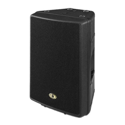
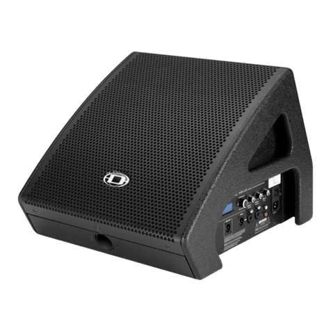
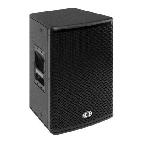
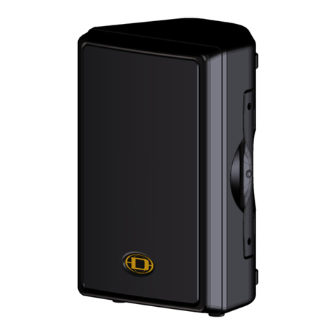
Dynacord CXM15 User manual

special reprint 12/09_01/10 production partner
1
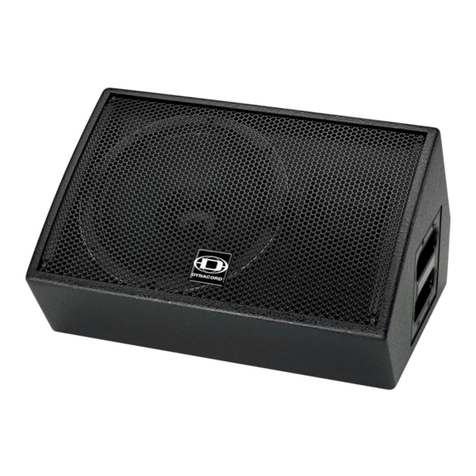
The CXM 15 from Dynacord, a manufacturer
based in Straubing (Germany), is a 15"/1.4" box
with a wedge design. The cabinet has been
kept especially flat and compact so as to be as
unobtrusive and easy to position as possible
on stage. Despite the advent of in-ear monito-
ring, floor monitors are no relic of the past.
On grounds of cost alone and the relatively
time-consuming handling, in-ear monitoring
is often not possible, and a great many per-
formers and technicians in any case prefer
classical monitoring on stage – and for a wide
variety of reasons. The demands placed on
the loudspeakers used on stage are very high:
"unobtrusiveness" is of particular importance
if the set is to remain uncluttered and the
lines of sight of audience members (and
cameras) unobstructed.
From an acoustic standpoint, a consistent
directionality and a frequency response
free from narrow-band ridges are what is
required, the aim in each case being to
reduce susceptibility to feedback, as – along
with the polar pattern of the microphones
– the performance of the monitors plays a
leading role here. Depending upon the
application, further factors, such as the ade-
Dynacord CXM15
Coaxial floor monitor with optional FIR processing
ARTICLE FROM PRODUCTION PARTNER 12/09_01/10
www.production-partner.de www.promedianews.de
PRODUCTION
PARTNER

2
production partner 12/09_01/10 special reprint
Dynacord CXM15
TEST
quacy of sound pressure levels, are of grea-
ter or lesser importance. Since stage moni-
tors are usually operated at close range –
between one and three metres from the
performer – the sound should as far as pos-
sible radiate from a single source.
CXM 15
For the aforementioned reasons, the CXM
15 is conceived as a coaxial two-way sys-
tem. A further advantage of this constru-
ction is the reduced area of the front panel,
which makes the box more compact. The
two sides of the enclosure are angled at 33°
and 45°, the depth of the cabinet being 329
mm. These compact dimensions for a 15"
woofer indicate already that the box is not
necessarily optimized for deep bass repro-
duction, but this is in any case not what is
generally wanted in a stage monitor. The
size of the enclosure is clearly here the pri-
mary consideration. Genuine deep bass
reproduction on stage is only required, if at
all, for the drum monitor, which can always
be complemented, should the need arise, by
a subwoofer or shaker.
With a weight of only 19 kg, the CXM 15 is
one of the lightweights in its class and is
wonderfully easy to handle. Particularly
practical are the integrated gripping edges
running all the way round both sides of the
enclosure. The recessed side panels accom-
modate three Speakon sockets, the acti-
ve/passive selector switch and an integra-
ted stand adaptor. Two of the Speakon
sockets are on the side with the stand adap-
tor and the third on the opposite side. This
means that whichever way the loudspeaker
is mounted, a short Speakon cable is all that
is needed to run the signal from box to box.
The socket for the stand reveals that the
CXM 15 can naturally also be used as a 'nor-
mal' full-range box or as the top box in a
small PA or even as a fill system.
Overall, the birch plywood enclosure with
its textured finish has a very robust look to
it and the same goes for the equally solid
front grille with its foam backing. The way
the front grille is attached here, with very
solid threaded screws, represents a great
improvement over the screw or clamp
designs you usually find. You can remove
and replace the grille umpteen times here
with no problems whatsoever. Depending
upon the type of show, monitors on stage
can be exposed to a considerable amount of
dirt, so it is important to be able to clean
the front panel regularly and swiftly.
When you unscrew the grille, the 15" chas-
sis with its coaxial high frequency horn
appears. The relatively large horn is positio-
ned extremely close to the diaphragm of
the 15" woofer. For the woofer, the horn
functions as a type of small-volume band-
pass chamber. Interference caused by the
sound radiating from the woofer dia-
phragm reflecting back off the horn is only
of relevance at very short wavelengths – in
other words, at high frequencies that are in
any case above the crossover frequency of
1,200 Hz. On the other hand, thanks to its
size, the directionality of the horn is already
so pronounced at the crossover frequency
that the woofer diaphragm lying behind it
is scarcely of any importance. The object of
this approach is to obtain greater control of
the sensitive midrange, which is otherwise
always a weakness with coaxial drivers.
And here, we can say at the outset, the
approach has proved successful.
If you unscrew the chassis, it is easy to
remove the driver with its two neodymium
magnets from the box. The saving of
weight that comes with the use of neody-
mium magnets is especially noticeable in
the case of coaxial systems with two dri-
vers in one chassis. Comparable chassis
with ferrite magnets usually weigh more
than the entire box does here.
Active or passive?
Once we have removed the driver, we get a
clear view of the crossover: the circuit
board contains two passive second-order
filters – a high-pass and a low-pass – as
well as a protective circuit for the tweeter.
The compact circuitry on the board calcula-
tes in the manner of a simple analogue
computer the RMS power received by the
high-frequency driver and opens a relay
whenever necessary (i.e. whenever there is

special reprint 12/09_01/10 production partner
3
a danger of overload). The tweeter is not,
however, fully switched off when this
occurs but driven via two light bulbs con-
nected in series, which offer secure prote-
ction against burnout. When the overload
condition no longer exists, the bulbs are
once again bypassed by the relay. A switch
on the panel allows you to choose between
Passive and Active modes.
In active mode, both the passive filter and
the high frequency protection remain in
the signal path, only the input to the passi-
ve crossover is now split so that the HF and
LF can be driven separately via pins 1 and 2
of the NL4 connector. This obviates the risk
of defects caused by faulty wiring. In active
mode, the only thing to bear in mind is that
the passive filter is already in the signal
path. The crossover frequency in the active
version can no longer therefore be raised
significantly beyond the 1.2 kHz of the pas-
sive filter, which is in any case something
best avoided. For active mode – naturally
for passive mode as well – Dynacord recom-
mends a power amplifier from its own
Power H series equipped with the control-
ler module IRIS-Net RCM-26. The H5000
power amplifier and the RCM-26 module
were already the subject of a detailed test
report in PRODUCTION PARTNER (Issue
10/2007) so we only need outline here tho-
se functions most relevant to the CXM 15.
IRIS-Net software and the RCM-26 module
The Intelligent Remote Integrated Supervi-
sion software platform (IRIS), which has
been available now for seven years, con-
tains the manifold control and supervision
functions for Dynacord and EV power
amplifiers and loudspeaker controllers
equipped with their own DSP systems.
Independently of any signal processing
functions, the RCM-26 module adds a two-
channel digital input and output in
AES/EBU format, a CAN bus interface and
two GPIO control and supervision conne-
ctors for external functions to the power
amplifier. The networking for the remote
supervision and remote control is handled
by the CAN bus.
To connect to the PC, a further USB/CAN
adapter is therefore needed. The UCC1
supplied for the test offers in addition to its
adapter function the possibility of listening
in to the signals of the connected amplifier
via an audio output, which is especially
practical when searching for errors.
For remote supervision, IRIS-Net offers a
series of useful functions both for the
power amplifiers and the connected loud-
speakers. In addition to pilot-tone supervi-
sion, these allow the load impedance of the
network and the prevailing thermal condi-
tions to be checked. Another very impor-
tant function is measurement of the impe-
The RCM-26 IRIS-Net module
dance of the connected loudspeakers. Here,
instead of a single reading, an entire impe-
dance curve for the frequency range 20 Hz –
20 kHz is measured. This can then be com-
pared with a stored tolerance mask (see Fig.
14) so that a reliable judgement can be for-
med as to whether the connected loudspea-
ker is still perfectly OK or in fact defective.
With this type of measurement, you can
make a reliable and at times highly specific
diagnosis of most loudspeaker errors. Such
a function is extremely useful for the
supervision of fixed installations but even
more so in the touring and rental sectors, as
it makes it possible to conduct a swift and
reliable check at the end of each show to
make sure all the loudspeakers connected
are still functioning correctly.
The RCM-26 controller in the H5000 power
amplifier offers the choice of running the
CXM 15 in either active or passive modes –
in each case with either IIR or FIR filters.
With 2 x 2.5 kW of sustainable power into 4
ohms, the H5000 naturally offers more
than enough power for the operation of the
CXM 15, so one can easily imagine a confi-
guration with four boxes per channel and a
total load of 2 ohms. In this case, the H5000
would deliver 3.3 kW per channel with 825
watts going to each box. The CXM 15's
power handling is given as 900 watts pro-
gram and 450 watts RMS, so this configura-
tion should suit it nicely. One H5000 can
power eight CXM 15s in passive mode and
four in active mode.
Measured values
The connectivity of the CXM 15 with its
individual LF and HF paths when set to bi-
amp mode makes it easy to measure the
two paths separately. What this reveals
immediately is how well the two interact in
the 1.2 kHz crossover zone. Fig. 1 illustrates
this nicely. Despite the simple design of the
passive crossover, the response when the
two paths are summed is linear. Between
200 Hz and 3 kHz, the sensitivity is just
under 100 dB; above 3 kHz it is around 103
dB. The fine interference structure in the
high frequency range is not the fault of the
driver but largely an unavoidable side-
effect of the grille, as the black line sho-
wing the response when the grille is remo-
ved makes plain. Since the grille inevitably
4
production partner 12/09_01/10 special reprint
Dynacord CXM15
TEST
reflects a small portion of the sound back
into the horn, some interference between
the waves flowing in and out is inevitable.
In terms of sound, though, fine structures
like these are hardly of such critical impor-
tance as to justify dispensing with a grille –
least of all that of a floor monitor… Taking
the mean sensitivity of 99.5 dB between
100 Hz and 10 kHz, the lower and upper 6
dB corner frequencies are found at 110 Hz
and 17.4 kHz respectively. For a 15" tweeter,
110 Hz is very high for a lower boundary fre-
quency, but this is due to the compactness
of the enclosure and its use as a monitor. As
soon as the box is laid on a boundary surfa-
ce i.e. in its normal working position (see
Fig. 3), the lower corner frequency falls to
88 Hz. Thanks to the flat cabinet constru-
ction, the much dreaded 'monitor hole' in
the frequency response is scarcely discerni-
ble here. The phase response in Fig. 2 shows
the high-pass characteristic of the bass
reflex enclosure, with 360° of phase shift at
the lower end of the frequency band and a
relatively small phase shift in the area
around the crossover frequency. The slight
spatial displacement of the two paths
seems partly to compensate for the 180°
shift produced by the second order crosso-
ver. The electrical measurement of the
impedance in Fig. 4 reveals the minimum
impedance of 6.8 ohms as well as the 70 Hz
tuning frequency of the bass reflex resona-
tor.
All in all, what we are dealing with here is a
thoroughly 'good-natured' box, from which,
thanks to the secure foundation afforded
by its coaxial driver, the desired results can
be obtained with scant use of filters. The
small 'nose' in the frequency response at
800 Hz is revealed by the spectrogram in
Fig. 5 to be a resonance the causes of which
could be many and diverse. Here we might
be looking at an enclosure mode or perhaps
a horn resonance – we cannot be sure at
this stage.
Directivity
In the data sheet, the nominal coverage
angle of the CXM 15 is given as 60°, which
due to the coaxial design and circular horn
is valid for all planes. Any discrepancies
could only be attributable to the enclosure
and edge effects produced by it. Figures 6
and 7 show the isobar curves for the hori-
zontal (narrow side) and vertical (wide
side) planes. The nominal value of 60° as a
mean value above 1 kHz is arrived at by a
somewhat tortuous route. Above 8 kHz, the
horn then begins to focus the sound more
tightly and the radiation angle shrinks to
40° (-6 dB). Obviously you cannot expect a
coaxial horn to satisfy the same demands
as those imposed on comparable – and usu-
ally far larger – 15/2 boxes with individual
systems, since a coaxial design necessarily
involves compromises on one side or the
other, though here they are balanced out
well.
Maximum SPL
When measuring the maximum SPL, only
the passive version of the CXM 15 was con-
sidered, since no important differences
were to be expected between this and the
active version. The maximum power for the
series of measurements with an 185 ms
sinus burst was limited to 900 watts refe-
renced to 8 ohms. The green curve in Figure
8 is calculated from the sensitivity and the
900 watts (+29.5 dB referenced to 1 watt). In
red and blue, you can see the values actual-
ly achieved with a maximum of 10% and 3%
total harmonic distortion respectively. As
far as 3 kHz, the 10% curve achieves with
near perfect consistency the calculated
maximum level, which is just beneath the
130 dB line – this, it must be said, is an
outstandingly good result. At higher fre-
quencies, the curve inevitably begins to fall
away on account of the compression driver
but still remains around the 120 dB mark.
Also very impressive is the linearity of the
maximum level curves, which indicates
that the loudspeaker has no "weak frequen-
cies".
FIR or IIR filters
The RCM-26 controller in the H5000 power
amplifier offers the choice of running the
CXM 15 in either active or passive modes –
in each case with either IIR or FIR filters.
The concomitant filter functions for all four
variants are shown in Figure 9. The red and
The coaxial chassis with its 15" woofer and 1.4" tweeter and large horn

sonderdruck 12/09_01/10 production partner
5
Fig. 1: The frequency response and sensitivity of the CXM 15 (red) as
well as the LF (green) and HF paths (blue) with passive crossover.
Moved 10 dB upwards and shown in black: the frequency response
without the grille
Fig. 2: Phase response of the CXM 15 in passive mode
Fig. 3: Frequency response and sensitivity of the CXM 15 in floor-
monitor position
Fig. 4: Impedance curve of the CXM 15 in passive mode showing the
minimum impedance of 6.8 ohms at 217 Hz and the tuning frequen-
cy of the bass-reflect resonator at 70 Hz
Fig. 5: The spectrogram of the CXM 15 in passive mode reveals a fairly
pronounced resonance just below 1 kHz
Fig. 6: Horizontal isobar curves of the 60° coaxial system

6
production partner 12/09_01/10 sonderdruck
Dynacord CXM15
TEST
orange curves representing the FIR variants
are characterized in general by more details
and in the active version considerably grea-
ter steepness.
If you look more closely at the FIR setup in
the IRIS software, you will notice at once
that in the lower frequency range there are
an additional two IIR filters, a bell filter and
a high-pass filter. These minor reinforce-
ments are necessary because the FIR filters
no longer afford sufficient resolution or fre-
quency selectivity in this range.
Depending upon the selected number of
coefficients of the FIR filters, there is an
increase in the total latency of the system,
which otherwise, independent of the num-
ber of signal processing functions, is 1.03
ms at a sample rate of 96 kHz and 2.3 ms at
48 kHz. With a sample rate of 48 kHz and
512 coefficients, for example, the increase in
latency attributable to the presence of a FIR
filter in the signal path comes to 5.3 ms
when the filter is designed to be linear pha-
se. This value can be calculated by dividing
the number of coefficients by twice the
sample rate – in this case, then, by dividing
512 by 2 x 48.000 1/s. At this point, it must
be emphasized once again that the latency
is not conditioned inexorably by the princi-
ple of the FIR filter but by the filter function
itself. If the FIR filter is designed with a
minimal phase function, its latency can be
just as long or short as that of an IIR filter.
The latency is only a by-product of the line-
ar phase approach. What is needed, therefo-
re, is to find a good compromise with a suf-
ficiently short linear phase FIR filter combi-
ned with an IIR filter. The IIR filter is then
used where the short FIR filter for want of
frequency selectivity can no longer interve-
ne – i.e. at the bottom end of the frequency
range. This is the thinking here behind the
combination of a 512-tap FIR filter and two
additional IIR filters. These configurations
can be nicely appraised using the IRIS-Net
software (Fig. 15), in which the amplitude
and phase of all the filter elements can be
viewed singly and together – if necessary
in conjunction with the frequency respon-
se of the loudspeakers. At the present time,
as far as we know, the IRIS-Net software is
the only controller software that offers
such possibilities together with the measu-
red values of the loudspeakers (see Fig. 16).
Fig. 7: Vertical isobar curves of the 60° coaxial system. Discrepancies
between the horizontal and vertical curves are attributable to the
shape of the enclosure
Fig. 8: Maximum level at 3 % (blue) and 10 % (red) THD along with
the calculated curve (green) for the maximum supplied power of
900 W referenced to 4 ohms
Fig. 9: Controller functions for the passive version (above) with IIR
(blue) and FIR filters (red) as well as for the active 2-way version
(below) with IIR (light blue) and FIR filters (orange)
Fig. 10: Frequency response of the CXM 15 in passive mode without
the controller (green) as well as with the controller and IIR (blue) or
FIR filters (red)

sonderdruck 12/09_01/10 production partner
7
Fig. 11: Phase response of the CXM 15 in passive mode without the
controller (green) as well as with the controller and IIR (blue) or FIR
filters (red). With the FIR filters, a linear phase response is achieved
for the medium and high frequencies
Fig. 12: Frequency response of the CXM 15 in active mode with FIR fil-
ters, with which a steep slope can be achieved
Fig. 14: The window for impedance supervision with the measured
curve shown against the background of the reference range
Fig. 15: Overview window in the IRIS-Net software showing the
H5000 power amplifier (left) and a flow diagram of the routing and
signal processing performed by the dual channel RCM-26 module
Fig. 16: FIR filter functions (thin lines) and the frequency response of
the loudspeakers together with the filters. The phase response and
summing functions can also be displayed
Fig. 13: Phase response of the active version with FIR filters. Despite
the steepness in places, a linear phase response is even possible in
the region of the crossover frequency

8
production partner 12/09_01/10 special reprint
Dynacord CXM15
TEST
universally applicable: this is not at all the
same thing as a "multi-function box" that
you can – at a stretch – also use as a moni-
tor. The CXM 15 is for this reason very low
slung, compact and light in its construction.
The 15" coaxial chassis with its unusually
large high frequency horn offers the ideal
prerequisites for this task. The measured
results are correspondingly impressive,
with the very good maximum SPL values
particularly praiseworthy. The fact that you
can switch very quickly between active and
passive modes means that the hirer can
swiftly adjust the monitor system to the
wishes and budget of the customer. In com-
bination with the H5000 power amplifier
and the RCM-26 controller module, there is
the added option of IIR or FIR filtering
In the hearing tests, the box sounds fuller
than the frequency response would at first
lead one to expect. The directionality is pre-
cise with the coverage relatively strongly
focussed, though the runoff towards the
edges is even. Voices in particular are deli-
vered by the CXM 15 with great clarity,
which is precisely what is required from a
monitor. A high degree of presence in the
reproduction is often equated with "aggres-
sion" or "obtrusiveness", but this is not at all
the case here. The idea of using the CXM 15
in combination with a subwoofer as a small
club PA, side-fill or drum-fill is also one that
appeals. Bearing in mind the quality of the
performance and features offered, at
around 1,900 euros the CXM 15 has to be
considered good value. The 4,350 euros for
the power amplifier and 795 euros for the
controller module, on the other hand, may
at first sight seem less so. This is only relati-
ve in the overall reckoning, however, becau-
se you can drive up to eight monitors with
a single power amplifier. Since even in pas-
sive mode without a controller the CXM 15
is still a very good box, the choice exists
between a very wide variety of viable con-
figurations to match the needs and means
of the user.
The software is supplied with a large libra-
ry containing the measured values of many
Dynacord and Electro-Voice loudspeakers.
The difficult question that arises next is
which of the four controller modes to choo-
se. Whether the monitor is driven in two-
way active mode or passive is likely to be
determined by economic considerations or
the guidelines of the customer, so the choi-
ce boils down to that between FIR and IIR
filters. Figures 10 and 11 show the amplitu-
de and phase response of the CXM 15 in
passive mode without the controller in
green as well as with the controller and IIR
(blue) or FIR (red) filters. In terms of fre-
quency response, both versions with the
controller thanks to the equalization achie-
ve markedly lower corner frequencies at
the bottom end. Furthermore, the frequen-
cy responses achieved with the controller
are generally more linear and where there
are spikes, they are less sharp. The FIR ver-
sion goes into greater detail than the IIR fil-
ter. Far more marked are the differences in
their phase responses, where the FIR filter
in the midrange and higher frequencies
achieves a linear phase whilst the IIR filter
leaves the original curve of the box virtual-
ly unchanged. Summing up, one can say
that the FIR filter achieves what are all in
all a somewhat smoother frequency res-
ponse and a linear phase response over
wide frequency ranges. The advantages of
the FIR filter are still more pronounced in
the active version. If you look at Figures 12
and 13, an extremely steep separation bet-
ween the LF and HF paths can be discerned.
With conventional analogue or digital IIR
filters, this would lead to pronounced pha-
se shifts. Not so with the linear phase FIR
filters, which make it possible to achieve
even here a linear phase response in the
medium and high frequency ranges. The
FIR filters for the active mode just like the
passive version introduce 5.3 ms of latency,
which at the speed of sound translates to a
distance of 1.8 m. This, even for a stage
monitor, is perfectly acceptable. With a ful-
ly digital signal chain in which A/D and
D/A conversion is performed in each case
once only, a further 3 ms at most will be
added, which still leaves us well inside
what is generally regarded as the limit i.e.
10 ms.
Summary
The CXM 15 from Dynacord is a coaxial
loudspeaker optimized from the outset for
use as a stage monitor but one that is also
The passive crossover of the CXM 15 with (on the right) the circuitry protecting the tweeter
◊Text and measurements:
Anselm Goertz
Photos: Dieter Stork, Anselm Goertz (2)
Table of contents
Other Dynacord Speakers manuals

Dynacord
Dynacord AXM 12A User manual

Dynacord
Dynacord D 11 A User manual

Dynacord
Dynacord Dynacord User manual

Dynacord
Dynacord D 8A User manual

Dynacord
Dynacord M 12 User manual

Dynacord
Dynacord CEILING LOUDSPEAKER DL 92 Manual

Dynacord
Dynacord CORUS EVOLUTION - User manual

Dynacord
Dynacord A112A User manual

Dynacord
Dynacord FORUM LINE F12 User manual

Dynacord
Dynacord MADRAS M18 User manual