Dynacord D 11 A User manual

D 11A
ACTIVE FULLRANGE CABINET
Owner‘s Manual | Bedienungsanleitung | Mode d‘emploi

DYNACORD
2
CONTENTS
INTRODUCTION . . . . . . . . . . . . . . . . . . . . . . . . . . . . . . . . . . . . . . . . . . . . . . . . . . . . . . . . . . . . . . . . . . . . . . . . . . . . .4
Scope of Delivery, Unpacking and Inspection . . . . . . . . . . . . . . . . . . . . . . . . . . . . . . . . . . . . . . . . . . . . . . . .4
Warranty . . . . . . . . . . . . . . . . . . . . . . . . . . . . . . . . . . . . . . . . . . . . . . . . . . . . . . . . . . . . . . . . . . . . . . . . . . . . .4
INSTALLATION . . . . . . . . . . . . . . . . . . . . . . . . . . . . . . . . . . . . . . . . . . . . . . . . . . . . . . . . . . . . . . . . . . . . . . . . . . . . . .5
Controls, Indicators and Connections . . . . . . . . . . . . . . . . . . . . . . . . . . . . . . . . . . . . . . . . . . . . . . . . . . . . . .5
Cabling . . . . . . . . . . . . . . . . . . . . . . . . . . . . . . . . . . . . . . . . . . . . . . . . . . . . . . . . . . . . . . . . . . . . . . . . . . . . . .7
Cooling . . . . . . . . . . . . . . . . . . . . . . . . . . . . . . . . . . . . . . . . . . . . . . . . . . . . . . . . . . . . . . . . . . . . . . . . . . . . . .8
Quick Start . . . . . . . . . . . . . . . . . . . . . . . . . . . . . . . . . . . . . . . . . . . . . . . . . . . . . . . . . . . . . . . . . . . . . . . . . . .8
Rigging . . . . . . . . . . . . . . . . . . . . . . . . . . . . . . . . . . . . . . . . . . . . . . . . . . . . . . . . . . . . . . . . . . . . . . . . . . . . . .9
SPECIFICATIONS . . . . . . . . . . . . . . . . . . . . . . . . . . . . . . . . . . . . . . . . . . . . . . . . . . . . . . . . . . . . . . . . . . . . . . . . . . . .26
Block Diagram . . . . . . . . . . . . . . . . . . . . . . . . . . . . . . . . . . . . . . . . . . . . . . . . . . . . . . . . . . . . . . . . . . . . . . . . .27
Frequency Response . . . . . . . . . . . . . . . . . . . . . . . . . . . . . . . . . . . . . . . . . . . . . . . . . . . . . . . . . . . . . . . . . . .27
Beamwidth . . . . . . . . . . . . . . . . . . . . . . . . . . . . . . . . . . . . . . . . . . . . . . . . . . . . . . . . . . . . . . . . . . . . . . . . . . .27
Directivity . . . . . . . . . . . . . . . . . . . . . . . . . . . . . . . . . . . . . . . . . . . . . . . . . . . . . . . . . . . . . . . . . . . . . . . . . . . .28
Dimensions . . . . . . . . . . . . . . . . . . . . . . . . . . . . . . . . . . . . . . . . . . . . . . . . . . . . . . . . . . . . . . . . . . . . . . . . . . .29
Setup Example . . . . . . . . . . . . . . . . . . . . . . . . . . . . . . . . . . . . . . . . . . . . . . . . . . . . . . . . . . . . . . . . . . . . . . . .30
INHALT
EINFÜHRUNG . . . . . . . . . . . . . . . . . . . . . . . . . . . . . . . . . . . . . . . . . . . . . . . . . . . . . . . . . . . . . . . . . . . . . . . . . . . . . . .12
Lieferumfang, Auspacken und Überprüfen . . . . . . . . . . . . . . . . . . . . . . . . . . . . . . . . . . . . . . . . . . . . . . . . . . .12
Garantie . . . . . . . . . . . . . . . . . . . . . . . . . . . . . . . . . . . . . . . . . . . . . . . . . . . . . . . . . . . . . . . . . . . . . . . . . . . . .12
INSTALLATION . . . . . . . . . . . . . . . . . . . . . . . . . . . . . . . . . . . . . . . . . . . . . . . . . . . . . . . . . . . . . . . . . . . . . . . . . . . . . .13
Bedienelemente, Anzeigen und Anschlüsse . . . . . . . . . . . . . . . . . . . . . . . . . . . . . . . . . . . . . . . . . . . . . . . . . .13
Verkabelung . . . . . . . . . . . . . . . . . . . . . . . . . . . . . . . . . . . . . . . . . . . . . . . . . . . . . . . . . . . . . . . . . . . . . . . . . .15
Kühlung . . . . . . . . . . . . . . . . . . . . . . . . . . . . . . . . . . . . . . . . . . . . . . . . . . . . . . . . . . . . . . . . . . . . . . . . . . . . . .16
Quickstart . . . . . . . . . . . . . . . . . . . . . . . . . . . . . . . . . . . . . . . . . . . . . . . . . . . . . . . . . . . . . . . . . . . . . . . . . . . .16
Rigging . . . . . . . . . . . . . . . . . . . . . . . . . . . . . . . . . . . . . . . . . . . . . . . . . . . . . . . . . . . . . . . . . . . . . . . . . . . . . .17
SPECIFICATIONS . . . . . . . . . . . . . . . . . . . . . . . . . . . . . . . . . . . . . . . . . . . . . . . . . . . . . . . . . . . . . . . . . . . . . . . . . . . .26
Block Diagram . . . . . . . . . . . . . . . . . . . . . . . . . . . . . . . . . . . . . . . . . . . . . . . . . . . . . . . . . . . . . . . . . . . . . . . . .27
Frequency Response . . . . . . . . . . . . . . . . . . . . . . . . . . . . . . . . . . . . . . . . . . . . . . . . . . . . . . . . . . . . . . . . . . .27
Beamwidth . . . . . . . . . . . . . . . . . . . . . . . . . . . . . . . . . . . . . . . . . . . . . . . . . . . . . . . . . . . . . . . . . . . . . . . . . . .27
Directivity . . . . . . . . . . . . . . . . . . . . . . . . . . . . . . . . . . . . . . . . . . . . . . . . . . . . . . . . . . . . . . . . . . . . . . . . . . . .28
Dimensions . . . . . . . . . . . . . . . . . . . . . . . . . . . . . . . . . . . . . . . . . . . . . . . . . . . . . . . . . . . . . . . . . . . . . . . . . . .29
Setup Example . . . . . . . . . . . . . . . . . . . . . . . . . . . . . . . . . . . . . . . . . . . . . . . . . . . . . . . . . . . . . . . . . . . . . . . .30
SOMMAIRE
INTRODUCTION . . . . . . . . . . . . . . . . . . . . . . . . . . . . . . . . . . . . . . . . . . . . . . . . . . . . . . . . . . . . . . . . . . . . . . . . . . . . .20
Livrasion, déballage et inspection . . . . . . . . . . . . . . . . . . . . . . . . . . . . . . . . . . . . . . . . . . . . . . . . . . . . . . . . .20
Conditions de garantie . . . . . . . . . . . . . . . . . . . . . . . . . . . . . . . . . . . . . . . . . . . . . . . . . . . . . . . . . . . . . . . . . .20
INSTALLATION . . . . . . . . . . . . . . . . . . . . . . . . . . . . . . . . . . . . . . . . . . . . . . . . . . . . . . . . . . . . . . . . . . . . . . . . . . . . . .21
Contrôles, Indicateurs et Connexions . . . . . . . . . . . . . . . . . . . . . . . . . . . . . . . . . . . . . . . . . . . . . . . . . . . . . .21
Cablage . . . . . . . . . . . . . . . . . . . . . . . . . . . . . . . . . . . . . . . . . . . . . . . . . . . . . . . . . . . . . . . . . . . . . . . . . . . . . .23
Ventilation . . . . . . . . . . . . . . . . . . . . . . . . . . . . . . . . . . . . . . . . . . . . . . . . . . . . . . . . . . . . . . . . . . . . . . . . . . . .24
Prise en main . . . . . . . . . . . . . . . . . . . . . . . . . . . . . . . . . . . . . . . . . . . . . . . . . . . . . . . . . . . . . . . . . . . . . . . . .24
Suspension . . . . . . . . . . . . . . . . . . . . . . . . . . . . . . . . . . . . . . . . . . . . . . . . . . . . . . . . . . . . . . . . . . . . . . . . . . .25
SPECIFICATIONS . . . . . . . . . . . . . . . . . . . . . . . . . . . . . . . . . . . . . . . . . . . . . . . . . . . . . . . . . . . . . . . . . . . . . . . . . . . .26
Block Diagram . . . . . . . . . . . . . . . . . . . . . . . . . . . . . . . . . . . . . . . . . . . . . . . . . . . . . . . . . . . . . . . . . . . . . . . . .27
Frequency Response . . . . . . . . . . . . . . . . . . . . . . . . . . . . . . . . . . . . . . . . . . . . . . . . . . . . . . . . . . . . . . . . . . .27
Beamwidth . . . . . . . . . . . . . . . . . . . . . . . . . . . . . . . . . . . . . . . . . . . . . . . . . . . . . . . . . . . . . . . . . . . . . . . . . . .27
Directivity . . . . . . . . . . . . . . . . . . . . . . . . . . . . . . . . . . . . . . . . . . . . . . . . . . . . . . . . . . . . . . . . . . . . . . . . . . . .28
Dimensions . . . . . . . . . . . . . . . . . . . . . . . . . . . . . . . . . . . . . . . . . . . . . . . . . . . . . . . . . . . . . . . . . . . . . . . . . . .29
Setup Example . . . . . . . . . . . . . . . . . . . . . . . . . . . . . . . . . . . . . . . . . . . . . . . . . . . . . . . . . . . . . . . . . . . . . . . .30

D11A
3
IMPORTANT SAFETY INSTRUCTIONS
1. Read these instructions.
2. Keep these instructions.
3. Heed all warnings.
4. Follow all instructions.
5. Do not use this apparatus near water.
6. Clean only with a dry cloth.
7. Do not cover any ventilation openings. Install in accordance with the manufacture’s instructions.
8. Do not install near heat sources such as radiators, heat registers, stoves, or other apparatus (including amplifiers) that produce heat.
9. Do not defeat the safety purpose of the polarized or the grounding-type plug. A polarized plug has two blades with one wider than the other. A grounding type plug has two
blades and a third grounding prong. The wide blade or the third prong are provided for your safety. I the provided plug does not fit into your outlet, consult an electrician for
replacement of the obsolete outlet.
10. Protect the power cord from being walked on or pinched particularly at plugs, convenience receptacles, and the point where they exit from the apparatus.
11. Only use attachments/accessories specified by the manufacturer.
12. Use only with the cart, tripod, bracket, or table specified by the manufacturer, or sold with the apparatus. When a cart is used, use caution when moving
the cart/apparatus combination to avoid injury from tip-over.
13. Unplug this apparatus during lightning storms or when unused for a long period of time.
14. Refer all servicing to qualified service personnel. Servicing is required when the apparatus has been damaged in any way, such as power-supply cord or
plug is damaged, liquid has been spilled or orbjects have fallen into the apparatus, the apparatus has been exposed to rain or moisture, does not operate
normally, or has been dropped.
15. Do not expose this equipment to dripping or splashing and ensure that no objects filled with liquids, such as vases, are placed on the equipment.
16. To completely disconnect this equipment from the AC Mains, disconnect the power supply cord plug from the AC receptacle.
17. The mains plug of the power supply cord shall remain readily operable.
18. No naked flame sources, such as lighted candles, should be placed on the apparatus.
19. The product should be connected to a mains socket outlet with a protective earthing connection.
IMPORTANT SERVICE INSTRUCTIONS
CAUTION: These servicing instructions are for use by qualified personnel only. To reduce the risk of electric shock, do not
perform any servicing other than that contained in the Operating Instructions unless you are qualified to do so. Refer
all servicing to qualified service personnel.
1. Security regulations as stated in the EN 60065 (VDE 0860 / IEC 65) and the CSA E65 - 94 have to be obeyed when servicing the appliance.
2. Use of a mains separator transformer is mandatory during maintenance while the appliance is opened, needs to be operated and is connected to the mains.
3. Switch off the power before retrofitting any extensions, changing the mains voltage or the output voltage.
4. The minimum distance between parts carrying mains voltage and any accessible metal piece (metal enclosure), respectively between the mains poles has to be 3 mm and
needs to be minded at all times. The minimum distance between parts carrying mains voltage and any switches or breakers that are not connected to the mains
(secondary parts) has to be 6 mm and needs to be minded at all times.
5. Replacing special components that are marked in the circuit diagram using the security symbol (Note) is only permissible when using original parts.
6. Altering the circuitry without prior consent or advice is not legitimate.
7. Any work security regulations that are applicable at the locations where the appliance is being serviced have to be strictly obeyed. This applies also to any regulations
about the work place itself.
8.
All instructions concerning the handling of MOS-circuits have to be observed.
WEEE RECYCLING/DISPOSAL INSTRUCTIONS
The Wheelie Bin symbol found on the product or in the manual indicates that this product must not be disposed of with other waste. It is in our category the
manufacturer’s responsibility to properly dispose of their waste electrical and electronic equipment (WEEE) at the end of its life. Due to the differences in each EU
country’s management of WEEE, please contact your local distributor. We are committed to facilitate our own electronic-waste-management-system, for the free of
charge return of all EVI Audio GmbH products: Telex, DYNACORD, Electro-Voice and RTS. Arrangements are made with the dealer where you purchased the
equipment from, for the returning of all unusable equipment at no cost, to the factory in Straubing, for environmental protective disposal.
The lightning flash with arrowhead symbol, within an equilateral
triangle is intended to alert the user to the presence of uninsulated
„dangerous voltage“ within the product’s enclosure that may be of
sufficent magnitude to constitute a risk of electric shock to per-
sons.
The exclamation point within an equilateral triangle is intended to
alert the user to the presence of important operating and
maintance (servicing) instructions in the literature accompanying
the appliance.
NOTE: SAFETY COMPONENT (MUST BE REPLACED BY ORIGINAL PART)

DYNACORD
4
1 Introduction
The DYNACORD D 11A is a powered, biamped, light-weight
and extremely robust high-performance professional 12”
2-way fullrange plastic cabinet for use in professional
sound reinforcement applications. With a variety of sus-
pension accessories and conservative cosmetics, the
D 11A is also ideally suited to be used in demanding fixed
installations. The cabinet is manufactured from Polypro-
pylene and therefore is extremely resistant against abuse
on the road. For low frequencies a LFT3508 is used. The
Electro-Voice DH 3 driver is used for the projection of mid
and high frequencies. The Constant-Directivity HF horn has
been integrated into the baffle by CAD methods. Nominal
coverage angle of the cabinet is 80° * 40°, horizontal * ver-
tical respectively.
The built-in digital power amplifiers are working in bi-
amped operation and are controlled by an electronic x-
over circuit that has been designed to optimally match the
transducers’ acoustic characteristics. The D 11A is ideally
suited for applications as full-range cabinet or as Mid-Hi
cabinet in high-performance satellite systems. EASE and
Ulysses data allow fast and precise simulations.
The multitude of connection and setting facilities (MIC,
LINE, AUX) allows using the D 11A in many creative ways.
The master signal can be daisy-chained to a second D 11A
cabinet via a regular XLR microphone cable. The built-in
level control VOLUME allows easy adjustment of the re-
quired sound pressure level.
The D 11A is connected to the mains via a locked IEC inlet
that guarantees a hassle-free operation. Extremely durable
acoustic foam mounted to a strong powder-coated steel
grille protects the loudspeaker components against any
mechanical damage. A protective cover is available as an
option. The trapezoidally shaped enclosure also allows em-
ploying the cabinet in monitoring applications that require
extended low-frequency response compared to regular
monitor speakers. A stable, integrated carrying handle and
the integrated stand socket for pole-mount stands allow
easy transportation and setup.
1.1 Scope of Delivery, Unpacking and
Inspection
Carefully open the packaging and take out the cabinet. In-
spect the cabinet’s enclosure for damages that might have
occured during transportation. Each cabinet is examined
and tested in detail before leaving the manufacturing site
to ensure that it arrives in perfect condition at your place.
Please inform the transport company immediately if the
cabinet shows any damage. Being the addressee, you are
the only person who can claim damages in transit. Keep
the cardboard box and all packaging materials for inspec-
tion by the transport company.
Keeping the cardboard box including all packing materials
is also recommended, if the cabinet shows no external
damages.
CAUTION: Do not ship the cabinet in any other than its
original packaging.
When shipping the cabinet make sure to always use its
original box and packaging materials. Packing the cabinet
like it was packed by the manufacturer guarantees opti-
mum protection from transport damage.
1.2 Warranty
Visit www.dynacord.com for warranty information.
HINT: This equipment has been tested and found to
comply with the limits for a Class A digital
device, pursuant to Part 15 of the FCC Rules.
These limits are designed to provide reasonable
protection against harmful interference when the
equipment is operated in a commercial environ-
ment. This equipment generates, uses, and can
radiate radio frequency energy and, if not
installed and used in accordance with the
instruction manual, may cause harmful interfer-
ence to radio communications. Operation of this
equipment in a residental area is likely to cause
harmful interference in which case the user will
be required to correct the interference at his
own expense.
NOTES: This equipment has been tested and found to
comply pursuant to the product family
standard for audio professional use according
EMC Directive 2004/108/EC: EN55103-1 and
EN55013-2 standards (with the limits for E4
and E5 electromagnetic environment);
EN61000-3-2, EN61000-3-3.
• 1 Active Cabinet
• 1 Owner‘s Manual (this document)
• 1 Mains Cord (lockable, 5 meters)
• 1 Warranty Certificate including Safety Instructions

D 11A
5
2 Installation
2.1 Controls, Indicators and Connections
3
4
6
7
8
9
11
12
13
1
2
5
10
14
Number Description
1Limit indicator (LIMIT)
2Master level control (VOLUME)
3Power on/off indicator (POWER)
4Mains switch (ON / OFF)
5Microphone level control (MIC GAIN)
6Mains connector, lockable (MAINS IN)
7Aux level control (AUX LEVEL)
8Input connector (RCA) for stereo aux signal (AUX IN L/R)
9Mode selection switch (LO-CUT / FULLRANGE)
10 Input connector for microphone level audio signal (MIC IN)
11 Line level control (LINE TRIM)
12 Input connector (XLR or phone) for line level audio signal (LINE IN)
13 Output connector (XLR) for line level audio signal (LINE THRU)
14 Output connector (XLR) for master audio signal (MASTER OUT)

DYNACORD
6
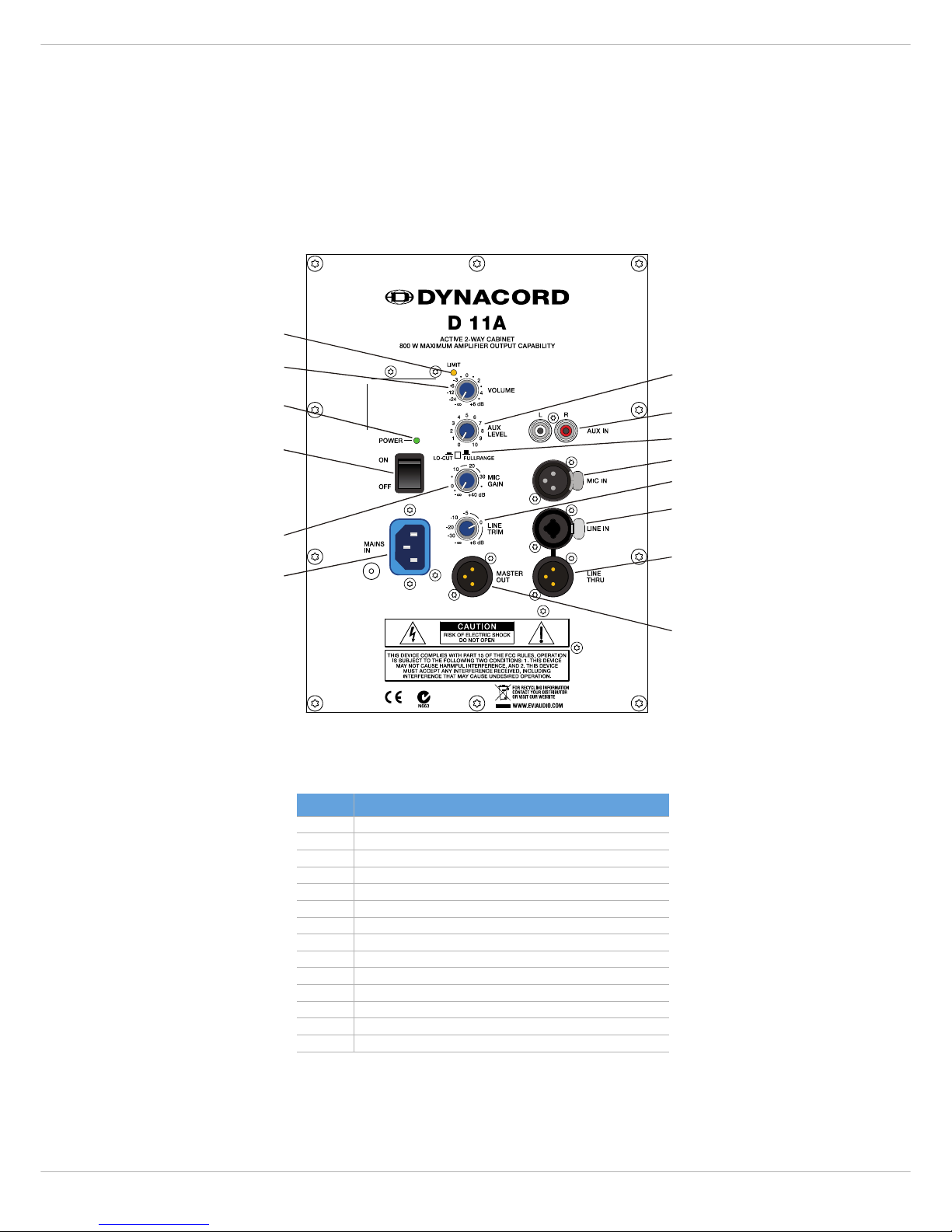
1 LIMIT INDICATOR (LIMIT)
Brief blinking of the LIMIT LED indicates that the
power amplifier of the D 11A is operated at its limits.
Short-term blinking is uncritical, because the inte-
grated limiter compensates minor distortion. Constant
lighting of the LED indicates that the sound is negatively af-
fected. Reducing the output volume is strongly recom-
mended.
2 MASTER LEVEL CONTROL (VOLUME)
Level control for adjusting the power
amp’s overall amplification.
3 POWER ON/OFF INDICATOR (POWER)
The POWER LED lights green if the mains
switch is ON and the mains cord is connect-
ed correctly.
4 MAINS SWITCH (ON/OFF)
Mains switch for switching the unit‘s power
ON or OFF. The POWER LED lights after
turning the power ON. Make sure that the
mains cord is correctly connected if the
LED is not lit upon switching the power on.
If the mains cord is correctly connected,
mains voltage is present and the LED does not light upon
power-on, please contact your local dealer.
5 MICROPHONE LEVEL CONTROL (MIC GAIN)
Level control for adjusting the amplifica-
tion of the signal at the MIC IN input.
6 MAINS CONNECTOR, LOCKABLE (MAINS IN)
The D 11A receives its power supply
via the lockable MAINS IN connector.
Only the provided power cord may be
used. Connect the D 11A only to a
mains network, which corresponds
to the requirements indicated on the
type plate. Press the yellow button at
the plug to disconnect the power
cord.
CAUTION: This applicance has no user-servicable parts
inside. Leave any servicing and maintenance
to qualified service technicians only.
7 AUX LEVEL CONTROL (AUX LEVEL)
This control is used to adjust the input
level of the signal source that is con-
nected to AUX IN L / R input.
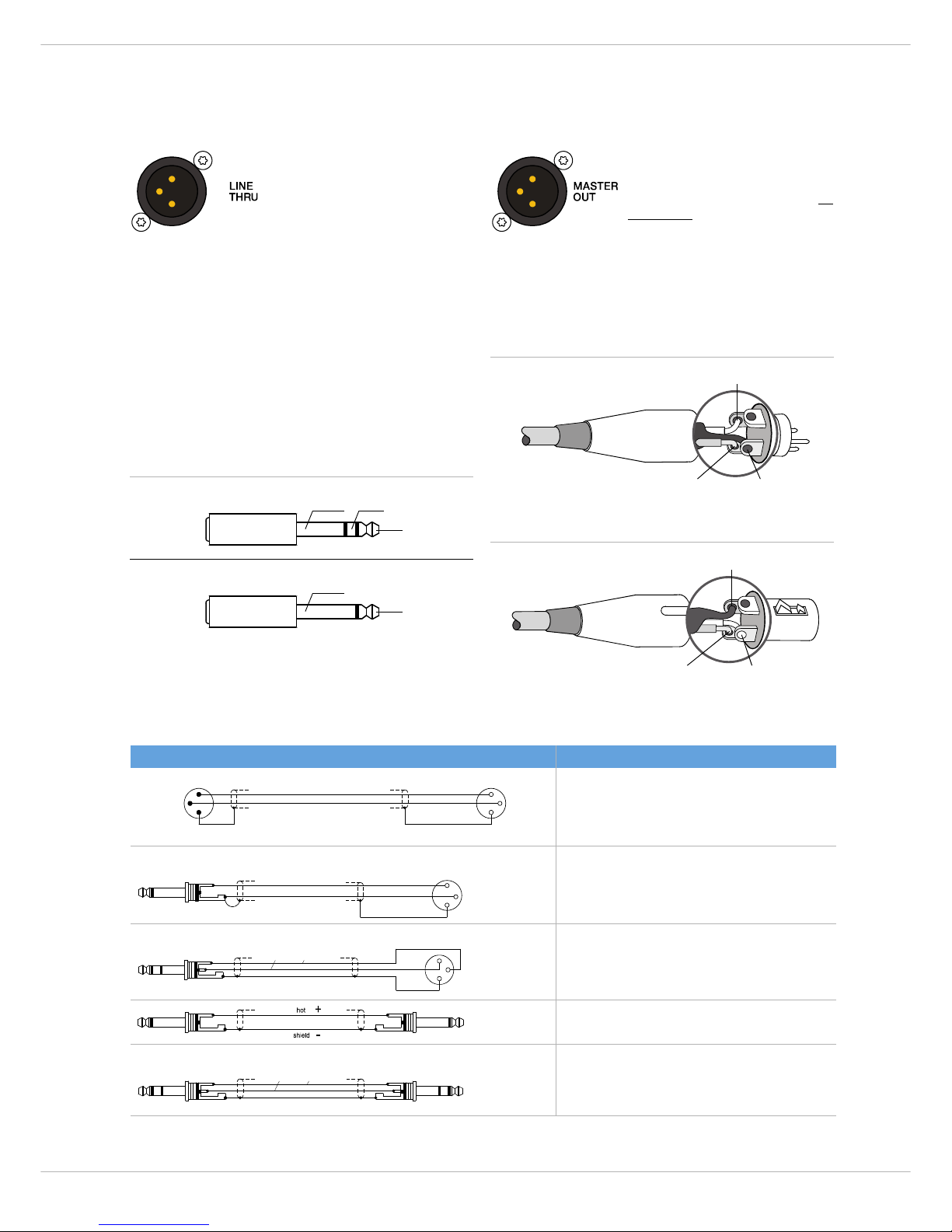
8 INPUT CONNECTOR FOR STEREO AUX SIGNAL (AUX IN L / R)
These RCA-type connectors allow
the connection of stereo signal
sources (e. g. CD-Player). The
stereo input signals are internally
summed for monaural output.
CAUTION: Before connecting or unplugging an appli-
ance, make sure to turn the AUX LEVEL con-
trol all the way down (counterclockwise).
9 MODE SELECTION SWITCH (LO-CUT/FULLRANGE)
If the D 11A is used as a fullrange sys-
tem, select FULLRANGE (button not
pressed). If a subwoofer is available, select LO-CUT (but-
ton pressed) for activating the internal low-cut filter. The
setting LO-CUT can also be used for monitor or delay ap-
plications, when a high bass level is not necessary.
10 INPUT CONNECTOR FOR MICROPHONE AUDIO SIGNAL (MIC
IN)
MIC IN is an electronically bal-
anced XLR-type input for connect-
ing low-impedance microphones.
CAUTION: Before making any connections or discon-
nections, make sure to set the MIC GAIN
level control to the counterclockwise stop.
Extremely high volume settings may result
in unpleasing feedback noise.
11 LINE LEVEL CONTROL (LINE TRIM)
Level control for adjusting the amplifica-
tion of the signal at the LINE IN input.
12 INPUT CONNECTOR FOR AUDIO SIGNAL (LINE IN)
LINE IN is an electronically bal-
anced input for connecting high-
impedance audio signal sources
like mixers, electronic music in-
struments like keyboards, guitars
and bass guitars with built-in ac-
tive electronics. It is possible to
connect balanced as well as unbalanced gear at the LINE
IN input using an monaural or stereo phone plug cable or
XLR-type plug cable. Balanced connection is preferable
whenever the source unit has a balanced output stage. Fol-
lowing this advice will provide you with the advantage of
less interference that is introduced from external hum or
HF-induction.
CAUTION: Before making any connections or discon-
nections, make sure to set the level control
to the counterclockwise stop.
LO-CUT

D 11A
7
13 OUTPUT CONNECTOR FOR AUDIO SIGNAL (LINE THRU)
This electronically balanced output
provides the carried through audio
signal from the LINE IN connector.
It can be used to feed additional
external equipment (e.g. an addi-
tional D 11A) with the identical in-
put signal.
14 OUTPUT CONNECTOR (MASTER OUT)
The output connector provides the
Master Signal (Line+Mic+Aux) for
”carrying through“ the input signal.
The level of the output signal is in-
dependent of the setting of the
Master level control (”Pre Fader”).
2.2 Cabling
For connecting audio signal sources to the D 11A, we rec-
ommend using cable with balanced XLR-type or stereo
phone plug connectors. Using balanced cable reduces the
risk of sound degradation resulting from interference.
However, make sure to mind the pin-assignment as shown
below. Original DYNACORD cable from our accessory pro-
gram will always comply with this pin-assignment.
Illustration 2-1: Balanced and unbalanced phone plug
BALANCED
SHIELD COLD
HOT
UNBALANCED
SHIELD
HOT
Illustration 2-2: Balanced XLR male
Illustration 2-3: Balanced XLR female
1, SHIELD
3, COLD
2, HOT
1, SHIELD
2, HOT
3, COLD
Cable Application
balanced connection of microphones
unbalanced external equipment with XLR-type in/output jacks
balanced external equipment with XLR-type in/output jacks
unbalanced external equipment with phone jack in/output jacks
balanced external equipment with phone jack in/output jacks
2
3
1
1
3
2
2 HOT (+)
1 SHIELD
3 COLD (-)
2 HOT (+)
1 SHIELD
3 COLD (-)
-
+
cold
hot
shield
13
2
Cable connection phone to XLR-type, unbalanced
2
3
1
+
hot cold
-
shield
Cable connection phone to XLR-type, balanced
+
hot cold
-
shield
Standard phone-type, balanced

DYNACORD
8
2.3 Cooling
This is a powered speaker with a very high efficient amp-
lifier module and as a result does not get really hot. The
temperature of the amplifier module is monitored. In the
rare event it does get too hot it will automatically shut
down to protect itself. Once its temperature has returned
to within its operating range the amp will turn back on.
This may happen when the speaker is operated in very high
ambient temperatures and the enclosure is exposed to di-
rect sunlight. Always ensure adequate cooling and appro-
priate shade to keep the ambient temperature around the
product within the specified operating temperature range.
2.4 Quick Start
CAUTION: After installing the system, first switch on the mixing console and position the mixer’s master faders to
their minimum settings. That followed, switch on the D 11A and use the master faders to adjust the
desired volume setting. Otherwise, high sound levels caused by unintentional playback of a program
source could be the result, which might cause hearing damage.
This Quick Start Manual outlines setup and operation of
the D 11A connected to a DYNACORD CMS mixer.
1. Place the D 11A, mounted on pole-mount stands to
the left and to the right. The lower edges of the
speaker systems should be approximately 1,8 meters
above the audience to provide sufficient coverage
and to prevent that listeners nearby are subject to
extreme sound levels.
2. Using suitable XLR-type cables connect the Master
Outputs of your mixing console, e.g. DYNACORD
CMS 1000, to LINE IN of the D 11A. Position the mas-
ter faders on the mixer to their minimum setting.
Now, switch on the mixer.
3. Connect the D 11A to the mains outlet using the sup-
plied mains cord. Plug the connector into the MAINS
IN socket. Use the Mains switch to power-up the
D11A.
4. Set the level controls VOLUME and LINE TRIM of the
D11Ato0dB.
5. Connect an audio source, e.g. CD player, to a line
level input of the mixer, e.g. CMS 1000. Set all rotary
controls of the mixing console input channel to their
center position. Adjust the input channel’s ‘Gain‘
control so that the Peak LED should not light at all or
blink only once in a while.
6. Slowly raise channel fader and master faders on the
mixing console to the desired positions – i.e. volume
settings.
7. Your system is now ready for operation. Individual
sound adjustments necessary can be made using the
controls of the mixer’s corresponding input chan-
nels.
8. Now, have fun with your D 11A system!
9. After use, first switch off the D 11A and then the mix-
ing console, so that distracting power-off noise will
not occur. When using a DYNACORD CMS mixer, no
power-off noise will be output from the ‘Master Out-
puts‘. This allows switching off the mixer first with-
out a problem.

D 11A
9
2.5 Rigging
CAUTION: We expressly point out that the relevant safety regulations must be observed for “flying“ loudspeaker
systems. It is imperative that qualified expert advice is sought.
CAUTION: Suspending any object is potentially dangerous and should only be attempted by individuals who have
a thorough knowledge of the techniques and regulations of rigging objects overhead. DYNACORD
strongly recommends that D 11A speakers be suspended taking into account all current national, fed-
eral, state and local regulations. It is the responsibility of the installer to ensure that D 11A speakers
are safely installed in accordance with all such regulations. If D 11A speakers are suspended, DYNA-
CORD strongly recommends that the system be inspected at least once a year. If any sign of weakness
or damage is detected, remedial action should be taken immediately.
Order No. see Specifications (page 26)
MB-200 UMH
MB-200 UMH
+ RMA +TMA
MB312
MB112
MB-200 UMH
+ TC-02
F212

DYNACORD
10
1) MB 112 must only be used together with MB 212 due to safety reasons.
Property D 11A 230 Volt D 11A 120 Volt
Order No. F01U135396 (D113301) F01U135397 (D113302)
Cabinet Powered Full-Range 2-Way
Maximum Amplifier Output Capability 800 Watts
Lo Amplifier Power RMS 200 Watts
Mid-High Amplifier Power RMS 200 Watts
Max. SPL 1 m/calc 126 dB
Frequency Range (-10 dB) 48 Hz to 20 kHz
Nominal Coverage Angle (Horizontal x Vertical) 80° x 40°
X-Over Frequency 1.2 kHz
LF Transducer LFT3508
HF Transducer DH 3
Switchable Lo-Cut 120 Hz, 12 dB/Oct
Power Requirement 220 to 240 V AC, 0.6 A, 50 to 60 Hz 100 to 120 V AC, 1.1 A, 50 to 60 Hz
Operating Temperature Range 0 °C to 40 °C
Dimensions (W x H x D) 429.5 mm x 586 mm x 320.5 mm (16.90” x 23.07” x 12.55”)
Net Weight 15.3 kg
Shipping Weight 18.3 kg
Enclosure material Heavy Duty Polypropylene
Finish Black
Grille Powder coated steel, Acoustic foam
Handles 1
Warranty 36 months
Optional Accessories
SH-D12 Dust Cover F01U118994 (D113046)
F 212 Monitor feet F01U100802 (D113040)
MB 112 Eyebolt-Set M8 1) F01U100803 (D113041)
MB 212 U-Mounting Bracket F01U100804 (D113042)
MB 312 Horizontal Cluster Plate F01U100805 (D113043)
MB 200 UMH U-Bracket F01U120157 (D170183)
TMA Tilt angle for UMH F01U118977 (D112815)
RMA Rotatable Mounting Kit F01U118976 (D112807)
TC-02 Truss clamp F01U100657 (D112808)
Spare Parts
Mains Cord (5 meters) F01U108377 (D368217) F01U105973 (D362222)
LF Transducer F01U107290 (D366023)
HF Transducer F01U103119 (D353078)

D11A
11
WICHTIGE SICHERHEITSHINWEISE
1. Lesen Sie diese Hinweise.
2. Heben Sie diese Hinweise auf.
3. Beachten Sie alle Warnungen.
4. Richten Sie sich nach den Anweisungen.
5. Betreiben Sie das Gerät nicht in unmittelbarer Nähe von Wasser.
6. Verwenden Sie zum Reinigen des Gerätes ausschließlich ein trockenes Tuch.
7. Verdecken Sie keine Lüftungsschlitze. Beachten Sie bei der Installation des Gerätes stets die entsprechenden Hinweise des Herstellers.
8. Vermeiden Sie die Installation des Gerätes in der Nähe von Heizkörpern, Wärmespeichern, Öfen oder anderer Wärmequellen.
9. Achtung: Gerät nur an Netzsteckdose mit Schutzleiteranschluss betreiben. Setzen Sie die Funktion des Schutzleiteranschlusses des
mitgelieferten Netzanschlusskabels nicht außer Kraft. Sollte der Stecker des mitgelieferten Kabels nicht in Ihre Netzsteckdose passen, setzen
Sie sich mit Ihrem Elektriker in Verbindung.
10. Sorgen Sie dafür, dass das Netzkabel nicht betreten wird. Schützen Sie das Netzkabel vor Quetschungen insbesondere am Gerätestecker und
am Netzstecker.
11. Verwenden Sie mit dem Gerät ausschließlich Zubehör/Erweiterungen, die vom Hersteller hierzu vorgesehen sind.
12. Verwenden Sie zusammen mit dieser Komponente nur vom Hersteller dazu vorgesehene oder andere geeignete Lastkarren,
Stative, Befestigungsklammern oder Tische, die Sie zusammen mit dem Gerät erworben haben. Achten Sie beim Transport mittels
Lastkarren darauf, dass das transportierte Equipment und der Karren nicht umfallen und möglicherweise Personen- und/oder
Sachschäden verursachen können.
13. Ziehen Sie bei Blitzschlaggefahr oder bei längerem Nichtgebrauch den Netzstecker.
14. Überlassen Sie sämtliche Servicearbeiten und Reparaturen einem ausgebildeten Kundendiensttechniker. Servicearbeiten sind
notwendig, sobald das Gerät auf irgendeine Weise beschädigt wurde, wie z.B. eine Beschädigung des Netzkabels oder des Netzsteckers, wenn
eine Flüssigkeit in das Gerät geschüttet wurde oder ein Gegenstand in das Gerät gefallen ist, wenn das Gerät Regen oder Feuchtigkeit
ausgesetzt wurde, oder wenn es nicht normal arbeitet oder fallengelassen wurde.
15. Stellen Sie bitte sicher, dass kein Tropf- oder Spritzwasser ins Geräteinnere eindringen kann. Platzieren Sie keine mit Flüssigkeiten gefüllten
Objekte, wie Vasen oder Trinkgefäße, auf dem Gerät.
16. Um das Gerät komplett spannungsfrei zu schalten, muss der Netzstecker gezogen werden.
17. Beim Einbau des Gerätes ist zu beachten, dass der Netzstecker leicht zugänglich bleibt.
18. Stellen Sie keine offenen Brandquellen, wie z.B. brennende Kerzen auf das Gerät.
19. Dieses SCHUTZKLASSE I Gerät muss an eine NETZ-Steckdose mit Schutzleiter-Anschluss angeschlossen werden.
WICHTIGE SERVICEHINWEISE
ACHTUNG: Diese Servicehinweise sind ausschließlich zur Verwendung durch qualifiziertes Servicepersonal. Um die Gefahr
eines elektrischen Schlages zu vermeiden, führen Sie keine Wartungsarbeiten durch, die nicht in der
Bedienungsanleitung beschrieben sind, außer Sie sind hierfür qualifiziert. Überlassen Sie sämtliche
Servicearbeiten und Reparaturen einem ausgebildeten Kundendiensttechniker.
1. Bei Reparaturarbeiten im Gerät sind die Sicherheitsbestimmungen nach EN 60065 (VDE 0860) einzuhalten.
2. Bei allen Arbeiten, bei denen das geöffnete Gerät mit Netzspannung verbunden ist und betrieben wird, ist ein Netz-Trenntransformator zu
verwenden.
3. Vor einem Umbau mit Nachrüstsätzen, Umschaltung der Netzspannung oder sonstigen Modifikationen ist das Gerät stromlos zu schalten.
4. Die Mindestabstände zwischen netzspannungsführenden Teilen und berührbaren Metallteilen (Metallgehäuse) bzw. zwischen den Netzpolen
betragen 3 mm und sind unbedingt einzuhalten.
5. Die Mindestabstände zwischen netzspannungsführenden Teilen und Schaltungsteilen, die nicht mit dem Netz verbunden sind (sekundär),
betragen 6 mm und sind unbedingt einzuhalten.
6. Spezielle Bauteile, die im Stromlaufplan mit dem Sicherheitssymbol gekennzeichnet sind, (Note) dürfen nur durch Originalteile ersetzt werden.
7. Eigenmächtige Schaltungsänderungen dürfen nicht vorgenommen werden.
8. Die am Reparaturort gültigen Schutzbestimmungen der Berufsgenossenschaften sind einzuhalten. Hierzu gehört auch die Beschaffenheit des
Arbeitsplatzes.
9. Die Vorschriften im Umgang mit MOS-Bauteilen sind zu beachten.
Hinweise zur Entsorgung/Wiederverwendung gemäß WEEE
Das auf unserem Produkt und im Handbuch abgedruckte Mülltonnensymbol weist daraufhin, dass dieses Produkt nicht gemeinsam mit dem Haushaltsmüll entsorgt werden darf. Für
die korrekte Entsorgung der Elektro- und Elektronik-Altgeräte (WEEE) am Ende ihrer Nutzungsdauer ist in unserer Kategorie der Hersteller verantwortlich. Aufgrund
unterschiedlicher Regelungen zur WEEE-Umsetzung in den einzelnen EU-Staaten bitten wir Sie, sich an Ihren örtlichen Händler zu wenden. Wir haben ein eigenes System zur
Verarbeitung elektronischer Abfälle und gewährleisten die kostenfreie Entgegennahme aller Produkte der EVI Audio GmbH: Telex, DYNACORD, Electro-Voice und RTS. Wir haben mit
dem Händler, bei dem Sie Ihr Produkt gekauft haben, eine Vereinbarung getroffen, dass alle nicht mehr verwenbaren Geräte zur umweltgerechten Entsorgung
kostenfrei
an das Werk
in Straubing zurückgeschickt werden.
Das Blitzsymbol innerhalb eines gleichseitigen
Dreiecks soll den Anwender auf nicht isolierte Lei-
tungen und Kontakte im Geräteinneren hinweisen,
an denen hohe Spannungen anliegen, die im Fall
einer Berührung zu lebensgefährlichen Strom-
schlägen führen können.
Das Ausrufezeichen innerhalb eines gleichseitigen
Dreiecks soll den Anwender auf wichtige Bedie-
nungs- sowie Servicehinweise in der zum Gerät
gehörenden Literatur aufmerksam machen.
NOTE: SAFETY COMPONENT (MUST BE REPLACED BY ORIGINAL PART)

DYNACORD
12
1 Einführung
Die DYNACORD D 11A ist ein extrem leichtes, mechanisch
robustes, aktives 12“ 2-Weg Fullrange-Kunststoffkabinett
mit eingebauten Leistungsendstufen für professionelle Be-
schallungsanwendungen. Umfangreiches Montagezubehör
und eine zurückhaltende optische Gestaltung des
Kabinetts ermöglichen den problemlosen Einsatz auch in
kritischen Anwendungen für Festinstallationen. Das
Gehäuse ist aus Polypropylen gefertigt und widersteht här-
testen Anforderungen bei Transport und Einsatz. Die
D 11A ist mit dem LFT3508 Lautsprecher für den Bass- und
Mittenbereich ausgestattet. Das Constant Directivity
Hochtonhorn mit nominalen Abstrahlwinkeln von 80° * 40°
(Horizontal * Vertikal) ist CAD-optimiert in die Schallwand
integriert und mit dem hochbelastbaren Electro-Voice
DH 3 ausgestattet.
Die eingebauten Digitalendstufen arbeiten im Aktiv-2-Weg
Betrieb und werden von einer speziell auf die Laut-
sprecherkomponenten ausgelegten elektronischen Fre-
quenzweiche angesteuert. Mit einem Maximalschallpegel
von 126 dB (1 kHz, k = 10%) und einem Übertragungsbe-
reich von 48 Hz bis 20 kHz eignet sich die D 11A hervor-
ragend sowohl als Fullrange-Kabinett als auch als Mittel-
Hochtonteil in Satellitensystemen. Die aktive Frequenz-
weiche ist auf große Reichweite bei gleichmäßiger
Abstrahlcharakteristik hin optimiert und gestattet den
Einsatz der D 11A auch unter ungünstigen akustischen
Umgebungsbedingungen. Mit den EASE und Ulysses Da-
tenfiles sind problemlos auch anspruchsvollste Simulati-
onen schnell und präzise durchführbar.
Durch die vielfältigen Anschluss- und Einstellmög-
lichkeiten (MIC, LINE und AUX) werden Ihrer Kreativität
keine Grenzen gesetzt. Das Gesamtsignal kann über ein
XLR-Kabel auf weitere D 11A Boxen weitergeschleift wer-
den. Der Pegelregler VOLUME gestattet eine einfache
Lautstärkeanpassung des widergegebenen Gesamtsignals.
Die D 11A wird über einen verriegelnden Stecker an das
Stromnetz angeschlossen. Die Frontabdeckung ist in
schwarzem Akustikschaum auf einem robusten, pulverbe-
schichtetem Stahlgitter ausgeführt. Mit einem umfang-
reichen Montagezubehör kann die D 11A problemlos für
unterschiedlichste Anforderungen optimal ausgestattet
werden. Als Zubehör ist eine robuste, strapazierfähige und
wasserabweisende Schutzhülle erhältlich. Das abge-
schrägte Gehäuse und die als Sonderzubehör erhältlichen
Schrägsteller erlauben den problemlosen Einsatz auch in
Monitorapplikationen bei denen ein im Vergleich zu typi-
schen Monitorlautsprechern erweiterter Bassbereich
gefordert ist. Ein stabiler Tragegriff und der eingebaute
Hochständer-Einsatz ermöglichen einen bequemen
Transport und optimale Aufstellung zum Publikum.
1.1 Lieferumfang, Auspacken und
Überprüfen
Öffnen Sie die Verpackung und entnehmen Sie das
Kabinett. Überprüfen Sie das Kabinett auf äußere Be-
schädigungen, die während des Transports zu Ihnen aufge-
treten sein könnten. Jedes Kabinett wird vor Verlassen des
Werks eingehend untersucht und getestet und sollte in ein-
wandfreiem Zustand bei Ihnen ankommen. Falls das
Kabinett Beschädigungen aufweist, benachrichtigen Sie
bitte unverzüglich das Transportunternehmen. Ein
Transportschaden kann nur von Ihnen, dem Empfänger,
reklamiert werden. Bewahren Sie den Karton und das Ver-
packungsmaterial zwecks Besichtigung durch das
Transportunternehmen auf. Die Aufbewahrung des Kar-
tons samt Verpackungsmaterial wird auch dann angeraten,
wenn das Kabinett keine Beschädigung aufweist.
ACHTUNG: Versenden Sie das Kabinett nie ohne das
originale Verpackungsmaterial.
Wenn Sie das Kabinett versenden, verwenden Sie stets
den Originalkarton und das originale Verpackungsmaterial.
Für bestmöglichen Schutz vor Transportschäden verpak-
ken Sie das Kabinett wie es ursprünglich im Werk verpackt
wurde.
1.2 Garantie
Hinweise zur Garantie finden Sie auf www.dynacord.com
•1AktivesKabinett
• 1 Bedienungsanleitung (dieses Dokument)
• 1 Netzkabel (verriegelnd, 5 Meter)
• 1 Garantiekarte mit Sicherheitshinweisen

D 11A
13
2 Installation
2.1 Bedienelemente, Anzeigen und Anschlüsse
3
4
6
7
8
9
11
12
13
1
2
5
10
14
Nummer Beschreibung
1Anzeige Limiter (LIMIT)
2Lautstärke-Regler (VOLUME)
3Anzeige Betrieb (POWER)
4Netzschalter (ON / OFF)
5Mikrofonpegel-Regler (MIC GAIN)
6Netzeingang, verriegelnd (MAINS IN)
7AUX-Pegel-Regler (AUX LEVEL)
8Stereo-Eingang (Cinch) für AUX-Audio-Signal (AUX IN L/R)
9Schalter für Betriebsart (LO-CUT / FULLRANGE)
10 Eingang für Audio-Signal mit Mikrofon-Pegel (MIC IN)
11 Eingangspegel-Regler für Line-Eingang (LINE TRIM)
12 Eingang (XLR/Klinke) für Audio-Signal mit Line-Pegel (LINE IN)
13 Ausgang (XLR) für Audio-Signal mit Line-Pegel (LINE THRU)
14 Ausgang (XLR) für (gemischtes) Audio-Signal mit Line-Pegel (MASTER OUT)

DYNACORD
14
1 ANZEIGE LIMITER (LIMIT)
Die LIMIT-LED zeigt beim Aufleuchten an, dass der in-
terne Leistungsverstärker aktuell im Grenzbereich
der Aussteuerbarkeit betrieben wird. Kurzzeitiges
Aufleuchten ist unkritisch, da der Audio-Limiter im Leis-
tungsverstärker die Verzerrungen ausregelt. Dauerndes
Aufleuchten deutet auf eine Übersteuerung des Verstär-
kers hin, die zu Klangeinbußen führen kann und durch Ab-
senkung des Eingangspegels vermieden werden sollte.
2 LAUTSTÄRKE-REGLER (VOLUME)
Mit diesem Regler stellen Sie die
Lautstärke der D 11A ein. Zur Ver-
meidung von Verzerrungen in vorge-
schalteten Mischpulten sollte dieser
Regler normalerweise zwischen 0 dB
und +6 dB eingestellt werden.
3 ANZEIGE BETRIEB (POWER)
Die POWER-LED leuchtet grün, wenn die
D 11A mit dem Stromnetz verbunden und
eingeschaltet (ON) ist.
4 NETZSCHALTER (ON/OFF)
Netzschalter zum Ein- und Ausschalten des
Gerätes. Die POWER-LED leuchtet grün
wenn die D 11A eingeschaltet ist. Sollte die
LED nach dem Einschalten nicht leuchten,
prüfen Sie zuerst ob das Netzkabel ange-
steckt und Netzspannung vorhanden ist. Ist
dies der Fall und trotzdem keine Funktion vorhanden,
kontaktieren Sie bitte ihren Fachhändler.
5 MIKROFONPEGEL-REGLER (MIC GAIN)
Mit diesem Regler passen Sie die Laut-
stärke des Mikrofon-Signals an. Der Ein-
stellbereich erstreckt sich dabei von
-∞dB bis +40 dB.
6 NETZEINGANG (MAINS)
Die Spannungsversorgung der D 11A
erfolgt ausschließlich über das mit-
gelieferte IEC-Netzkabel über diese
verriegelnde Netzbuchse. Zum
Abziehen des Steckers drücken Sie
die gelbe Verriegelungs-Taste am
Stecker. Schließen Sie die D 11A nur
an eine geeignete Netzversorgung an,
die den auf dem Typenschild angegebenen Anforderungen
entspricht.
7 AUX-PEGEL-REGLER (AUX LEVEL)
Mit diesem Regler passen Sie die Laut-
stärke des am AUX IN angeschlossenen
Signals ein.
8 EINGANG FÜR AUX-SIGNAL (AUX IN L/R)
Sie können an den Cinch-Buch-
sen Stereo-Signalquellen (z. B.
CD-Player) anschließen. Die Si-
gnale für den rechten und linken
Kanal werden intern summiert.
ACHTUNG: Drehen Sie vor dem An- und Abstecken an
den Eingängen den AUX LEVEL-Regler auf
Linksanschlag.
9 SCHALTER FÜR DIE BETRIEBSART (LO-CUT/FULLRANGE)
Wählen Sie die Schalterstellung
FULLRANGE (Schalter nicht
gedrückt) wenn die D 11A ohne Subwoofer betrieben
wird. Wird ein zusätzlicher Subwoofer verwendet aktivie-
ren Sie das interne Hochpass-Filter der D 11A durch Wahl
der Schalterstellung LO-CUT (Schalter gedrückt). Die
Schalterstellung LO-CUT ist auch für Monitor- und Delay-
Anwendungen geeignet, wenn kein hoher Bass-Pegel benö-
tigt wird.
10 EINGANG FÜR MIKROFON-SIGNAL (MIC IN)
Elektronisch symmetrischer XLR-
Eingang zum Anschluss
niederohmiger Mikrofone.
ACHTUNG: Drehen Sie vor dem An- und Abstecken an
den Eingängen den MIC GAIN-Regler auf
Linksanschlag.
11 EINGANGSPEGEL-REGLER FÜR LINE-EINGANG (LINE TRIM)
Mit diesem Regler passen Sie die Laut-
stärke des am LINE IN angeschlossenen
Signals ein. Der Einstellbereich er-
streckt sich dabei von -∞dB bis +6 dB.
12 EINGANG FÜR LINE-SIGNAL (LINE IN)
Elektronisch symmetrischer
Eingang für hochpegelige Signal-
quellen wie Mischpulte, Signal-
prozessoren oder elektronische
Instrumente wie Keyboard, Gitar-
ren und Bässe mit aktiver Elektro-
nik. Der LINE IN Eingang kann
sowohl symmetrisch als auch unsymmetrisch gespeist
werden. Der Anschluss kann dabei wahlweise über Mono-
bzw. Stereoklinken- oder XLR-Stecker vorgenommen wer-
den. Um etwaigen externen Brumm-, oder Hochfrequenz-
einstreuungen vorzubeugen, sollte die Signaleinspeisung,
wenn möglich, symmetrisch erfolgen.
ACHTUNG: Drehen Sie vor dem An- und Abstecken an
den Eingängen den LINE TRIM-Regler auf
Linksanschlag.
LO-CUT

D 11A
15
13 AUSGANG FÜR LINE-SIGNAL (LINE THRU)
An der LINE THRU-Buchse liegt das
Signal der LINE IN-Buchse an. Ver-
wenden Sie diesen Ausgang um
das Signal an weitere Geräte mit
LINE-Eingängen durchzuschleifen
(z.B. zusätzliche D 11A).
14 AUSGANG FÜR GEMISCHTES AUDIO-SIGNAL (MASTER OUT)
Am Ausgang MASTER OUT liegt das
gemischte Signal des AUX-, MIC-
und LINE-Eingangs zum „Weiter-
schleifen” an. Der Pegel des Si-
gnals hängt nicht von der Stellung
des Lautstärke-Regler VOLUME ab
(„Pre Fader“).
2.2 Verkabelung
Zum Anschluss Ihrer Signalquellen sollten Sie nach Mög-
lichkeit symmetrisch ausgelegte Kabel mit XLR- oder Ste-
reoklinken-Stecker verwenden. Die symmetrische
Verkabelung reduziert in hohem Maße Probleme durch
Einstreuung von Störgeräuschen. Achten Sie auf jeden Fall
auf die nachfolgend abgebildete Anschlussbelegung der
Steckverbinder. Kabel aus dem DYNACORD Zubehörsor-
timent werden in jedem Fall dieser Belegung entsprechen.
Abbildung 2-1: Symmetrische bzw. unsymmetrische Belegung
des Klinkenstecker
BALANCED
SHIELD COLD
HOT
UNBALANCED
SHIELD
HOT
Abbildung 2-2: Symmetrische Belegung von XLR male
Abbildung 2-3: Symmetrische Belegung von XLR female
1, SHIELD
3, COLD
2, HOT
1, SHIELD
2, HOT
3, COLD
Kabel Anwendung
Mikrofone symmetrisch
Externe Geräte mit unsymmetrischer XLR Ein- bzw. Ausgangs-
buchse
Externe Geräte mit symmetrischer XLR Ein- bzw. Ausgangs-
buchse
Externe Geräte mit unsymmetrischer Klinken-Ein- bzw. Aus-
gangsbuchse
Externe Geräte mit symmetrischer Klinken-Ein- bzw. Ausgangs-
buchse
2
3
1
1
3
2
2 HOT (+)
1 SHIELD
3 COLD (-)
2 HOT (+)
1 SHIELD
3 COLD (-)
-
+
cold
hot
shield
13
2
Cable connection phone to XLR-type, unbalanced
2
3
1
+
hot cold
-
shield
Cable connection phone to XLR-type, balanced
+
hot cold
-
shield
Standard phone-type, balanced

DYNACORD
16
2.3 Kühlung
Das in der D 11A integrierte Endstufenmodul hat einen
sehr hohen Wirkungsgrad, daher ist die Wärmeent-
wicklung sehr gering. Wird die zulässige Betriebstem-
peratur der Endstufe überschritten, schaltet die
integrierte Temperaturüberwachung das Modul ab. Sobald
die Temperatur wieder im normalen Betriebsbereich liegt
geht die Endstufe automatisch wieder in Betrieb. Zur
Abschaltung kommt es normalerweise nur bei sehr hoher
Umgebungstemperatur und direkter Sonneneinstrahlung.
Sorgen Sie daher während des Betriebs der D 11A für die
Einhaltung der spezifizierten Umgebungstemperatur um
ein Abschalten zu verhindern.
2.4 Quickstart
ACHTUNG: Nach dem Aufbau der Anlage schalten Sie zuerst das Mischpult ein und schieben Sie die Masterfader
am Mischpult auf den untereren Anschlag. Anschliessend können Sie die D 11A einschalten und mit
dem Masterfader die gewünschte Lautstärke einstellen. Ansonsten können Sie ungewollt bei einge-
schalteter Signalquelle sehr hohen Schallpegeln ausgesetzt werden, die zu Gehörschädigungen führen
können.
Diese Quickstart-Anleitung erklärt Aufbau und Betrieb von
D 11A Kabinetten mit einem DYNACORD CMS Mischpult.
1. Stellen Sie die D 11A links und rechts auf Hoch-
ständer. Die Boxenunterkanten sollten in etwa 1,80
Meter Höhe über dem Publikum sein, um eine
genügende Reichweite zu erzielen und die in der
Nähe befindlichen Zuhörer vor zu hohen Schallpegeln
zu schützen.
2. Verbinden Sie die Master Outputs Ihres Mischpultes,
z. B. DYNACORD CMS 1000, mit geeigneten XLR
Kabeln mit der Buchse LINE IN der D 11A und
schieben Sie die Masterfader am Mischpult auf den
unteren Anschlag. Schalten Sie nun das Mischpult
ein.
3. Sie können nun die D 11A mit dem beiliegenden
Netzkabel an das Stromnetz anschliessen. Der Stek-
ker wird hierzu in die Buchse MAINS IN gesteckt bis
der Stecker hör- und spürbar verriegelt. Mit dem
Netzschalter setzen Sie die D 11A in Betrieb (ON).
4. Stellen Sie die Lautstärke-Regler VOLUME und LINE
TRIM der D 11A auf 0dB.
5. Schliessen Sie nun eine Audio-Quelle, z. B. einen CD-
Player, an einen LINE-Kanal Ihres Mischpultes, z. B.
CMS 1000, an. Justieren Sie den Gain-Regler des
Eingangskanals des Mischpults so, dass die Peak-
LED im Kanal nicht oder nur gelegentlich aufleuchtet.
6. Sie können nun den Kanalfader und die Masterfader
am Mischpult langsam auf die gewünschte Lautstärke
„hochfahren”.
7. Ihre Anlage ist damit betriebsbereit und Sie können
individuell notwendige klangliche Korrekturen in den
Eingangskanälen des Mischpultes justieren.
8. Viel Spass beim Arbeiten mit Ihrer D 11A Anlage!
9. Nach Benutzung schalten Sie zuerst die D 11A und
anschliessend Ihr Mischpult aus. Störende Abschalt-
geräusche können dann nicht auftreten. Bei Ver-
wendung eines DYNACORD CMS Mischpultes treten
an den ‚Master Outputs‘ keinerlei Abschaltgeräusche
auf, hier können Sie bedenkenlos auch das Mischpult
zuerst ausschalten.

D 11A
17
2.5 Rigging
ACHTUNG: Wir weisen ausdrücklich darauf hin, dass bei gehängten Lautsprecherboxen die einschlägigen Sicher-
heitsbestimmungen zu beachten sind. Es muss unbedingt qualifizierte Fachberatung in Anspruch
genommen werden!
Bestellnummern des Rigging-Zubehörs finden Sie auf siehe Seite 26.
MB-200 UMH
MB-200 UMH
+ RMA +TMA
MB312
MB112
MB-200 UMH
+ TC-02
F212

DYNACORD
18
1) MB 112 must only be used together with MB 212 due to safety reasons.
Property D 11A 230 Volt D 11A 120 Volt
Order No. F01U135396 (D113301) F01U135397 (D113302)
Cabinet Powered Full-Range 2-Way
Maximum Amplifier Output Capability 800 Watts
Lo Amplifier Power RMS 200 Watts
Mid-High Amplifier Power RMS 200 Watts
Max. SPL 1 m/calc 126 dB
Frequency Range (-10 dB) 48 Hz to 20 kHz
Nominal Coverage Angle (Horizontal x Vertical) 80° x 40°
X-Over Frequency 1.2 kHz
LF Transducer LFT3508
HF Transducer DH 3
Switchable Lo-Cut 120 Hz, 12 dB/Oct
Power Requirement 220 to 240 V AC, 0.6 A, 50 to 60 Hz 100 to 120 V AC, 1.1 A, 50 to 60 Hz
Operating Temperature Range 0 °C to 40 °C
Dimensions (W x H x D) 429.5 mm x 586 mm x 320.5 mm (16.90” x 23.07” x 12.55”)
Net Weight 15.3 kg
Shipping Weight 18.3 kg
Enclosure material Heavy Duty Polypropylene
Finish Black
Grille Powder coated steel, Acoustic foam
Handles 1
Warranty 36 months
Optional Accessories
SH-D12 Dust Cover F01U118994 (D113046)
F 212 Monitor feet F01U100802 (D113040)
MB 112 Eyebolt-Set M8 1) F01U100803 (D113041)
MB 212 U-Mounting Bracket F01U100804 (D113042)
MB 312 Horizontal Cluster Plate F01U100805 (D113043)
MB 200 UMH U-Bracket F01U120157 (D170183)
TMA Tilt angle for UMH F01U118977 (D112815)
RMA Rotatable Mounting Kit F01U118976 (D112807)
TC-02 Truss clamp F01U100657 (D112808)
Spare Parts
Mains Cord (5 meters) F01U108377 (D368217) F01U105973 (D362222)
LF Transducer F01U107290 (D366023)
HF Transducer F01U103119 (D353078)

D11A
19
IMPORTANT INFORMATIONS DE SÉCURITÉ
1. Lisez ces instructions.
2. Conservez ces instructions.
3. Tenez compte des avertissements.
4. Respectez toutes les instructions.
5. Ne pas utiliser cet appareil près d’un point d’eau.
6. Nettoyer uniquement à l’aide d’un chiffon sec.
7. Ne bloquez aucun des orifices de ventilation. Installez-le en respectant les instructions du fabricant.
8. Ne l’installez pas près de sources de chaleur telles que radiateurs, poêles, ou autres appareils produisant de la chaleur.
9. Utilisez uniquement les accessoires spécifiés par le fabricant.
10. Adressez-vous toujours à un personnel qualifié pour toutes les réparations. Une révision est nécessaire lorsque l’appareil a été
endommagé d’une manière quelconque: sa prise ou son cordon d’alimentation sont abimés, du liquide a été renversé ou des
objets sont tombés à l’intérieur, l’appareil a été exposé à la pluie ou à l’humidité, son fonctionnement est anormal ou il a subi
une chute.
11. Ne pas exposer cet appareil à la pluie ni aux éclaboussures et veiller à ce qu’aucun récipient, tel que vase, verre, etc., ne soit
posé sur cet appareil.
12. Pour déconnecter complètement cet appareil du secteur, il faut débrancher le cordon d’alimentation.
INSTRUCTIONS DE RÉPARATION IMPORTANTES
ATTENTION: Ces instructions de maintenance s’adressent uniquement à des techniciens qualifiés. Pour réduire le risque
d’électrocution, n’effectuez aucune opération de maintenance autre que celles contenues dans les instructions
d’utilisation, à moins d’être qualifié pour le faire. Confiez toutes ces interventions à un personnel qualifié.
1. Les règles de sécurité telles qu’elles sont spécifiées par les directives EN 60065 (VDE 0860 / IEC 65) et CSA E65 - 94 doivent
être observées lors de la réparation de l’appareil.
2. L’usage d’un transformateur d’isolation est obligatoire pendant la maintenance lorsque l’appareil est ouvert, qu’il doit fonctionner
et est branché sur le secteur.
3. Mettez hors tension avant de brancher toute extension, changer la tension secteur ou celle de sortie en fonction.
4. La distance minimum entre les éléments sous tension secteur et toute pièce de métal accessible (boîtier métallique), doit être
de 3 mm entre phase. Ceci doit être respecté en permanence. La distance minimum entre les éléments sous tension secteur et
tout commutateur ou interrupteur non connecté au secteur (éléments secondaires) doit être de 6 mm. Ceci doit être respecté en
permanence.
5. Le remplacement de composants spéciaux qui sont marqués d’un symbole de sécurité (Remarque) sur le schéma de principe
n’est autorisé qu’en utilisant des pièces d’origine.
6. La modification des circuits sans autorisation ou avis préalable n’est pas permise.
7. Toutes les règlementations concernant la sécurité du travail en vigueur dans le pays où l’appareil est réparé doivent être
strictement observées. Ceci s’applique également aux règlementations concernant le lieu de travail lui-même.
8. Toutes les instructions concernant la manipulation de circuits MOS doivent être respectées.
Gestion du REEE (recyclage des équipements électriques et électroniques) (applicable dans les états membres de l'Union
Européenne et autres pays Européens, avec des réglementations nationales spécifiques sur la gestion du REEE). Le sym-
bole apposé sur le produit ou sur son emballage indique que ce produit ne peut pas être traité comme un déchet domestique
normal, mais doit être conditionné et retourné à son revendeur d'origine.
Le symbole „éclair“ à l’intérieur d’un triangle
signale à l’utilisateur la présence dans
l’appareil de câbles et de contacts qui ne
sont pas isolés, dans lesquels circule un
courant électrique à haute tension, et qu’on
ne doit en aucun cas toucher afin d’éviter de
recevoir une décharge électrique qui pour-
rait être mortelle.
Le symbole „point d’exclamation“ à l’inté-
rieur d’un triangle signale à l’utilisateur les
consignes importantes concernant la main-
tenance et l’emploi de l’appareil, il vous
invite à lire le mode d’emploi accompagnant
cet appareil.
REMARQUE: COMPOSANT DE SÉCURITÉ (NE DOIT ÊTRE REMPLACÉ QUE PART UNE PIÈCE
D’ORIGINE)

DYNACORD
20
1 Introduction
La D 11A DYNACORD est une enceinte 12" 2 voies pleine
bande, bi-amplifiée, avec son alimentation. Légère mais ex-
trêmement robuste et de qualité professionnelle, présen-
tée dans une caisse en polypropylène moulé, elle est
destinée à un usage professionnel pour les applications
mobiles de sonorisation. Livrée avec une panoplie com-
plète d'équipements de fixation et les accessoires habi-
tuels, la D 11A est également idéale pour être utilisée dans
les installations fixes délicates. Comme cette enceinte est
en polypropylène, elle est extrêmement résistante aux
chocs qui ne manqueront pas de lui arriver pendant les
tournées. Pour les fréquences basses une LFT3508 sera
utilisée. Le moteur Electro-Voice DH 3 sert à la projection
des fréquences moyennes et aiguës. Une trompe d'aigus à
directivité constante a été intégrée dans le baffle à l'aide
de méthodes de CAO. L'angle de couverture nominal de
l'enceinte est de 80° x 40°, horizontalement et verticale-
ment.
Les amplificateurs de puissance numériques intégrés fonc-
tionnent en bi-amplification et sont contrôlés par un circuit
de filtre électronique ayant été conçu pour gérer de façon
optimale les caractéristiques acoustiques des transduc-
teurs. La D 11A convient parfaitement à des applications
d'enceinte pleine-bande ou d'enceinte médium-aigus pour
les systèmes satellites à hautes-performances. Les don-
nées EASE et Ulysses permettent des simulations rapides
et précises.
Une multitude de connecteurs et de fonctions de réglage
(MIC, LINE, AUX) permet d'utiliser la D 11A dans de nom-
breux modes diversifiés et créatifs. Le signal général peut
être ajouté en série (daisy-chain) à une seconde enceinte
D 11A via un câble de microphone XLR normal. Un contrôle
de niveau intégré permet un réglage aisé à la puissance so-
nore requise.
La D 11A se branche sur le secteur au moyen d'une prise
IEC verrouillée ce qui garantit un fonctionnement fiable et
sécurisé. Une mousse acoustique de grande qualité mon-
tée sur une robuste grille en acier floqué protège les haut-
parleurs contre tout dommage mécanique. Une housse de
protection est disponible en option. La forme trapézoïdale
de l'enceinte permet de l'employer dans toutes les applica-
tions de monitoring nécessitant une réponse en fréquence
étendue dans les basses, pour lesquelles des haut-
parleurs de monitoring normaux ne sont pas satisfaisants.
Une poignée solide incorporée et des embases intégrées
pour le montage de piétements permettent un transport et
une installation aisés.
1.1 Livrasion, déballage et inspection
Ouvrir précautionneusement l'emballage et en sortir l'en-
ceinte. Inspecter l'enceinte et vérifier qu'elle n'a subit au-
cun dommage pendant le transport. Chaque enceinte est
examinée et testée en détails avant de quitter l'usine de fa-
brication afin de s'assurer qu'elle arrivera en parfait état
chez vous.
Veuillez faire des réserves immédiatement auprès de la so-
ciété de transport si vous avez constaté le moindre dom-
mage. En tant que destinataire, vous êtes la seule
personne pouvant signaler les dommages et faire des ré-
clamations. Conserver le carton et tous les matériaux
d'emballage à la disposition de la société de transport
pour qu'une vérification puisse être faite.
La conservation du carton et de tous les matériaux d'em-
ballage est également recommandée, même si l'enceinte
ne présente aucun dommage externe.
Attention: N'expédiez pas l'enceinte dans un embal-
lage autre que celui d'origine.
Pour expédier l'enceinte utilisez toujours le carton et les
matériaux d'emballage d'origine. Emballez-la comme elle
l'a été par le fabricant, afin de garantir une protection op-
timum pendant son transport.
1.2 Conditions de garantie
Visitez le site www.dynacord.com pour toute information
concernant la garantie.
•1Enceinteactive
• 1 Mode d'emploi (le présent document)
• 1 Cordon secteur (5 mètres)
• 1 Certificat de garantie avec Instructions de sécurité
Table of contents
Languages:
Other Dynacord Speakers manuals

Dynacord
Dynacord AM 12 User manual

Dynacord
Dynacord CXM15 User manual

Dynacord
Dynacord Speaker User manual

Dynacord
Dynacord CORUS EVOLUTION - User manual

Dynacord
Dynacord DL 94 A User manual

Dynacord
Dynacord Dynacord User manual

Dynacord
Dynacord MADRAS M18 User manual

Dynacord
Dynacord MADRAS M15 User manual

Dynacord
Dynacord FORUM LINE F12 User manual

Dynacord
Dynacord A112A User manual