Dynalab UM-600 User manual

3690 N.W. 53rd Street
Fort Lauderdale, FL 33309
UM-600
6-Channel Monitor
Installation and Operation Manual
Rev. B
P/N145F-12990
PCO – 00007462
(c) Copyright 2010, Dynalco Controls
All Rights Reserved
Published: June 8, 2011
MOD-TRONIC Instruments ·Brampton, ON · 905-457-6322 or 1-800-794-5883 ·sales@mod-tronic.com · www.mod-tronic.com

1
System Overview
The Dynalco model UM-600 is a universal monitor capable of reading up to 6 input
channels, calculating differential values, providing alarm / shutdown outputs as well as
allowing all parameters to be logged.
Features
•5 - Digit Hourmeter Function
•Engine RPM Display
•Fully programmable from front keypad
•¼ DIN package (3 ½” width X 3 ½” height) for panel mount
Specifications
Input Types J or K type thermocouple (ungrounded)
4 - 20 mA
0 – 1 VDC
0 - 5 VDC
0 – 10 VDC
Digital Input Closure to ground indicates run condition (or use pulsed input)
Pulsed Input Magnetic pickup input for RPM display & to indicate run condition
Alarm Outputs 2 Digital Outputs rated @ 0.15 A / 48 VDC
Input Power 10 – 36 VDC
Display Backlit Graphic Display
Data Logging Internal Flash Memory to retain alarm history data log
Communications Modbus or Optional Canbus J1939
Connections Two-Part Terminal Blocks
Operating Temperature Range - 40 to + 70 Deg C
Certification CSA Class I, Division 2, Groups A, B, C, D

2
User Interface
The UM-600 is configured via the keypad on the front panel which includes a graphical
backlit LCD display capable of displaying alpha numeric values and custom engineering
units of measure. The keypad implements a menu system, which is navigated using the
up, down, left, right, enter and escape buttons. The backlight will turn off after ten
minutes of inactivity and will turn on when any of the keys are pressed.
Installation:
The UM-600 monitor is a standard ¼ DIN package, designed to be panel mounted. The
cutout dimensions are shown below.

3
The UM-600 has integral mounting clips for securing into the panel. The following
drawings illustrate the mounting procedure.

4
Terminal Connections
All connections are made via the removable connectors on the back of the unit.
PIN Description PIN Description
1 Power Ground (-) 13 Channel 1 (-)
2 Power In (+) 14 Channel 1 (+)
3 Ground (-) 15 Channel 2 (-)
4 RPM (+) 16 Channel 2 (+)
5 Receive Data (-) 17 Channel 3 (-)
6 Receive Data (+) 18 Channel 3 (+)
7 Transmit Data (-) 19 Channel 4 (-)
8 Transmit Data (+) 20 Channel 4 (+)
9 Alarm 1 21 Channel 5 (-)
10 Alarm 1 22 Channel 5 (+)
11 Alarm 2 23 Channel 6 (-)
12 Alarm 2 24 Channel 6 (+)

5
Outline Dimensions

6
Programming Overview
All programming is accomplished through the front keypad. Below is a brief description
of each key.
Press to enter or exit the configuration screens
Press to enter or accept values
Increases values
Decreases values
Goes back one screen
Advances to next screen
Configuration consists of the following steps:
1) Setting current date / time
2) Enabling each input
3) Defining each input type
4) Defining min. & max. display values for any current or voltage inputs
5) Defining measurement display units (PSI, mV, F, C, H20, etc)
6) Setting over / under setpoint trips
7) Selecting either output 1 or output 2 (or both) for alarm trips
8) Setting either latching or non-latching for output trips

7
Programming Instructions
Important: The UM-600 universal monitor must first be programmed prior to
operation.
When first powering up the unit, the display will first indicate the firmware version and
then go to the operational mode.
To configure each input, first go to the main programming screen by pressing the Menu
/ Escape key:
The main configuration screen appears as:
The various icons are described as:
Run Signal – defines run status input type (if any)
Channel - enables each channel type and alarm thresholds
Calibration - defines zero & span values for DCV & mA inputs
Alarm Logs - allows the user to view alarm status
Communication - Modbus setup
System - allows display customization & date / time input

8
1) Configuration of “Run Signal”
Using the arrows on the keypad, select the “Run Signal” icon.
There are (3) run types available. The definitions are as follows:
None: No run indication required. Monitoring is always active.
RPM: Monitoring is active when signal received from magnetic pickup.
Digital: Monitoring is active when contact closure (connection to ground) is sensed.
To select run signal type, use the up / down arrows to select, then press enter.
If “None” is selected, there is no other action required other than to select “escape.”
After selecting escape, you will be asked to select “yes” to save.
If “RPM” is selected, you will need to set the # gear teeth, RPM threshold and startup
delay. The RPM threshold is the speed above which monitoring will be active. The
startup delay allows you to delay monitoring for as many as 300 seconds (5 minutes) to
allow time for all inputs to be at normal levels. If no delay is required, set to 0 seconds.
If “Digital” is selected, you will only need to set the startup delay (if applicable).
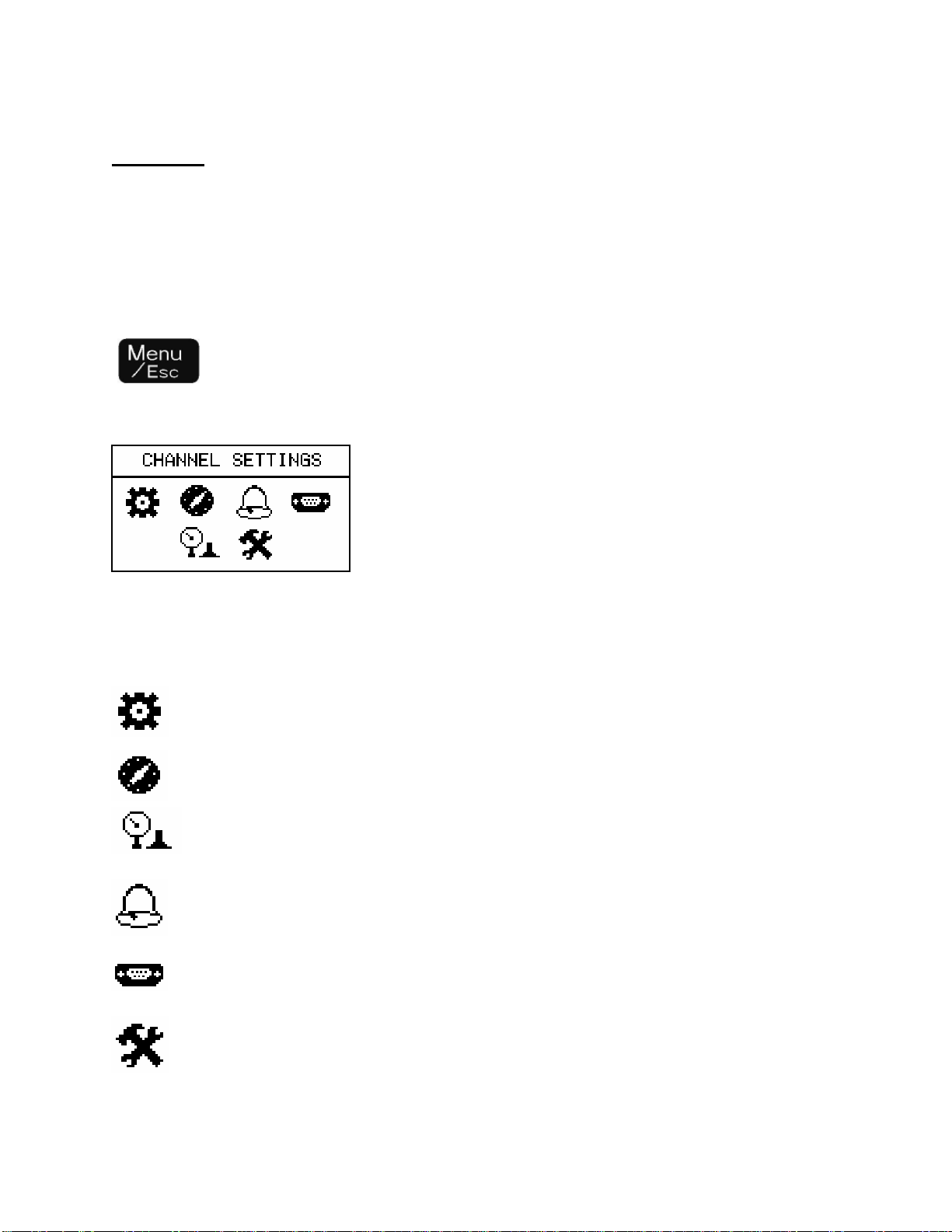
Pressing at any time during configuration will prompt you to save the
changes. Select “Yes” to save any changes made. Selecting “No” will not save
changes.
2) Configuration of each “Channel”
Using the arrows on the keypad, select the “Channel” icon.
Next, select the channel number to configure by pressing the up / down arrows and
pressing enter. The screens allow you to enable each channel and select the following:
Enable Channel Yes / No
Channel Type (0-1 V, 0-5 V, 0-10 V, 4-20 mA, J Type, K Type)
Description (name input with up to 20 characters)
Engineering Units (up to 3 characters for PSI, F, C etc…)
Enable alarms (read only or alarm?)
Alarm Type (latching or non-latching)
Alarm Output (select output #1, output #2 or both)
Alarm Low (select threshold for under-trip)
Alarm High (select threshold for over-trip)
Alarm Reset Points (select either the default reset value or manually set)
Alarm Reset Low (manually set reset hysteresis for low trip)

9
Alarm Reset High (manually set reset hysteresis for high trip)
3) Configuration of “Calibration”
Using the arrows on the keypad, select the “Calibration” icon.
Next, select the channel number to configure by pressing the up / down arrows and
pressing enter.
The screens allow you to define the “Cal Zero” and “Cal Span” values for any channels
that are configured for 0-1 V, 0-5 V, 0-10 V or 4-20 mA inputs.
Example 1:
A pressure transmitter is connected to channel # 1. The transmitter has a 4-20 mA
output representing a pressure input of 0 - 500 PSI. The “Cal Zero” and “Cal Span”
values would be defined as:
Cal Zero = 0
Cal Span = 500
Note that the “Engineering Units” would be input as PSI in “Channel” configuration
above.
Example 2:
An oxygen sensor is connected to channel # 4. The output of the oxygen sensor is
0-1 VDC (0-1000 mV). The “Cal Zero” and “Cal Span” values would be defined as:
Cal Zero = 0
Cal Span = 1000
Note that the “Engineering Units” would be input as mV in “Channel” configuration
above.
4) Alarm Logs
Selecting “Alarm Logs” will allow the following (2) options:
Show Active alarms:
- displays any active alarms & date / time information
Show All alarms
- allows display of each channel with historical date / time information

10
5) Communication
The unit provides access to the internal registered values using the Modbus Protocol.
The diagram below shows the recommended connections to the Phoenix connectors on
the back of the unit for either half-duplex or full-duplex (RS485).
Note: The termination resistor is not included above and the user needs to connect this
resistor as needed by the wiring configuration.
The Modbus address registers defined below are input register type (Function Code 04)
using two’s complement representation for the signed integers.
Address Description Data type
30000 Status Register : Bits 0 - 9 Alarms, Bit 15 Run Status Unsigned 16 bit integer
30001 - 30006 Absolute Values for Channels 1 – 6 Signed 16 bit integer
30007 - 30009 Differential Values for channels 1 & 2, 3 & 4, 5 & 6 Signed 16 bit integer
30010 - 30015 High Alarm Setting for Channels 1 - 6 Signed 16 bit integer
30016 - 30018 High Alarm Setting for Differentials 1 & 2, 3 & 4, 5 & 6 Signed 16 bit integer
30019 - 30024 Low Alarm Settings for Channels 1 - 6 Signed 16 bit integer
30025 - 30027 Low Alarm Settings for Differentials 1 & 2, 3 & 4, 5 & 6 Signed 16 bit integer
30028 RPM Unsigned 16 bit integer
30029 Hour meter Unsigned 16 bit integer

11
6) System
Using the arrows on the keypad, select the “System” icon.
There are (3) display layouts available. Selecting layout A, B or C will define the
preferred display type as follows:
Layout A: Displays groups of (2) input channels plus differential.
Layout B: Displays all inputs as bar graph plus each individual channel.
Layout C: Displays each individual channel in large format.
Note that you are selecting the default layout type. You will be able to change the layout
during normal operation by pressing the left / right arrows.
Operation
Once programmed, the UM-600 will begin scanning all enabled channel inputs and will
initiate alarms based on over / under threshold values configured for each channel. It is
not necessary to define alarm threshold values for all channels as some may be for
monitoring only.
Alarm Outputs
The UM-600 will alarm when channel values or differential values are above or below
limits as specified. Alarms can be configured as either latching or non-latching. If an
alarm condition is met, the red LED on the front panel will blink and the digital output(s)
will trip. The alarm point name (ch1, ch2, df1, df2) that caused the alarm will be stored
in memory with date/time stamp info. Non-latching alarms will reset the alarm if its value
returns to normal. Latching alarms require manual resetting via the front keypad.
Selecting the alarm icon will allow you to view any active alarms as well as the
history log for each channel. Once an active alarm is acknowledged, it will be placed
into the history log. The history log will continuously store the last 10 alarms for each
channel as well as the time & date of each alarm occurrence.

12
Other Dynalab Measuring Instrument manuals
Popular Measuring Instrument manuals by other brands

Beko
Beko FLM SF53 Installation and operation instruction

Graco
Graco EFC C Series Instructions-parts list

Anton Paar
Anton Paar SmartRef Instruction Manual and Safety Information

Spectrum Technologies
Spectrum Technologies WatchDog 3305ADD product manual

Hilti
Hilti PM 2-L operating instructions

Hanna Instruments
Hanna Instruments HI83303 instruction manual