Dynamic DYN-120 User manual

1
2” and 2” Tandem
Polarized-Media
Air Cleaners
Installation
&
Operation
Manual
All Dynamic Air Cleaners operate with the same basic principles of active-field polarized media. In the 2” Panel
Air Cleaner, the 24 VAC input to the Powerhead is stepped up to 7 kV (DC) at very low current. This voltage is
applied to the center screen inside the replaceable media pad. This creates an electrostatic field between the
center screen and the grounded exterior metal screens. The electrostatic field polarizes both the fibers in the
media and airborne contaminants. These are then attracted to and collected by the media fibers. When the
pads are loaded, they are easily removed and replaced.
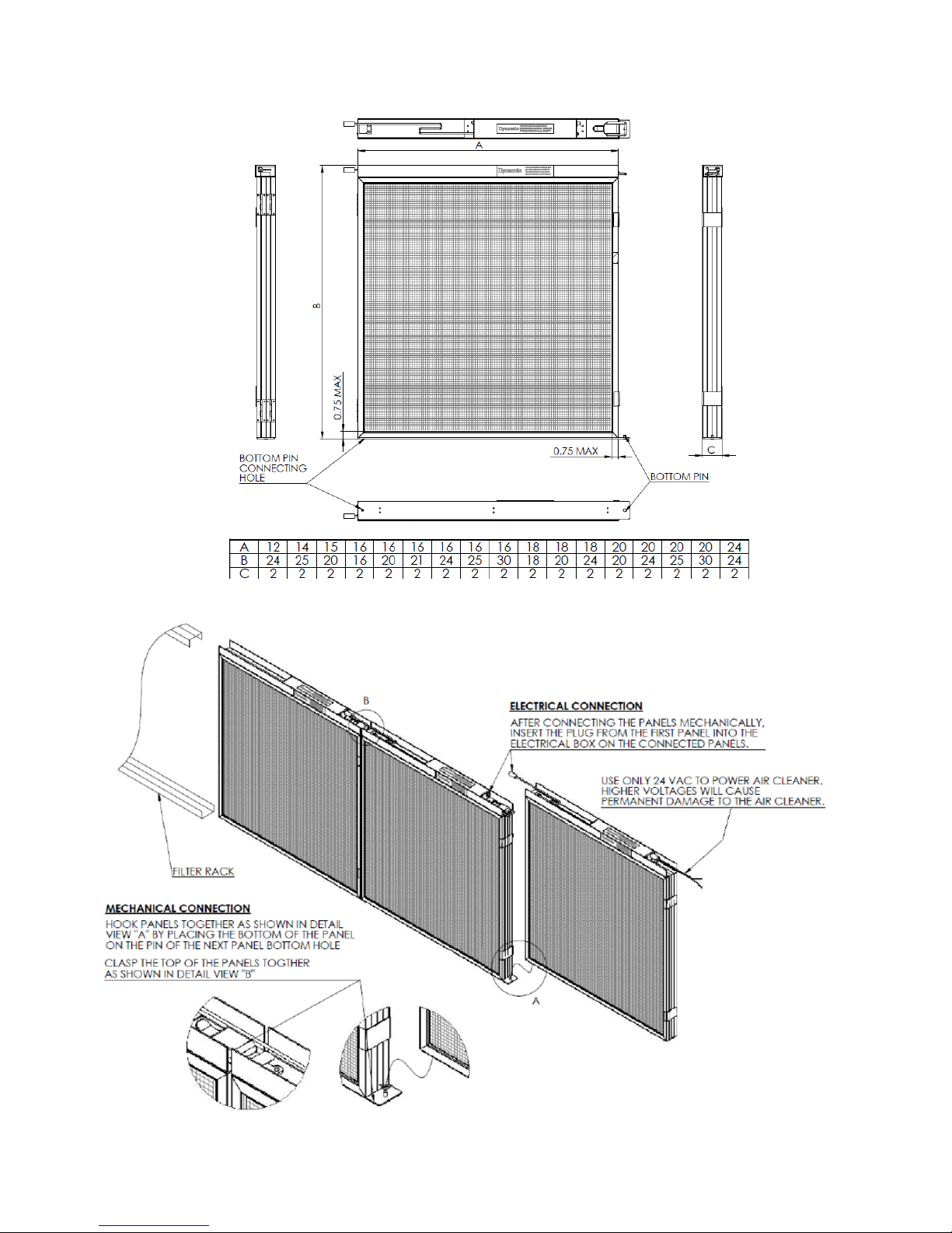
Dynamic 2” Air Cleaners typically slide into the standard 2” racks in the air handler. They are available as
individual Panels or as Tandem Panels. Typically, a Panel Air Cleaner is used when there is only one filter per
row. Each Panel is wired separately. Tandem Panels are used when there are multiple Air Cleaners per row.
They are connected mechanically and electrically to the adjacent Air Cleaner, and there is one electrical
connection per row. The entire row may be pulled out for service. Neoprene foam strips are used on the mating
faces of the Air Cleaners in a row to block the flow of air between Panels.
Section I. Sizing
While Air Cleaner height is consistent with filter rack height, Air Cleaner widths are typically sized to minimize the
number of Air Cleaners in a row and fill the width of the rack in the unit. Keeping the Air Cleaner width consistent
will also standardize replacement media pad size. For example, a rack that has three 24”x24”x2” passive filters
would typically take two 36”x24”x2” Dynamic Tandem Panels. Make sure that there is enough room to slide out
the larger Panel. In the above example, the Powerhead would go on top on the long side. When ordering, the
first dimension is the side with the Powerhead. Therefore, a 36”x24” Tandem is not the same as a 24”x36”
Tandem. Assuming a set of two, the first would give you an assembly that is 72” wide and 24” high and the
second would yield an assembly that is 48” wide and 36” high.
Like passive filters, 2” Panels are undersized from the nominal dimensions. They are undersized ½” on height
(the height of the filter track) and ¼” on width. Whenever possible, and on all retrofit applications, measure the
filter racks rather than relying on the nominal dimensions of the passive filters.
Section II. Installation
Dynamic 2” Panels slide into the existing filter racks. The required 24 VAC may come from an on-board source,
a dedicated transformer, or a Dynamic Control Panel, with optional pressure transmitter gauge. Make certain
that there is sufficient capacity (3 VA) when using an on-board transformer. Follow all applicable local codes.
Make certain the air handler is off when installing the Panels.
In the case of a Panel Air Cleaner, each Panel will require an electrical connection. With Tandem Panels, each
row requires its own input.

2
Figure 1
Figure 2
Black
Red

3
Note: Tandem Air Cleaners are wired in series and have a pre-wired pigtail to connect to the next panel
in the row. Each row of air cleaners is wired back to the power source. The electrical draw per panel is
3VA; a single transformer may be used to power all the air cleaners as long as the VA rating is greater
than the total power consumption of all the air cleaners. Wiring polarity must be maintained when
connecting the rows to the power source, i.e. all the red wires are connected together, all the black wires
are connected together.
Section III. Performance Data
Performance Data
Electrical Input:
24 VAC
Powerhead Output:
7.0 kV DC
Power Consumption per Panel:
2.8 Watts
Volt/Amps Draw per Panel:
3 VA
Ozone Generation:
None
Initial Static Pressure @ 300 fpm:
0.25”w.g.
Typical Final Static Pressure:
Initial SP X 2
Section IV. Maintenance
The only scheduled maintenance on any Dynamic Air Cleaner is the replacement of the media pads when they
are loaded. The replacement interval is usually determined by pressure drop. A general rule of thumb is to
change media when the pressure drop has doubled. Change-out frequency will, of course, depend on site
conditions and installation configuration. Dynamic replacement media pads should be expected to last longer
than passive filters.
In the event of build-up of larger particulate matter on the face of Air Cleaner screens, the screens may be
vacuumed or wiped off to extend media life. The Air Cleaners should never be sprayed with water or hosed down.
To order media pads, use the size on the sticker in the top channel. Do not measure a pad. Pad sizing is based
on the size of the overall Panel. To replace the media pads:
1) Because the media will have collected a great deal of contaminants, it is recommenced that maintenance
personnel wear gloves, a dust mask, and eye protection.
2) Turn off power to the Air Cleaners.
3) Pull out the first row of Air Cleaner Panels about 6” and unplug the power cord from the first Air Cleaner in the
row.
4) Pull the Air Cleaner Panels out of the rack. It is generally easier to un-latch and disconnect them from each
other as they are pulled out.
5) Remove and discard the dirty media pads. Brush or vacuum the Air Cleaner screens, if necessary.
6) Install the new media pads. The media pads are not directional. Make certain that the pads are properly
positioned. Please bear in mind, the replacement media pad for square Air Cleaner (e.g. 24x24) is not
square due to the Powerhead channel.
7) Re-connect Tandem Air Cleaner Panels mechanically and electrically and slide them back into their tracks.
When re-latching the Panels, the pin and hole at the bottom of adjacent Panels should be mated first, then
the latches engaged.
8) Re-connect the power cord to the first panel. Proceed to the next row.
9) When all the Air Cleaner Panels are re-connected, turn on power to the Air Cleaners. Visually inspect to
make sure that all indicator lights are illuminated. If the air handler door is equipped with a “kill switch” that
deactivates the Air Cleaner Panels, ensure that the door is closed prior to visually inspecting.
Section V. Media Pad Disposal
Used media pads generally may be thrown away with other standard trash. In some areas, they may be
recycled with glass bottles. This should be confirmed with your local recycler. As with passive filters, there may
be contaminants in specialized applications that prevent standard disposal or recycling and require special
handling. It is the responsibility of the operator to be aware of these and to act accordingly.

4
Section VI. Replacement Parts
1) Refer to the size label on the unit (item 12 in figure 3) for the unit size. Air Cleaner media pads are sized
according to the size of the overall Air Cleaner and NOT the size of the media pad itself.
2) When giving dimensions, always give the length of the Powerhead side first.
Item Description
1 Replacement Media Pad
2 Powerhead (inside channel)
3 Power Cord
4 Electrode Insulator Button
5 Air Cleaner Latch
6 Power ON Light
7 Label “Unplug before Opening”
8 Power Input Jack
9 Label
10 Electrode
11 Model / Power Rating Label
12 Air Cleaner Size Label
13 Patent Label
14 Hinge
15 Screen
16 Frame
17 Spline
Figure 3
FOR TECHNICAL SUPPORT CALL 1-800-578-7873
Dynamic Air Quality Solutions
P.O. Box 1258
Princeton, NJ 08542
Tel: (800) 578-7873
Fax (609) 924-8524
www.DynamicAQS.com
Specifications are subject to change without notice. Dynamic and Dynamic Air Quality Solutions are registered trademarks of
Environmental Dynamics Group, PO Box 1258, Princeton, NJ 08542
©2006 EDG DYN-120 (8/18)
Table of contents
Other Dynamic Air Cleaner manuals